1
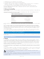
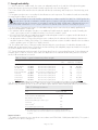
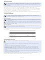
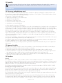
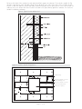
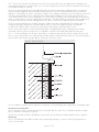
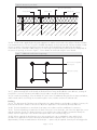
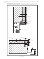
APPROVAL INSPECTION TESTING CERTIFICATION Wetherby Building Systems Limited 1 Kid Glove Road Golborne Enterprise Park Golborne Greater Manchester WA3 3GS Tel: 01942 717100 Fax: 01942 717101 TECHNICAL APPROVALS FOR CONSTRUCTION Agrément Certificate 14/5137 e-mail: [email protected] website: www.wbs-ltd.co.uk Product Sheet 1 WETHERBY EXTERNAL WALL INSULATION SYSTEMS EPSIBRICK 7 EXTERNAL WALL INSULATION SYSTEM This Agrément Certificate Product Sheet (1) relates to the Epsibrick 7 External Wall Insulation System, comprising enhanced expanded polystyrene (EPS) mechanicallyfixed with supplementary adhesive, reinforced basecoat and a clay brick-slip finish. It is suitable for use on new or existing domestic and non-domestic buildings. (1) Hereinafter referred to as ‘Certificate’. CERTIFICATION INCLUDES: • factors relating to compliance with Building Regulations where applicable • factors relating to additional non-regulatory information where applicable • independently verified technical specification • assessment criteria and technical investigations • design considerations • installation guidance • regular surveillance of production • formal three-yearly review. KEY FACTORS ASSESSED Thermal performance — the system can be used to improve the thermal performance of external walls and can contribute to meeting the requirements of the national Building Regulations (see section 6). Strength and stability — the system can adequately resist wind loads and impact damage (see section 7). Behaviour in relation to fire — the system has a Class 0 or ‘low risk’ reaction to fire classification as defined in the national Building Regulations (see section 8). Risk of condensation — the system can contribute to limiting the risk of interstitial and surface condensation (see section 11). Durability — when installed and maintained in accordance with the Certificate holder’s recommendations and the terms of this Certificate, the system should remain effective for at least 30-years (see section 13). The BBA has awarded this Certificate to the company named above for the system described herein. This system has been assessed by the BBA as being fit for its intended use provided it is installed, used and maintained as set out in this Certificate. On behalf of the British Board of Agrément Date of First issue: 8 July 2014 John Albon — Head of Approvals Claire Curtis-Thomas Originally certificated on Energy and Ventilation Chief Executive The BBA is a UKAS accredited certification body — Number 113. The schedule of the current scope of accreditation for product certification is available in pdf format via the UKAS link on the BBA website at www.bbacerts.co.uk Readers are advised to check the validity and latest issue number of this Agrément Certificate by either referring to the BBA website or contacting the BBA direct. British Board of Agrément Bucknalls Lane Watford Herts WD25 9BA ©2014 Page 1 of 18 tel: 01923 665300 fax: 01923 665301 e-mail: [email protected] website: www.bbacerts.co.uk Regulations In the opinion of the BBA, the Epsibrick 7 External Wall Insulation System, if installed, used and maintained in accordance with this Certificate, can satisfy or contribute to satisfying the relevant requirements of the following Building Regulations (the presence of a UK map indicates that the subject is related to the Building Regulations in the region or regions of the UK depicted): The Building Regulations 2010 (England and Wales) (as amended) Requirement: A1 Loading Comment: Requirement: B4(1) External fire spread The system can sustain and transmit wind loads to the substrate wall. See section 7.4 of this Certificate. Comment: The system can satisfy or contribute to satisfying this Requirement. See sections 8.1 to 8.4 of this Certificate. Requirement: C2(b) Resistance to moisture Comment: The system provides a degree of protection against rain ingress. See sections 4.4 and 10.1 of this Certificate. Requirement: C2(c) Resistance to moisture Comment: The system can contribute to minimising the risk of interstitial and surface condensation. See sections 11.1, 11.2 and 11.4 of this Certificate. Requirement: L1(a)(i) Conservation of fuel and power Comment: Regulation: 7 Materials and workmanship Comment: Regulation: Regulation: 26 26A CO2 emission rate for new buildings Fabric energy efficiency rates for new dwellings (applicable to England only) The system can contribute to satisfying this Requirement. See sections 6.2 and 6.3 of this Certificate. The system is acceptable. See section 13 and the Installation part of this Certificate. The system will enable, or contribute to enabling, a wall to satisfy the U value requirement. See sections 6.2 and 6.3 of this Certificate. Comment: The Building (Scotland) Regulations 2004 (as amended) Regulation: 8(1)(2) Durability, workmanship and fitness of materials The system can contribute to a construction satisfying this Regulation. See sections 12.1 and 13 and the Installation part of this Certificate. Comment: Regulation: Standard: 9 1.1 Building standards applicable to construction Structure Comment: Standard: 2.6 Spread to neighbouring buildings The system can sustain and transmit wind loads to the substrate wall. See section 7.4 of this Certificate. The system is regarded as ‘low risk’ and therefore can satisfy this Standard, with reference to clauses 2.6.4(1)(2), 2.6.5(1) and 2.6.6(2). See sections 8.1 to 8.6 of this Certificate. Comment: Standard: 2.7 Standard: 3.10 3.15 6.1(b) 6.2 7.1(a)(b) Comment Statement of sustainability The system can contribute to satisfying the relevant requirements of Regulation 9, Standards 1 to 6, and therefore will contribute to a construction meeting the bronze level of sustainability as defined in this Standard. In addition, the system can contribute to a construction meeting a higher level of sustainability as defined in this Standard with reference to clauses 7.1.4(1)(2) [Aspect 1(1)(2) and 2(1)], 7.1.6(1)(2) [Aspect 1(1)(2) and 2(1)] and 7.1.7(1)(2) [Aspect 1(1)(2)]. See sections 6.2 and 6.3 of this Certificate. Comment: Regulation: Carbon dioxide emissions Buildings insulation envelope The system can contribute to satisfying these Standards, with reference to clauses (or parts of) 6.1.1(1), 6.1.2(1)(2), 6.1.3(1)(2), 6.1.6(1), 6.1.10(2), 6.2.1(1)(2), 6.2.3(1), 6.2.4(2), 6.2.5(2), 6.2.6(1), 6.2.7(1), 6.2.8(2), 6.2.9(1)(2), 6.2.10(1), 6.2.11(1), 6.2.12(2) and 6.2.13(1)(2). See sections 6.2 and 6.3 of this Certificate. Comment: Standard: Condensation The system will satisfy the requirements of this Standard, with reference to clauses 3.15.1(1)(2), 3.15.4(1)(2) and 3.15.5(1)(2). See sections 11.3 and 11.4 of this Certificate. Comment: Standard: Standard: Precipitation The system will contribute to a construction satisfying this Standard, with reference to clauses 3.10.1(1)(2) and 3.10.2(1)(2). See sections 4.4 and 10.1 of this Certificate. Comment: Standard: Spread on external walls The system can satisfy the requirements of this Standard, with reference to clauses 2.7.1(1)(2) and 2.7.2(2). See sections 8.1 to 8.6 of this Certificate. Comment: 12 Building standards applicable to conversions All comments given for the system under Regulation 9, Standards 1 to 6, also apply to this Regulation, with reference to clause 0.12.1(1)(2) and Schedule 6(1)(2). (1) Technical Handbook (Domestic). (2) Technical Handbook (Non-Domestic). Page 2 of 18 The Building Regulations (Northern Ireland) 2012 Regulation: 23 Fitness of materials and workmanship Comment: Regulation: 28(b) Resistance to moisture and weather The system is acceptable. See section 13 and the Installation part of this Certificate. The system provides a degree of protection against rain ingress. See sections 4.4 and 10.1 of this Certificate. Comment: Regulation: 29 Condensation The system can contribute to minimising the risk of interstitial and surface condensation. See sections 11.2 and 11.4 of this Certificate. Comment: Regulation: 30 Stability Comment: Regulation: 36(a) External fire spread Comment: Regulation: Regulation: 39(a)(i) 40 Conservation measures Target carbon dioxide emission rate The system can sustain and transmit wind loads to the substrate wall. See section 7.4 of this Certificate. The system can satisfy or contribute to satisfying this Regulation. See sections 8.1 to 8.4 of this Certificate. Comment: The system can contribute to satisfying these Regulations. See sections 6.2 and 6.3 of this Certificate. Construction (Design and Management) Regulations 2007 Construction (Design and Management) Regulations (Northern Ireland) 2007 Information in this Certificate may assist the client, CDM co-ordinator, designer and contractors to address their obligations under these Regulations. See sections: 3 Delivery and site handling (3.2 and 3.4) of this Certificate. Additional Information NHBC Standards 2014 NHBC accepts the use of the Epsibrick 7 External Wall Insulation System, provided it is installed, used and maintained in accordance with this Certificate, in relation to NHBC Standards, Part 6 Superstructure (excluding roofs), Chapter 6.9 Curtain walling and cladding. Technical Specification 1 Description 1.1 The Epsibrick 7 External Wall Insulation System (see Figure 1) comprises, from inside to outside: Supplementary adhesive • Wetherby Bedding Adhesive — a cement-based, polymer-modified basecoat, comprising limestone sand conforming to BS EN 13139 : 2002, cement conforming to BS EN 197-1 : 2011 and additives. Supplied as a powder to which clean water is added. Insulation • Epsitherm 70E and 90E — enhanced expanded polystyrene (EPS) (grey) insulation boards measuring 1200 mm by 600 mm, in a range of thicknesses between 40 mm and 240 mm. The boards have a nominal density of 15 kg·m–3, a minimum compressive strength of 70 kPa (Epsitherm 70E) or 90 kPa (Epsitherm 90E) and a nominal tensile strength perpendicular to the face of 150 kPa. The boards are manufactured to comply with the requirements for EPS 70 or EPS 90, Class E material to BS EN 13163 : 2012. Mechanical fixings • mechanical fixings(1) — proprietary external wall insulation fixings of adequate length to suit the substrate and insulation thickness, selected from: — — — — — — — — — — Ejotherm NT U — Polyethylene (PE-HD) with stainless steel or galvanized steel pin Ejotherm NK U — Polyethylene (PE-HD) with stainless steel or galvanized steel pin Ejotherm NTK U — Polyethylene (PE-HD) with glassfibre reinforced polyamide pin SPIT ISO 10 — Polypropylene with glassfibre reinforced polyamide pin Koelner TFix-8M — Polypropylene with electro-galvanized steel pin Koelner TFix-8S/8ST — Polypropylene with electro-galvanized steel screw Termoz 8U — Polyamide with steel, stainless steel or galvanized screw Termoz 8UZ — Polypropylene with glassfibre reinforced polyamide screw Termoz CN 8 — Polypropylene with polyamide, steel, stainless steel or galvanized steel pin Bravoll PTH-S — Copolymer polypropylene with galvanized steel screw. (1) Other fixings may be used provided they can be demonstrated to have equal or higher pull-out, plate diameter and plate stiffness characteristics. Page 3 of 18 Basecoat • Wetherby Scrim Adhesive Basecoat — a cement-based, polymer-modified basecoat comprising limestone sand conforming to BS EN 13139 : 2002, cement conforming to BS EN 197-1 : 2011 and additives. Supplied as a powder to which clean water is added. Reinforcement • reinforcement mesh — a 1.0 m thick mesh (4 mm by 4 mm) of multi-strength alkali-resistant glassfibres, with a polymer coating and a nominal weight of 160 g·m–2. Brick-slip adhesive • Wetherby Brick-Slip Adhesive — high adhesive-strength cementitious-based mortar conforming to BS EN 12004 : 2007, cement conforming to BS EN 197-1 : 2011 and additives. Supplied as a grey powder to which clean water is added. Brick-slip finishes • Wetherby Brick-Slips — handmade, extruded or cut brick-slips, available in sizes 215 mm by 65 mm by 7 mm to 15 mm (average), conforming to BS EN 771-1 : 2011 and available in a range of colours • Wetherby Brick-Slip Pistols — 215/100 mm by 65 mm by 7 mm to 15 mm clay brick-slip pistol corners conforming to BS EN 14411 : 2012 and available in a range of colours. Pointing mortar • Wetherby Pointing Mortar— pre-coloured water-repellent, frost-resistant, cementitious pointing mortar, in accordance with BS EN 13888 : 2009 and conforming to BS EN 13139 : 2002. Supplied in powder form. 1.2 Ancillary materials also used with the system but outside the scope of this Certificate: • profiles — a range of standard profiles for wall base, end stop, corner mesh and expansion joints. Profiles are available in stainless steel, PVC-U or organic polyester powder-coated galvanized steel and are provided to the specifier’s requirements • profile fixings — hammer screws with plastic expansion • under- and over-sills, sill extenders • roof verge extenders • silicone sealant. Figure 1 Epsibrick 7 External Wall Insulation System supplementary adhesive reinforcement mesh brick-slip adhesive insulation board brick-slips basecoat 1.3 The insulation boards are mechanically fixed with supplementary adhesive (where required) to the external surface of the substrate. Five mechanical fixings are installed per board (7 per square metre), then basecoat render is trowel-applied to the board face to a thickness of 4 mm to 6 mm and the reinforcing mesh embedded immediately. One mechanical fixing per square metre is fixed through the mesh. The basecoat is lightly keyed and allowed to dry ready to accept the brick slips. The brick slip adhesive is applied to the back of each slip which is then installed onto the basecoat. Once the adhesive is dry pointing mortar is applied. 2 Manufacture 2.1 As part of the assessment and ongoing surveillance of product quality, the BBA has: • agreed with the manufacturer the quality control procedures and product testing to be undertaken • assessed and agreed the quality control operated over batches of incoming materials • monitored the production process and verified that it is in accordance with the documented process Page 4 of 18 • evaluated the process for management of nonconformities • checked that equipment has been properly tested and calibrated • undertaken to carry out the above measures on a regular basis through a surveillance process, to verify that the specifications and quality control operated by the manufacturer are being maintained. 2.2 The management system of Wetherby Building Systems Limited has been assessed and registered as meeting the requirements of BS EN ISO 9001 : 2008 and/or BS EN ISO 14001 : 2004 by Bureau Veritas (Certificate UK 9000006). 3 Delivery and site handling 3.1 The insulation is delivered to site shrink-wrapped in polythene packs bearing the manufacturer’s and product logo and batch numbers. 3.2 Components are delivered to site in the quantities and packages listed in Table 1. Each package carries the manufacturer’s and product logo and batch number. Table 1 Component supply details Component Quantity and packaging Basecoat Brick-slip adhesive Pointing mortar 25 kg bag Brick-Slips boxed by manufacturer Brick-Slip Pistols boxed by manufacturer Reinforcement mesh 1 m x 50 m rolls Mechanical fixings boxed by manufacturer 3.3 The insulation boards should be stored on a firm, clean, level base, off the ground and under cover until required for use. 3.4 The insulation boards must be protected from prolonged exposure to sunlight, either by storing opened packs under cover in dry conditions or re-covering with opaque polythene sheeting. Care must be taken when handling the insulation boards to avoid both damage and contact with solvents or materials containing volatile organic components. The boards must not be exposed to open flame and other ignition sources. Boards that become damaged, soiled or wet should be discarded. 3.5 The adhesive and basecoat components should be stored in dry conditions, off the ground, and protected from frost at all times. Bags of unopened render will have a shelf-life of 12 months when stored correctly. Assessment and Technical Investigations The following is a summary of the assessment and technical investigations carried out on the Epsibrick 7 External Wall Insulation System. Design Considerations 4 General 4.1 The Epsibrick 7 External Wall Insulation System, when installed in accordance with this Certificate, is effective in reducing the thermal transmittance (U value) of external masonry walls of new and existing buildings. For improved thermal/carbon-emissions performance, the designer should consider additional/alternative fabric and/or services measures. It is essential that the detailing techniques specified in this Certificate are carried out to a high standard if the ingress of water into the insulation is to be avoided, and the full thermal benefit obtained from the system. Only details specified by the Certificate holder should be used. 4.2 The system will improve the weather resistance of a wall and provide a decorative finish. However, it should only be installed where there are no signs of dampness on the inner surface of the wall, other than those caused solely by condensation. 4.3 The system is applied to the outside of external walls of masonry and dense or no-fines concrete construction and is suitable for use on new or existing domestic or non-domestic buildings up to 18 metres in height. Prior to installation of the system, the wall surfaces should comply with section 14 of this Certificate. 4.4 New buildings subject to national Building Regulations should be constructed in accordance with the relevant recommendations of: • BS EN 1996-2 : 2006 — the designer should select a construction appropriate to the local wind-driven rain index, paying due regard to the design detailing, workmanship and materials to be used • BS 8000-3 : 2001. Page 5 of 18 4.5 Other new buildings not subject to regulatory requirements, should also be built in accordance with the standards identified in section 4.4 of this Certificate. 4.6 The effect of the installation of the system on the acoustic performance of a construction is outside the scope of this Certificate. 4.7 The fixing of rainwater goods, satellite dishes, clothes lines, hanging baskets and similar items is outside the scope of this Certificate. 4.8 External plumbing should be removed before installation and alterations made to underground drainage, where appropriate, to accommodate repositioning of the plumbing on the finished face of the system. 4.9 It is essential that the system is installed and maintained in accordance with the conditions set out in this Certificate. 5 Practicability of installation The system should only be installed by specialised contractors who have successfully undergone training and registration by the Certificate holder. Note: The BBA operates a UKAS Accredited Approved Installer Scheme for external wall insulation; details of installer companies approved are included on the BBA’s website (www.bbacerts.co.uk). 6 Thermal performance 6.1 Calculations of thermal transmittance (U value) should be carried out in accordance with BS EN ISO 6946 : 2007, BS EN ISO 10211 : 2007 and BRE Report BR 443 : 2006, using the thermal conductivity (D value) of the insulation materials given in Table 2 of this Certificate. Table 2 Thermal conductivity of the insulation (D value) Thickness (mm) Insulation types Epsitherm EPS 70E Epsitherm EPS 90E 40 to 240 Thermal conductivity (W·m–1·K–1) 0.032 0.030 6.2 The U value of a completed wall will depend on the selected insulation type and thickness, fixing method, the insulating value of the substrate masonry and its internal finish. Calculated U values for sample construction in accordance with the Building Regulations are given in Table 3, and are based on the thermal conductivities given in Table 2. Table 3 Insulation thickness required to achieve design U values(1)(2) given in the national Building Regulations U value(4) (W·m–2·K–1) Thickness of insulation(3) (mm) 200 mm Dense blockwork, = 1.75 W·m–1·K–1 215 mm Brickwork, = 0.56 W·m–1·K–1 Epsitherm EPS 70E Epsitherm EPS 90E Epsitherm EPS 70E Epsitherm EPS 90E 0.18 190 180 200 190 0.19 180 170 190 170 0.25 130 120 140 130 0.26 120 110 130 120 0.28 110 100 120 110 0.30 100 100 110 100 0.35 80 80 90 90 (1) Wall construction inclusive of 13 mm plaster ( = 0.57 W·m–1·K–1), 15 mm Brick slip (render) ( = 0.77 W·m–1·K–1), brickwork (protected) with 17.1% mortar or dense blockwork with 6.7% mortar ( = 0.88 W·m–1·K–1). Thermal conductivity of insulation (D value) is as shown in Table 2. (2) Calculations based on a mechanical system that included 7 galvanized steel fixings per square metre with 8 mm diameter sleeve and with a point thermal transmittance (Xp= 0.004 W·K–1) per steel pin. Use of other types of fixings should be calculated in accordance with BS EN ISO 6946 : 2007. (3) Based upon incremental insulation thickness of 10 mm. (4) U values of 0.14 and 0.15 W·m–2·K–1 using Epsitherm EPS 90E and 0.15 and 0.16 W·m–2·K–1 using Epsitherm EPS 70E can be achieved with the maximum insulation thickness (240 mm). 6.3 The system can contribute to maintaining continuity of thermal insulation at junctions between elements and openings. For Accredited Construction Details, the corresponding -values (Psi) in BRE Information Paper IP 1/06, Table 3, may be used in carbon emission calculations in Scotland and Northern Ireland. Detailed guidance for other junctions and on limiting heat loss by air infiltration can be found in: England and Wales — Approved Documents to Part L and, for new thermal elements to existing buildings, Accredited Construction Details (version 1.0). For new-build, see also SAP 2009, Appendix K, and the iSBEM User Manual Scotland — Accredited Construction Details (Scotland) Northern Ireland — Accredited Construction Details (version 1.0). Page 6 of 18 7 Strength and stability 7.1 When installed on suitable walls, the system can adequately transfer to the wall the self-weight and negative (suction) and positive (pressure) wind loads normally experienced in the United Kingdom. 7.2 Positive wind load is transferred to the substrate wall directly via bearing and compression of the brick-slips, and insulation. 7.3 Negative wind pressure is resisted by the bond between each component. The insulation boards are retained by the external wall insulation system anchors. 7.4 The wind loads on the wall should be calculated in accordance with BS EN 1991-1-4 : 2005 and its UK National Annex. Special consideration should be given to locations with high wind-load pressure coefficients as additional fixings may be necessary. In accordance with BS EN 1990 : 2002 and its UK National Annex, it is recommended that a load factor of 1.5 is used to determine the ultimate wind load to be resisted by the system. 7.5 Assessment of structural performance for individual buildings must be carried out by a suitably qualified and experienced individual to confirm that: • the substrate wall has adequate strength to resist additional loads that may be applied as a result of installing the system, ignoring any positive contribution that may occur from the insulation system • the proposed system and associated fixing layout provides adequate resistance to negative wind loads based on the results of the site investigation and test results • an appropriate number of site-specific pull-out tests are conducted on the substrate of the building to determine the minimum resistance to failure of the fixings. The characteristic pull-out resistance should be determined in accordance with the guidance given in ETAG 014 : 2002, Annex D. 7.6 The number and centres of fixings should be determined by the system designer. Provided the substrate wall is suitable and an appropriate fixing is selected, the mechanical fixings will adequately support and transfer the weight of the render insulation system to the substrate wall. 7.7 Typical characteristic pull-out strengths for the fixings taken from the corresponding European Technical Approval (ETA) are given in Table 4; however, these values are dependent on the substrate and the fixing must be selected to suit the loads and substrate concerned. Table 4 Fixings — typical characteristic pull-out strengths Fixing type ETA number Substrate Drill diameter (mm) Embedment Typical pull-out depth (mm) strength (kN) Ejotherm NT U/NK U Ejotherm NTK U SPIT ISO 10 Koelner TFix-8M Koelner TFix-8S/8ST Termoz 8U 05/0009 07/0026 04/0076 07/0336 11/0144 02/0019 Concrete C12/15/Clay bricks Concrete C12/15/Clay bricks Concrete C12/15/Clay bricks Concrete C12/15/Clay bricks Concrete C12/15/Clay bricks (solid) Concrete C12/15/Clay bricks 8 8 10 8 8 8 25 40 30 25 25 70 1.2/1.5 0.6/0.9 0.60/0.75 1.2/1.2 1.2/1.2 1.5/1.5 Termoz 8UZ 02/0019 Concrete C12/15/Clay bricks 8 30 1.2/1.5 Termoz CN 8 09/0394 Concrete C12/15/Clay bricks 8 35 0.9/0.9 Bravoll PTH-S 08/0267 Concrete C12/15/Clay bricks 8 25 1.5/1.5 7.8 The resistance forces data given in Table 5 are the results of calculations based upon pull-through resistances determined by the BBA from tests on anchors with 60 mm plate diameter and minimum plate stiffness of 0.4 kN·mm–1. Table 5 Pull-through resistances Factor (unit) Insulation Epsitherm EPS 70E Thickness (mm) 90 Tensile resistance of insulation (kPa) Plate diameter of anchor (mm) 150 60 Characteristic pull-through resistance(1) (per anchor) (N) 323 Factor of safety(2) 2.5 Design pull-through resistance (N) 129 (1) Characteristic value in accordance with BS EN 1990 : 2002, Annex D7.2. (2) The safety factor of 2.5 is applied and based on the assumption that all insulation boards are quality control tested to establish tensile strength perpendicular to the face of the board. Impact resistance 7.9 Hard body impact tests were carried out in accordance with ETAG 004 : 2000 (amended 2013). The system is suitable for use in all Use Categories(1). Page 7 of 18 (1) The Use Categories are defined in ETAG 004 : 2000 (amended 2013) as: • Category I — a zone readily accessible at ground level to the public and vulnerable to hard body impacts but not subjected to abnormally rough use • Category II — a zone liable to impacts from thrown or kicked objects, but in public locations where the height of the system will limit the size of the impact; or at lower levels where access to the building is primarily to those with some incentive to exercise care • Category III – a zone not likely to be damaged by normal impacts caused by people or by thrown or kicked objects. 8 Behaviour in relation to fire 8.1 The external surfaces of the system are classified as Class 0 or ‘low risk’ as defined in the national Building Regulations. 8.2 The classification applies to the full range of thicknesses covered by this Certificate. 8.3 The system is restricted for use in buildings up to 18 metres in height. 8.4 For houses in Scotland and for all buildings in England and Wales and Northern Ireland, the system is suitable for use on, or at any distance from, the boundary. 8.5 For flats and maisonettes and non-domestic buildings in Scotland, the system is suitable only for use more than one metre from the boundary. 8.6 The system is not classified as ‘non-combustible’, therefore calculations for unprotected areas may apply, dependent on the fire resistance characteristics of the wall. 8.7 For application to second storey floors and above, it is recommended that the designer considers at least one stainless steel fixing per square metre and fire barriers in line with compartment walls and floors as advised in BRE Report BR 135 : 2013 (see Figure 2). Figure 2 Fire barrier brick-slips pointing mortar insulation board existing substrate 200 mm mineral fibre fire barrier fire-break stainless steel fixing mechanical fixing 9 Proximity of flues and appliances When the system is installed in close proximity to certain flue pipes, the relevant provisions of the national Building Regulations should be met: England and Wales — Approved Document J Scotland — Mandatory Standard 3.19, clause 3.19.4(1)(2) (1) Technical Handbook (Domestic). (2) Technical Handbook (Non-Domestic). Northern Ireland — Technical Booklet L. Page 8 of 18 10 Water resistance 10.1 The system will provide a degree of protection against rain ingress. However, care should be taken to ensure that substrate walls are adequately weathertight prior to its application. The insulation system shall only be installed where there are no signs of dampness on the inner surface of the substrate other than those caused solely by condensation. 10.2 Designers and installers should take particular care in detailing around openings, penetrations and movement joints to minimise the risk of rain ingress. Only details approved by the Certificate holder should be used. 10.3 The guidance given in BRE Report BR 262 : 2002 should be followed in connection with the weathertightness of solid wall constructions. The designer should select a construction appropriate to the local wind-driven rain index, paying due regard to the design detailing, workmanship and materials to be used. 10.4 At the tops of walls, the system should be protected by an adequate overhang or other detail designed for use with this type of system. 11 Risk of condensation 11.1 Designers must ensure that an appropriate condensation risk analysis has been carried out for all parts of a construction, including at junctions, openings and penetrations to minimise the risk of condensation. The recommendation of BS 5250 : 2011 should be followed. Surface condensation 11.2 Walls will adequately limit the risk of surface condensation when the thermal transmittance (U value) does not exceed 0.7 W·m–2·K–1 at any point and the junctions with other elements and openings comply with section 6.3 of this Certificate. 11.3 Walls will adequately limit the risk of surface condensation when the thermal transmittance (U value) does not exceed 1.2 W·m–2·K–1 at any point. Guidance may be obtained from BS 5250 : 2011 (Section 8, Annex D) and BRE Report BR 262 : 2002. Interstitial condensation 11.4 Walls incorporating the system will adequately limit the risk of interstitial condensation when they are designed and constructed in accordance with this Certificate. 11.5 The Equivalent air layer thickness (Sd) and water vapour resistance (µ) factor for the insulation boards and brickslips is as follows: Table 6 Equivalent air layer thickness (Sd) and water vapour resistance factor (µ) Description Sd (m) (µ) Enhanced EPS insulation boards (Epsitherm 70E and 90E) — 60(1) Clay Brick-Slip system 0.65(2) — (1) The water vapour resistance factor (µ) is taken from BS EN ISO 10456 : 2007, Table 4. (2) The values are obtained from tests, including those on the basecoat, mesh, brick-slip adhesive, brick-slips and pointing mortar. 12 Maintenance and repair 12.1 Regular checks should be made on the installed system, including: • visual inspection of the brick-slips for signs of disbandment. Dislodged slips should be re-fixed using brick-slip adhesive. • examination of the sealant around openings and service entry points • visual inspection of architectural details designed to shed water to confirm that they are performing properly • visual inspection to ensure that water is not leaking from external downpipes or gutters; such leakage could penetrate the rendering • necessary repairs effected immediately and the sealant joints at window and door frames replaced at regular intervals • maintenance schedules, which should include the replacement and resealing of joints, for example between the insulation system and window and door frames. 12.2 Damaged areas must be repaired using the appropriate components and the procedures detailed in the Certificate holder’s installation instructions and in accordance with BS EN 13914 : 2005. Page 9 of 18 13 Durability The system will remain effective for at least 30-years, provided any damage to the surface finish is repaired immediately and regular maintenance is undertaken, as described in section 12 of this Certificate. Installation 14 Site survey and preliminary work 14.1 A pre-installation survey of the property must be carried out to determine suitability for treatment and the need for any necessary repairs to the building structure before application of the Epsibrick 7 External Wall Insulation System. A specification is prepared for the building indicating: • the position of starter tracks and beads • detailing around windows, doors and at eaves • damp-proof course (dpc) level • exact position of expansion joints • areas where flexible sealants must be used • any alterations to external plumbing • where required, the position of fire barriers. 14.2 The survey should include tests conducted on the walls of the building by the Certificate holder or their approved installers (see section 15) to determine the pull-out resistance of the proposed mechanical fixings. An assessment and recommendation is made on the type and number of fixings required to withstand the building’s expected wind loading based on calculations using the relevant wind speed data for the site and the pull-out resistances (see section 7). 14.3 Surfaces should be sound, clean and free from loose material. The flatness of surfaces must be checked; this may be achieved using a straight-edge spanning the storey height. Any excessive irregularities, ie greater than 10 mm in 1 metre, must be made good prior to installation to ensure that the insulation boards are installed with a smooth, in-plane finished surface. 14.4 On existing buildings, purpose-made window sills must be fitted to extend beyond the finished face of the system (see Figure 5). New buildings should incorporate suitably deep sills. 14.5 Where surfaces are covered with an existing rendering, it is essential that the bond between the substrate and the render is adequate. All loose areas should be hacked off and reinstated. 14.6 Internal wet work, eg screeding or plastering, should be completed and allowed to dry prior to the application of the system. 15 Approved installers Application of the system, within the context of this Certificate, is carried out by approved installers recommended or recognised by the Certificate holder. Such an installer is a company: • employing operatives who have been trained and approved by the Certificate holder to install the system • which has undertaken to comply with the Certificate holder’s application procedure, containing the requirement for each application team to include at least one member operative trained by the Certificate holder • subject to at least one inspection per annum by the Certificate holder to ensure suitable site practices are be employed. This may include unannounced site inspections. 16 Procedure General 16.1 Application is carried out in accordance with the current installation instructions of the Certificate holder. 16.2 Weather conditions should be monitored to ensure correct application and curing conditions. The basecoat and adhesive materials should not be applied at temperatures below 5°C or above 30°C, if exposure to frost is likely or in damp/wet conditions. The render must be protected from rapid drying. 16.3 Basecoat rendering should be in accordance with the relevant recommendations of BS EN 13914-1 : 2005. Positioning and securing insulation boards 16.4 The base profile is secured to the external wall, line and level, above the dpc using the approved profile fixings at 300 mm centres maximum. Base profile connectors are inserted at all rail joints. Extension profiles are fixed to the front lip of the base profile or stop end channel where appropriate (see Figure 3). 16.5 Stop beads are positioned vertically or by using the ‘wrap back’ technique, eg at party wall positions where the adjoining house does not require treatment. 16.6 The Wetherby Bedding Adhesive is prepared by mixing each 25 kg bag with 4.5 to 5 litres of clean water. The supplementary adhesive must be applied to the back of the insulation board by one of two methods, depending on whether the substrate is flat or undulating. Firstly, the adhesive can be applied with a 10 mm notch trowel to the Page 10 of 18 full area of the back of the insulation board, and placed firmly against the substrate. This method is suitable for flat substrates. Alternatively, a dot and dab method can be adopted. In this method, the edges of the insulation board must be coated with adhesive, and 3 large dabs of adhesive applied at even spacing to the centre of the board. The adhesive must cover at least 40% of the board. The board is then placed firmly against the substrate. This method is suitable for undulating substrates. Figure 3 Typical section at base level Figure 4 Insulation boards fixing patterns insulation fixings 300 mm max 300 mm max fixings at a maximum of 300 mm centres around all openings window/door opening 50 mm 50 mm fixings at a maximum of 300 mm centres at building corner 50 mm 50 mm 300 mm max Page 11 of 18 16.7 The first run of insulation boards are positioned on the base profile. Holes are drilled into the substrate to the required depth through the insulation at the corners of each and at positions which will allow a minimum of five fixings per insulation board (see Figure 4). 16.8 The insulation boards are mechanically fastened to the wall using the approved fixing pattern (see Figure 4). Around openings, additional fixings should be used at 300 mm centres. The mechanical fixings are inserted and tapped or screwed firmly into place, securing the insulation to the substrate. Subsequent rows of boards are positioned so that the vertical board joints are staggered and overlapped at the building corners and the board joints do not occur within 200 mm of the corners of openings. At corners, fixings should be positioned inwards by 75 mm, plus the thickness of the insulation. Holes are drilled into the substrate to a minimum depth specified by the fixing supplier and the mechanical fixings are inserted and tapped firmly into place, securing the insulation board to the substrate. 16.9 Five mechanical fixings per board (7 fixings per square metre) are installed through the insulation and one mechanical fixing per square metre is fixed through the mesh to secure the insulation boards to the substrate. A 100 mm by 100 mm patch is placed over each fixing head of fixings installed through the mesh. 16.10 Care must be taken to ensure that all board edges are butted tightly together, and alignment should be checked as work proceeds. Any high spots or irregularities should be removed by lightly planing with a rasp. 16.11 To fit around details such as doors and windows, insulation boards may be cut with a sharp knife, fine-tooth saw or hot-wire cutting machine. If required, purpose-made window sills are fitted (see Figure 5). They are designed to prevent water ingress and incorporate drips to shed water clear of the system. Figure 5 Typical sill detail 16.12 Installation continues until the substrate is completely covered including, where appropriate, the building soffits. Movement joints and profiles 16.13 Movement joints in the substrate must be continued through the system. The joint detail using purpose-made PVC or metal trims is illustrated in Figure 6. 16.14 Corner beads are fixed to all building corners and to door and window heads and jambs where required. Reinforcing 16.15 The Wetherby Scrim Adhesive Basecoat is prepared by mixing the contents of each 25 kg bag with 4 to 5 litres of clean water. Page 12 of 18 Figure 6 Movement joint detail approved mechanical fixing PVC movement joint with firtree fixings existing substrate insulation board pointing mortar brick-slips 16.16 The basecoat is applied either by spray equipment or stainless steel trowel to the surface of the dry insulation to a minimum thickness of 4 mm. The mesh is bedded immediately into the basecoat with 100 mm minimum overlap at joints; it must be in the upper third of the basecoat render. Mechanical fixings are applied as described in section 16.9 of this Certificate. Additional pieces of reinforcing mesh (200 mm by 200 mm) are used diagonally at the corners of openings, as shown in Figure 7. Corner details are reinforced using the corner beads. Figure 7 Additional reinforcement at openings 200 mm x 200 mm glassfibre reinforcing mesh window/door opening 16.17 Surface-mounted PVC render beads are fixed with fir-tree fixings and bedded in scrim adhesive, ensuring all mesh/PVC is covered. The basecoat should be keyed, ready to accept the brick-slip finish. 16.18 In multi-storey buildings, holes are drilled at 1 metre centres for additional fixings before the basecoat hardens, and fire rated stainless steel fixings are inserted through the scrim, insulation and into the substrate wall. Finishing 16.19 The drying period of the basecoat will depend on the applied thickness and weather conditions; however, the basecoat must be left to harden for at least one day before application of the Wetherby Brick-Slip Adhesive. 16.20 The brick-slip adhesive is mixed with clean water in accordance with the manufacturer’s instructions. 16.21 The brick-slip adhesive is buttered to the back of the pistol corners brick-slips, which are then applied to corners and door/window reveals. The distance between corners and/or outer edges should be measured to identify the number of bricks required per course and the subsequent width of the vertical pointing joint. 16.22 Where required, the brick-slips are cut to size using a bench saw or standard tile cutter and the brickslip adhesive is applied to the back of brick-slips and installed at the required location. Consistent joint spaces (approximately 10 mm) are made between the brick-slips — spacers may be required. Vertical joints are staggered to Page 13 of 18 give the appearance of conventional brickwork or installed in a stack bond pattern in accordance with the required design. Figure 8 Insulated window or door reveal pointing mortar brick-slips insulation board existing substrate mechanical fixing mechanical fixing insulation board corner bead silicone sealant conjectured line of existing window mechanical fixing existing substrate insulation board brick-slips pointing mortar brick-slip corner pistol corner bead insulation board mechanical fixing silicone sealant Page 14 of 18 Figure 9 Typical eaves detail 16.23 After brick-slip application, sealant is positioned and installed at all openings (eg windows and doors), overhanging eaves, gas and electric meter boxes, wall vents or where the brick-slips abut any other building material or surface. This helps to reduce the risk of water ingress into the structure. 16.24 Care should be taken in the detailing of the system around features such as openings, projections and at eaves (see Figure 8) to ensure adequate protection against water ingress and to limit the risk of water penetrating the system. 16.25 Once the brick-slips have set, pointing is performed using Wetherby Pointing Mortar and a pointing gun. Shaping of the mortar is done by using a pointing trowel. Once the mortar is dry, walls should be brushed to remove all loose mortar etc. 16.26 At the tops of walls, the system must be protected by an adequate overhang or by an adequately-sealed purpose-made flashing (see Figure 9). 16.27 On completion, external fittings are re-fixed to the substrate using suitable fixing pads previously installed in the system, or a retrospective solution approved by the Certificate holder. Page 15 of 18 Technical Investigations 17 Tests Tests were carried out on Epsibrick 7 External Wall Insulation System to determine: • resistance to freeze/thaw • heat/spray cycling • impact resistance • water vapour permeability • fire performance • thermal conductivity to BS EN ISO 6946 : 2007 • bond strength • durability of finish coatings • pull-through resistance. 18 Investigations 18.1 The manufacturing process was evaluated, including the methods adopted for quality control, and details were obtained of the quality and composition of materials used. 18.2 An assessment of the risk of interstitial condensation was undertaken. 18.3 The practicability of installation and the effectiveness of detailing techniques were examined. Page 16 of 18 Bibliography BS 5250 : 2011 Code of practice for control of condensation in buildings BS 8000-3 : 2001 Workmanship on building sites — Code of practice for masonry BS EN 197-1 : 2011 Cement — Composition, specifications and conformity criteria for common cements BS EN 771-1 : 2011 Specification for masonry units — Clay masonry units BS EN 1990 : 2002 Eurocode — Basis of structural design NA to BS EN 1990 : 2002 UK National Annex to Eurocode — Basis of structural design BS EN 1991-1-4 : 2005 Eurocode 1 — Actions on structures — General actions — Wind actions NA to BS EN 1991-1-4 : 2005 UK National Annex to Eurocode 1 — Actions on structures — General actions — Wind actions BS EN 1996-2 : 2006 Eurocode 6 — Design of masonry structures — Design considerations, selection of materials and execution of masonry BS EN 12004 : 2007 Adhesives for tiles — Requirements, evaluation of conformity, classification and designation BS EN 13139 : 2002 Aggregates for mortar BS EN 13163 : 2012 Thermal insulation products for buildings — Factory made expanded polystyrene (EPS) products — Specification BS EN 13888 : 2009 Grout for tiles — Requirements, evaluation of conformity, classification and designation BS EN 13914-1 : 2005 Design, preparation and application of external rendering and internal plastering — External rendering BS EN 14411 : 2012 Ceramic tiles — Definitions, classification, characteristics, evaluation of conformity and marking BS EN ISO 6946 : 2007 Building components and building elements — Thermal resistance and thermal transmittance — Calculation method BS EN ISO 9001 : 2008 Quality management systems — Requirements BS EN ISO 10211 : 2007 Thermal bridges in building construction — Heat flows and surface temperatures — Detailed calculations BS EN ISO 10456 : 2007 Building materials and products — Hygrothermal properties — Tabulated design values and procedures for determining declared and design thermal values BS EN ISO 14001 : 2004 Environmental management systems — Requirements with guidance for use BRE Report (BR 135 : 2013) Fire performance of external insulation of walls of multistorey buildings BRE Report (BR 262 : 2002) Thermal insulation: avoiding risks BRE Report (BR 443 : 2006) Conventions for U-value calculations ETAG 004 : 2000 Guideline for European Technical Approval of External Thermal Insulation Composite Systems with Rendering ETAG 004 : 2013 Guideline for European Technical Approval of External Thermal Insulation Composite Systems with Rendering ETAG 014 : 2002 Guideline for European Technical Approval of Plastic Anchors for fixing of External Thermal Insulation Composite Systems with Rendering Page 17 of 18 Conditions of Certification 19 Conditions 19.1 This Certificate: • relates only to the product/system that is named and described on the front page • is issued only to the company, firm, organisation or person named on the front page — no other company, firm, organisation or person may hold or claim that this Certificate has been issued to them • is valid only within the UK • has to be read, considered and used as a whole document — it may be misleading and will be incomplete to be selective • is copyright of the BBA • is subject to English Law. 19.2 Publications, documents, specifications, legislation, regulations, standards and the like referenced in this Certificate are those that were current and/or deemed relevant by the BBA at the date of issue or reissue of this Certificate. 19.3 This Certificate will remain valid for an unlimited period provided that the product/system and its manufacture and/or fabrication, including all related and relevant parts and processes thereof: • are maintained at or above the levels which have been assessed and found to be satisfactory by the BBA • continue to be checked as and when deemed appropriate by the BBA under arrangements that it will determine • are reviewed by the BBA as and when it considers appropriate. 19.4 The BBA has used due skill, care and diligence in preparing this Certificate, but no warranty is provided. 19.5 In issuing this Certificate, the BBA is not responsible and is excluded from any liability to any company, firm, organisation or person, for any matters arising directly or indirectly from: • the presence or absence of any patent, intellectual property or similar rights subsisting in the product/system or any other product/system • the right of the Certificate holder to manufacture, supply, install, maintain or market the product/system • actual installations of the product/system, including their nature, design, methods, performance, workmanship and maintenance • any works and constructions in which the product/system is installed, including their nature, design, methods, performance, workmanship and maintenance • any loss or damage, including personal injury, howsoever caused by the product/system, including its manufacture, supply, installation, use, maintenance and removal • any claims by the manufacturer relating to CE marking. 19.6 Any information relating to the manufacture, supply, installation, use, maintenance and removal of this product/ system which is contained or referred to in this Certificate is the minimum required to be met when the product/system is manufactured, supplied, installed, used, maintained and removed. It does not purport in any way to restate the requirements of the Health and Safety at Work etc. Act 1974, or of any other statutory, common law or other duty which may exist at the date of issue or reissue of this Certificate; nor is conformity with such information to be taken as satisfying the requirements of the 1974 Act or of any statutory, common law or other duty of care. British Board of Agrément Bucknalls Lane Watford Herts WD25 9BA ©2014 Page 18 of 18 tel: 01923 665300 fax: 01923 665301 e-mail: [email protected] website: www.bbacerts.co.uk