1
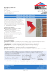
APPROVAL INSPECTION TESTING CERTIFICATION Sto Ltd 2 Gordon Avenue Hillington Park Glasgow G52 4TG Tel: 0141 892 8000 Fax: 0141 404 9001 TECHNICAL APPROVALS FOR CONSTRUCTION Agrément Certificate 13/4970 e-mail: [email protected] website: www.sto.co.uk Product Sheet 1 STOMIX EXTERNAL WALL INSULATION SYSTEMS STXTHERM ECO EXTERNAL THERMAL INSULATION SYSTEM PRODUCT SCOPE AND SUMMARY OF CERTIFICATE This Certificate relates to the StxTherm Eco External Thermal Insulation System, for use as an external insulation and decorative finish on exterior walls of new or existing buildings constructed of masonry or concrete. AGRÉMENT CERTIFICATION INCLUDES: • factors relating to compliance with Building Regulations where applicable • factors relating to additional non-regulatory information where applicable • independently verified technical specification • assessment criteria and technical investigations • design considerations • installation guidance • regular surveillance of production • formal three-yearly review. KEY FACTORS ASSESSED Practicability of installation — the system should only be installed by installers who have been trained and approved by the Certificate holder (see section 4). Strength and stability — a correctly designed system will have adequate resistance to wind loads and, in certain applications, impact damage (see section 5). Behaviour in relation to fire — the system incorporates materials which would not be classed as ‘non-combustible’ but can meet national fire regulations subject to certain restrictions (see sections 6 and 7). Thermal performance — the system can be used to improve the thermal performance of external walls and contributes to meeting the requirements of the building regulations (see section 10). The BBA has awarded this Agrément Certificate to the company named above for the system described herein. This system has been assessed by the BBA as being fit for its intended use provided it is installed, used and maintained as set out in this Certificate. On behalf of the British Board of Agrément Date of First issue: 27 February 2013 Sean Moriarty — Head of Approvals Greg Cooper Energy and Ventilation Chief Executive Certificate amended on 25 June 2014 to add Sto Turbofix adhesive as a component. The BBA is a UKAS accredited certification body — Number 113. The schedule of the current scope of accreditation for product certification is available in pdf format via the UKAS link on the BBA website at www.bbacerts.co.uk Readers are advised to check the validity and latest issue number of this Agrément Certificate by either referring to the BBA website or contacting the BBA direct. British Board of Agrément Bucknalls Lane Watford Herts WD25 9BA ©2013 Page 1 of 16 tel: 01923 665300 fax: 01923 665301 e-mail: [email protected] website: www.bbacerts.co.uk Regulations In the opinion of the BBA, StxTherm Eco External Thermal Insulation System, if used in accordance with the provisions of this Certificate, will meet or contribute to meeting the relevant requirements of the following Building Regulations: The Building Regulations 2010 (England and Wales) Requirement: A1 Loading Comment: Requirement: B4(1) External fire spread Comment: Requirement: C2(b) Resistance to moisture Comment: Requirement: C2(c) Resistance to moisture The system can sustain and transmit loads to the substrate wall. See section 5.4 of this Certificate. The system can meet this Requirement. See sections 6.1 to 6.4, 6.7 and 7 of this Certificate. The system provides a degree of protection against rain ingress. See sections 8.1 to 8.4 of this Certificate. Comment: The system contributes to minimising the risk of interstitial and surface condensation. See sections 9.3 to 9.7 of this Certificate. Requirement: L1(a)(i) Conservation of fuel and power Comment: The system can contribute to enabling a wall to meet the Target Emission Rate. See section 10.3 of this Certificate. Requirement: Regulation 7 Materials and workmanship Comment: The system is acceptable. See section 12.1 and the Installation part of this Certificate. The Building (Scotland) Regulations 2004 (as amended) Regulation: 8(1)(2) Fitness and durability of materials and workmanship The use of the system satisfies the requirements of this Regulation. See sections 11.1 and 12.1 and the Installation part of this Certificate. Comment: Regulation: Standard: 9 1.1 Building standards — construction Structure Comment: Standard: 2.6 Spread to neighbouring buildings The system can sustain and transmit wind loads to the substrate wall. See section 5.4 of this Certificate. The system incorporates materials which would not be classed as ‘non-combustible’. Completed walls, therefore, would be regarded as unprotected areas as defined in this Standard, with reference to clauses 2.6.1(1)(2) and 2.6.2(1)(2). See sections 6.1 to 6.4, 6.7 and 7 of this Certificate. Comment: Standard: 2.7 Standard: 3.10 3.15 Condensation Walls insulated with the system will satisfy the requirements of clauses 3.15.1(1), 3.15.4(1) and 3.15.5(1) of this Standard. See sections 9.3 to 9.7 of this Certificate. Comment: Standard: Standard: Precipitation Walls insulated with the system will contribute to a construction satisfying this Standard, with reference to clause 3.10.1(1)(2). See sections 8.1 to 8.4 of this Certificate. Comment: Standard: Spread on external walls The system incorporates materials which would not be classed as ‘non-combustible’ as defined in clauses 2.7.1(1)(2) and 2.7.2(2) of this Standard, and should not therefore be used on walls one metre or less from a boundary. See sections 6.1 to 6.4, 6.7 and 7 of this Certificate. Comment: 6.1(b) 6.2 Carbon dioxide emissions Buildings insulation envelope The system can contribute to satisfying this Standard, with reference to all or part of clauses 6.1.1(1), 6.1.2(1), 6.1.3(2), 6.1.6(1), 6.2.1(1)(2), 6.2.3(1)(2), 6.2.4(1), 6.2.5(1)(2), 6.2.8(2) and 6.2.10(2). See section 10.3 of this Certificate. Comment: (1) Technical Handbook (Domestic). (2) Technical Handbook (Non-Domestic). The Building Regulations (Northern Ireland) 2012 Regulation: 23 Fitness of materials and workmanship Comment: Regulation: 28 Resistance to ground moisture and weather Comment: Regulation: 29 Condensation The system is acceptable. See section 12.1 and the Installation part of this Certificate. Walls insulated with the system will satisfy this Regulation. See sections 8.1 to 8.4 of this Certificate. Walls insulated with the system will satisfy the requirements of this Regulation. See sections 9.3 to 9.7 of this Certificate. Comment: Regulation: 30 Stability Comment: Regulation: 36(a) External fire spread Comment: Regulation: 39(a)(i) Conservation measures Comment: The system can sustain and transmit wind loads to the substrate wall. See section 5.4 of this Certificate. The system can satisfy this Regulation. See sections 6.1 to 6.4, 6.7 and 7 of this Certificate. The system will enable a wall to meet the requirements of this Regulation. See section 10.3 of this Certificate. Page 2 of 16 Regulation: 40 Target carbon dioxide Emissions Rate The system will contribute to a building satisfying its target emission rate. See section 10.3 of this Certificate. Comment: Construction (Design and Management) Regulations 2007 Construction (Design and Management) Regulations (Northern Ireland) 2007 Information in this Certificate may assist the client, CDM co-ordinator, designer and contractors to address their obligations under these Regulations. 2 Delivery and site handling (2.2 and 2.3) of this Certificate. See section: Non-regulatory Information NHBC Standards 2013 NHBC accepts the use of the StxTherm Eco External Thermal Insulation System, when installed and used in accordance with this Certificate, in relation to NHBC Standards, Part 6 Superstructure (excluding roofs), Chapter 6.9 Curtain walling and cladding. General This Certificate relates to the StxTherm Eco External Thermal Insulation System, comprising expanded polystyrene (EPS) insulation boards, mesh-reinforced render coat, surface coat and paint finish. The system is applied to the outside of external walls of existing or new buildings constructed of masonry or concrete. Application and maintenance must be carried out strictly in accordance with this Certificate and the Certificate holder’s instructions, by installers trained and approved by the Certificate holder. The Certificate holder has taken the responsibility of CE marking the product in association with ETA-05/0054. The system is manufactured and designed by Stomix, spol. sr.o. and is imported into the UK and marketed by Sto Ltd, 2 Gordon Avenue, Hillington Park, Glasgow, G52 4TG. Technical Specification 1 Description 1.1 The StxTherm Eco External Thermal Insulation System (see Figure 1) comprises (inner to outer layers): • insulation board adhesive — type used is dependent on the substrate and its condition (types, mix ratios and coverage rates are shown in Table 1) • EPS (expanded polystyrene) insulation board — 1000 mm by 500 mm and in thicknesses of 10 mm increments between 50 mm and 180 mm in 10 mm increments with a tensile resistance of 100 kPa, a shear strength of 0.02 N·mm–-2 and a shear modulus of elasticity of 1 N·mm-–2 • fixings — for mechanically-fixed systems (types of fixing are shown in Table 2) • basecoat — Stomix Multibond (see Table 1), rendered in a continuous layer over the EPS panels • reinforcing mesh — woven glassfibre mesh (mesh size 3.5 mm by 3.5 mm) with a residual strength after ageing of 20 N·mm–-1 and a density of 160 kg·m–-2, embedded into the basecoat render • key coat — Stomix Primer dilutable pigmented liquid applied in preparation for the finishing coat • surface finish — silicon-based thin-layer rustic coating supplied as a ready-mixed paste (Stomix Silkotex). The finishes contain aggregates (the suffix F indicates a particle size of from 1.5 mm to 2 mm and a suffix D a particle size of from 0 mm to 3 mm). Table 1 Types, mix ratios and coverage rates for StxTherm ECO insulation board adhesives Adhesive Stomix Multibond Sto Turbofix Form Water per kilo of powder Amount required per m2 of coverage (kg) (litres) Adhesive only system (minimum bonded area 40% of total) Adhesive + mechanically fixed system (minimum bonded area 20% of total) Powder 0.24 – 0.27 4.0 – 5.0 2.1 – 5.0 Foam – 0.16 0.16 Page 3 of 16 Table 2 Types of fixing for mechanically-fixed STX.THERM ALFA system Fixing (related ETA) Material and method Ejotherm NT U(1) (ETA-05/0009) Ejotherm STR U(1)(2) (ETA-05/0023) Ejotherm NTK U(1) (ETA-07/0026) Bravoll PTH-KZ 60/8-La(3) (ETA-05/0055) Bravoll PTH-KZL 60/8-La(3) (ETA-05/0055) Bravoll PTH 60/8-La(3) (ETA-05/0055) Bravoll PTH-L 60/8-La(3) (ETA-05/0055) Type 1 plastic, nailed in Type 1 or 2(2) plastic, screwed in Type 1 plastic, screwed in Type 3 plastic, nailed in Type 3 plastic, nailed in Type 3 plastic, nailed in Type 3 plastic, nailed in Dimensions (mm) Anchor plate diameter Drill diameter Anchor depth 60 60 60 60 60 60 60 8 8 8 8 8 8 8 25 25 40 35 55 35 55 (1) EPS thickness 60 mm. (2) Countersunk assembly, EPS thickness 100 mm. (3) EPS thickness 50 mm. Figure 1 Components 1.2 Ancillary items included in the system, but outside the scope of this Certificate, include: • profiles — a range of PVC products for details such as wall bases, end stops, corners and window reveals and corner reinforcement. These are provided to the specifier’s requirements and approved by the Certificate holder • screw fixings – (in various sizes) • sealants • end stops • sills • render beads. Page 4 of 16 Figure 2 Pattern of fixings Figure 3 Adhesive application patterns 2 Delivery and site handling 2.1 The insulation is delivered to site shrink-wrapped in polythene packs bearing the manufacturer’s and product identification marks and batch numbers. The product packaging includes the CE marking as described in the General part of this Certificate. 2.2 Components are delivered to site in the quantities and packages listed in Table 3. Each package carries the manufacturer’s and product’s identification, batch number and CE marking. Page 5 of 16 Table 3 Component supply details Component Quantity and package Adhesive and basecoat (Stomix Multibond) Reinforcing mesh Key coat (Stomix Primer) Surface finish (Stomix Silkotex) 25 kg bag 50 m x 1 m roll 25 kg tub 25 kg tub 2.3 The system components should be protected from moisture during transport and storage. 2.4 The insulation boards should be stored horizontally on a firm, clean, level base, off the ground, and must be protected from prolonged exposure to sunlight either by storing opened packs under cover in dry conditions or re-covering with opaque polythene sheeting. 2.5 Care must be taken when handling the insulation boards to avoid both damage and contact with solvents or bitumen products. The boards must not be exposed to open flame or other ignition sources. 2.6 The powder mortars should be stored in dry conditions, out of the sun and off the ground. 2.7 The basecoat finish and primer should be stored in a safe area, under cover, out of the sun, and be protected from excessive heat and frost at all times. 2.8 The glassfibre mesh should be stored vertically in dry conditions, out of the sun. Care must be taken to ensure the rolls are not subject to compression during storage. Assessment and Technical Investigations The following is a summary of the assessment and technical investigations carried out on the StxTherm Eco External Thermal Insulation System. Design Considerations 3 Use 3.1 The StxTherm Eco External Thermal Insulation System is intended for use as external insulation on the exterior walls of new or existing buildings constructed of masonry or concrete (cast on site or as prefabricated panels) with a reaction to fire classification of A1 or A2-s2, d0 in accordance with BS EN 13501-1 : 2007. The system may also be used on horizontal or inclined surfaces not exposed to precipitation, but such applications are outside the scope of this Certificate. 3.2 The system is made from non-loadbearing construction elements. It does not contribute directly to the stability of the wall on which it is installed but can contribute to durability by providing enhanced protection from the effects of weathering. 3.3 The system, when installed in accordance with this Certificate, is effective in reducing the thermal transmittance (U value) of the walls of new and existing buildings. It is essential that the detailing techniques specified in this Certificate are carried out to a high standard, if the ingress of water into the insulation is to be avoided and the full thermal benefit obtained. The system is not intended to ensure the airtightness of the building structure. 3.4 The system will improve the weather resistance of a wall and provide a decorative finish. However, it may only be installed where other routes for moisture penetration have been dealt with separately and where dampness, other than that caused solely by condensation, is not evident on the inner surface of the wall. The system can contribute to minimising condensation on internal wall surfaces. 3.5 Existing buildings subject to national Building Regulations should have wall surfaces in accordance with section 13 Site survey and preliminary work of this Certificate. 3.6 New buildings subject to national Building Regulations should be constructed in accordance with the relevant recommendations of: • BS EN 1996-1-1 : 2005, BS EN 1996-1-2 : 2005, BS EN 1996-2 : 2006 and BS EN 1996-3 : 2006 • BS 5628-3 : 2005, with particular reference to Clause 5.5 Exclusion of water • BS 8000-3 : 2001. 3.7 Other buildings, not subject to any of the previous requirements should also be built in accordance with section 3.6. 3.8 The choice of fixing method (adhesive with supplementary mechanical fixings or mechanical fixings with a minimum of 20% adhesive) is dependent on the stability of the substrate and surface preparation may be necessary (see section 13 of this Certificate). 4 Practicability of installation The system should only be installed by installers who have been trained and approved by the Certificate holder. Page 6 of 16 5 Strength and stability 5.1 Installations incorporating the insulation system can be designed to provide adequate resistance to design loads applicable in the UK. 5.2 Positive wind load (pressure) is transferred to the substrate wall directly via bearing and compression of the render and insulation. 5.3 Negative wind pressure (suction) is resisted by the bond between each component. The insulation boards are retained by the adhesive and fixings. 5.4 The wind loads on the wall should be calculated in accordance with BS 6399-2 : 1997, BS 8200 : 1985 and BS EN 1991-1-4 : 2005. Special consideration should be given to locations with high wind-load pressure coefficients as additional fixings may be necessary. In accordance with BS EN 1990 : 2002, it is recommended that a load factor of 1.5 is used to determine the ultimate wind load to be resisted by the system. 5.5 Assessment of structural performance for individual buildings must be carried out by a suitably qualified chartered engineer or other appropriately qualified person to confirm that: • the substrate wall has adequate strength to resist additional loads that may be applied as a result of installing the system, ignoring any contribution from the insulation system itself • the proposed system and associated fixing pattern and adhesive coverage provides adequate resistance to negative wind loads (based on the results of the site investigation) (see section 6.7). 5.6 The supporting wall should be designed and constructed to resist all dead, imposed and wind loads on its own. The insulation system does not contribute in this respect. Adhesive system 5.7 An appropriate number of site-specific bond strength tests should be conducted on the substrate of the building to determine the minimum resistance to failure of the adhesive. The design bond strength is the average of the five smallest measured values at the ultimate load divided by a factor of safety of 9. Supplementary fixings are used where required. It is essential that the appropriate movement joints and expansion joints are used through the insulation systems to ensure all substrate movement is managed in a way that does not damage the insulation systems. Mechanical system 5.8 An appropriate number of site-specific pull out tests are conducted on the substrate of the building to determine the minimum resistance to failure of the fixings. The characteristic pull-over resistance should be determined in accordance with the guidance given in ETAG 014 : 2002, Annex D, using 60% of the mean value of the five smallest measured values at the ultimate load. 5.9 The resistance to pull-over of the fixings from the insulation is given in Table 4. Table 4 Resistance to pull-over of fixings (kN) Position of anchor Failure load (kN) (anchor type) Anchor type 1 2 3 At the panel joint Minimum Average 0.51 0.52 0.47 0.48 0.41 0.42 Not placed at panel joint Minimum Average 0.40 0.43 0.36 0.39 0.36 0.39 Impact resistance 5.10 The system with the standard mesh will have an impact resistance suitable for a zone liable to impacts from thrown or kicked objects, but in public locations where the height of the system will limit the size of the impact, or at lower levels where access to the building is primarily to those with some incentive to exercise care. For information on locations where greater impact resistance may be required, the Certificate holder should be consulted. 6 Behaviour in relation to fire General 6.1 The system has a surface spread of flame classification of B-s2, d0 in accordance with BS EN 13501-1 : 2007. 6.2 The EPS insulation material has a class E rating in accordance with EN13501-1 : 2007 and is classified as combustible. 6.3 The system may be used in accordance with the provisions of: England and Wales — Approved Document B, Volume 1, paragraph 8.4, and Volume 2, paragraphs 12.5 and 12.6 Scotland — Mandatory Standards 2.6 and 2.7, clauses 2.6.1(1)(2) to 2.6.6(1)(2), 2.6.7(2), 2.7.1(1)(2) and 2.7.2(2) respectively and Annexes 2A(1), 2C(1) and 2E(2). Northern Ireland — Technical Booklet E, Section 3, clause 4.3 to 4.40. (1) Technical Handbook (Domestic). (2) Technical Handbook (Non-Domestic). Page 7 of 16 6.4 To limit the risk of fire spread between floors in buildings subject to the Building Regulations in England, Wales, Scotland and Northern Ireland, fire barriers should be installed at each floor level above the first floor (ie starting with the floor level of the third storey) as detailed in BRE report (BR 135 : 2003) Fire Performance of External Insulation for Walls of Multi-storey Buildings (see section 13.2 of this Certificate). 6.5 In buildings not subject to the Building Regulations, it is recommended that designers should follow the guidance given in section 6.4. 6.6 The documents listed in section 6.3 give full details of permissible heights and boundary conditions of domestic and non-domestic buildings and the relevant guidance with regard to external wall claddings of external wall insulation systems with render surfaces. However, the following information is provided for guidance purposes: England and Wales • for buildings one metre or more from a boundary, the system is acceptable • for buildings less than one metre from a boundary, the system is acceptable, provided the wall meets the fire resistance requirements in Approved Document B, Tables A1 and A2, from both sides • the system is acceptable, subject to the above conditions, for use on a building which has a floor up to 18 m above ground level. Scotland — Domestic and Non-Domestic use(1) • the system is acceptable for use on buildings more than one metre from a boundary and up to 18 m above ground level. The system is not classified as ‘non-combustible’, therefore calculations for unprotected areas apply(2) • the system cannot be used on buildings less than 1 metre from a boundary or on buildings with a storey higher than 18 m above ground level (1) Additional guidance can be found in the Scottish Building Standards Technical Handbook (Domestic), Annex 2A, and Technical Handbook (Non-Domestic), clause 2.7.2. (2) Combustible cladding need not be included in the calculation for an unprotected area where: — the combustible cladding is attached to the structure of the building and the external wall contains no openings other than the small openings described in Mandatory Standard 2.6, clause 2.6.2b, and the wall behind the cladding has the appropriate fire resistance duration from the inside — Mandatory Standard 2.6, clause 2.6.2b, describes an area of not more than 0.1 m2 which is at least 1.5 m from another unprotected area in the same wall. Additional guidance concerning the calculation of unprotected areas can be found in clause 2.6.4. Northern Ireland • for buildings one metre or more from a boundary, the system is acceptable • for buildings less than one metre from a boundary, the system is acceptable, provided the wall meets the fire resistance requirements in the Technical Booklet, Tables 3.1 and 3.2, from both sides • the system is acceptable, subject to the above conditions, for use on a building which has a storey the floor of which is up to 18 m above ground level. 6.7 The adhesive must be applied to the insulation boards in a way that prevents the formation of continuous cavities (see section 1.3). Any incidental cavities present within the system, such as those formed between the external wall insulation system and the substrate, must have appropriate fire barriers in accordance with the relevant clauses or sections of: England and Wales — Approved Document B, Volume 1, Section 6, and Volume 2, Section 9 Scotland — Mandatory Standards 2.4 (clauses 2.4.1(1)(2), 2.4.2(1)(2), 2.4.7(1) and 2.4.9(2)), 2.6 (clauses 2.6.1(1)(2) to 2.6.6(1)(2) and 2.6.7(2)) and 2.7 (clauses 2.7.1(1)(2) and 2.7.2(2)), and Annex 2A(1) Northern Ireland — Technical Booklet E, Section 3, clauses 3.35 to 3.39, and Section 4. (1) Technical Handbook (Domestic). (2) Technical Handbook (Non-Domestic). 7 Proximity of flues and appliances When the system is installed in close proximity to certain flue pipes the relevant provisions of the national Building Regulations should be met: England and Wales — Approved Document J Scotland — Mandatory Standard 3.19, clauses 3.19.2(1)(2), 3.19.3(1)(2) and 3.19.4(1)(2) Northern Ireland — Technical Booklet L. (1) Technical Handbook (Domestic). (2) Technical Handbook (Non-Domestic). 8 Rain penetration 8.1 The system will provide a degree of protection against rain ingress. However, care should be taken to ensure that walls are adequately weathertight prior to its application. 8.2 Designers and installers should take particular care in detailing around openings, penetrations and movement joints to minimise the risk of rain ingress. Page 8 of 16 8.3 For externally insulated single-leaf masonry walls, guidance is given in BS EN 1996-1-1 : 2005 and BS EN 998-2 : 2005 on the minimum thickness of render required for the different exposure categories. 8.4 Guidance given in BRE report (BR 262 : 2002) Thermal insulation: avoiding risks should be followed in connection with the weathertightness of solid wall constructions. The designer should select a construction appropriate to the local wind-driven rain index, paying due regard to the design detailing, workmanship and materials to be used. Additional guidance can be found in: England and Wales — Approved Document C, Section 5 Scotland — Mandatory Standard 3.10(1)(2) Northern Ireland — Technical Booklet C, Section 2. (1) Technical Handbook (Domestic). (2) Technical Handbook (Non-Domestic). 8.5 When using the system, consideration must be given to the overall design to minimise the risk of condensation, and the recommendations of BS 5250 : 2002 should be followed. 8.6 At the tops of walls, the system should be protected by an adequate overhang or other detail designed for use with this type of system (see sections 15.15 and 15.16). 8.7 The fixing of rainwater goods, satellite dishes, clothes lines, hanging baskets and similar items is outside the scope of this Certificate. 8.8 It is essential that the system is installed and maintained in accordance with the conditions set out in this Certificate. 9 Risk of condensation 9.1 Walls should be weathertight prior to the application of the system. Consideration should be given to the overall design to minimise the risk of condensation and the recommendations of BS 5250 : 2002 should be followed. Walls incorporating ETICS can adequately limit the risk of interstitial condensation when they are designed and constructed in accordance with BS 5250 : 2002 (Section 8 and Annex D). Additional guidance may be obtained from BS 5250 : 2002, Section 8, and BRE report (BR 262 : 2002) Thermal insulation: avoiding risks. 9.2 Designers must ensure that an appropriate condensation risk analysis has been carried out for all parts of a construction, including openings and penetrations, to ensure condensation does not occur. Surface condensation 9.3 Walls will limit the risk of surface condensation adequately when the thermal transmittance (U value) does not exceed 0.7 W·m–2·K–1 at any point and the junctions with other elements are designed in accordance with the relevant requirements of the publications referred to in section 3. 9.4 Walls will adequately limit the risk of surface condensation when the thermal transmittance (U value) does not exceed 1.2 W·m–2·K–1 at any point. Guidance may be obtained from BS 5250 : 2002, Section 8, and BRE report (BR 262 : 2002) Thermal insulation: avoiding risks. Interstitial condensation 9.5 The systems have a water vapour resistance such that, under the types of conditions likely to occur in a dwelling in the United Kingdom, interstitial condensation should not occur within the insulation. 9.6 If a system is to be used on the external walls of rooms expected to have continuous high humidities, care must be taken in the design of the rooms to avoid possible problems from the formation of interstitial condensation in the wall. 9.7 Walls incorporating the systems will adequately limit the risk of interstitial condensation when they are designed and constructed in accordance with BS 5250 : 2002 (Section 8 and Annex D). 9.8 The render used with the systems has an equivalent air layer thickness (Sd) of < 2 m. 10 Thermal performance 10.1 Calculations of the thermal transmittance (U value) should be carried out in accordance with BS EN ISO 6946 : 2007 and BRE Digest (BR 443 : 2006) Conventions for U-value calculations using the declared thermal conductivity (90/90 value) of 0.038 W·m–1·K–1. 10.2 The U value of a wall construction will depend on the selected insulation thickness, the fixing method and the insulating value of the substrate masonry and its internal finish. Example U values are given in Table 5. Table 5 Insulation thicknesses required to achieve typical design values (1)(2) U value (W·m–2·K–1) Thickness of insulation(3) (mm) 0.19 0.26 0.28 0.30 –140 130 120 (1) Based on a wall constructed of 200 mm dense concrete blocks ( = 1.75 W·m–1·K–1) with a 12 mm dense plaster finish. (2) Including eight steel fixings of 5.5 mm diameter per metre, steel = 50 W·m–1·K–1 (assumes that the fixing penetrates the whole insulation layer). (3) Based upon incremental insulation thickness of 10 mm. Page 9 of 16 10.3 When considering insulation requirements, designers should refer to the detailed guidance given in documents supporting the national Building Regulations. 10.4 The system can maintain, or contribute to maintaining, continuity of thermal insulation at junctions between elements and openings. Detailed guidance for junctions and on limiting heat loss by air infiltration can be found in: England and Wales — Approved Documents to Part L and, for new thermal elements to existing buildings, Accredited Construction Details (version 1.0) (for new-build, see also SAP 2009, Appendix K, and the iSBEM User Manual) Scotland — Accredited Construction Details (Scotland) Northern Ireland – Accredited Construction Details (version 1.0). 10.5 Care must be taken to ensure an appropriate thickness of insulation is used, particularly at points such as junctions between floors and walls and at window and door reveals, to avoid thermal bridging and reduce the risk of condensation forming at these points. Items such as windows and doors should be selected taking into account the thickness of insulation required at the reveals to help prevent condensation forming at these junctions. 11 Maintenance and repair 11.1 As part of a maintenance programme, regular inspections should be carried out on the installed system to ensure that ingress of water does not occur. Such programmes should include the replacement and resealing of joints, eg those between the insulation system and window and door frames. The interval between inspections should be considered for each on a building-by-building basis taking into consideration such factors as the building location and height. Any necessary repairs should be put into effect immediately. 11.2 The designer should ensure appropriate provision for access is available to enable maintenance inspections to take place safely. 11.3 Damaged areas must be repaired using the appropriate components. The Certificate holder should be contacted for further information. 12 Durability 12.1 The system should remain effective for at least 30 years, provided any damage to the surface finish is repaired immediately, and regular maintenance is undertaken (see section 11). 12.2 The finish may become discoloured with time. The rate at which this occurs will depend on the initial colour, the degree of exposure, the level of atmospheric pollution and the design and detailing of the wall. In common with traditional renders, discoloration by algae and lichens may occur in wet areas. Installation 13 Site survey and preliminary work 13.1 Installation of the StxTherm Eco External Thermal Insulation System should not be carried out if the temperature of the air or the surface of the wall to be treated is below 5°C or above 30°C. Installation should not take place during rain or strong wind or sunshine. The materials must be protected from rain, frost and direct sunlight whilst curing. Further information may be obtained from the Certificate holder. 13.2 A pre-installation survey of the property is carried out to determine suitability for treatment and the need for any necessary repairs to the building structure before application of the system. A specification is prepared for the building indicating: • where required, additional corner mesh and reinforcement • the position of beads • detailing around windows, doors and at eaves • dpc level • exact position of movement/expansion joints • areas where flexible sealants must be used • any alterations to external plumbing • where required, the position of fire barriers. 13.3 The survey should include tests conducted on the walls of the building by the Certificate holder or their approved applicators (see section 14) to determine the adequacy of the substrate. 13.4 Trial tests are conducted on the wall to determine the pull-out resistance of the proposed mechanical fixings, or the bond strength of the adhesive. An assessment and recommendation is made on the type and number of fixings required to withstand the building’s expected wind loading based on calculations using the test data, the relevant wind speed data for the site (see Table 3). Where required to comply with fire regulations, at least one fixing per square metre should be of a non-combustible type (see section 6). 13.5 All modifications and necessary repairs to the building are completed before installation commences. Page 10 of 16 13.6 Surfaces should be sound, clean and free from loose material. The flatness of surfaces must be checked; this may be achieved using a straight edge spanning the storey height. Any excessive irregularities, ie greater than 10 mm or 20 mm in 1 m, must be made good prior to installation to ensure that the insulation boards are installed with a smooth, in-plane finished surface. 13.7 Where surfaces are covered with an existing rendering, it is essential that the bond between the background and the render is adequate. All loose areas should be hacked off and reinstated. 13.8 On existing buildings, purpose-made window sills must be fitted to extend beyond the finished face of the system. New buildings should incorporate suitably deep sills. 13.9 Movement joints in the original building must be carried through the insulation system. Expansion joints must be incorporated into the system at predetermined points. 13.10 It is recommended that external plumbing be removed before installation and alterations made to underground drainage, where appropriate, to accommodate repositioning of the plumbing on the finished face of the system. 13.11 New buildings should be of sound masonry, dense or no-fines concrete construction. 13.12 Internal wet work, eg screeding or plastering, should be completed and allowed to dry prior to the application of a system. 13.13 Purpose-built window sills and similar items should be designed to prevent water ingress and to deflect water clear of the system. 14 Approved installers Application of the system, within the context of this Certificate, is carried out by installers recommended or recognised by the Certificate holder. Such an installer is a company which: • employs operatives who have been trained and approved by the Certificate holder to install the system • has undertaken to comply with the Certificate holder’s application procedure, containing the requirement for each application team to include at least one member with the correct trade/supervisory skills • is subject to supervision by the Certificate holder. This may include unannounced site inspections. 15 Procedure General 15.1 Application is carried out in accordance with the current installation instructions of the Certificate holder. 15.2 Weather conditions should be monitored to ensure correct application and curing conditions. The one-coat render should not be applied at temperatures below 5°C or above 30°C, if exposure to frost is likely or in damp/wet conditions. The render must be protected from rapid drying and should not be applied on elevations in direct sunlight or where the substrate is hot. 15.3 All rendering should be in accordance with the relevant recommendations of BS EN 13914-1 : 2005. Positioning and securing insulation boards 15.4 The first row of insulation boards is supported by a base bar fitted above the dpc (see Figure 4). Figure 4 Base detail Page 11 of 16 15.5 When adhesively fixing, care must be taken to ensure an appropriate amount of adhesive is used and that the appropriate adhesive spread and board fixing patterns are used. The adhesive must not be applied onto the sides or fill the gaps between insulation boards. 15.6 The insulation boards must be pressed firmly against the wall and butted tightly together with the vertical joints staggered by at least 100 mm. Alignment should be checked as work proceeds. Joints in the system greater than approximately 2 mm should be filled with slivers of insulation board or PU foam and any high spots or irregularities removed by planing with a rasp over the whole surface. The surface of the EPS boards should be planed prior to the application of the render basecoat. 15.7 When mechanically fixing, adhesive is applied to the boards and the boards are positioned against the wall as with the adhesive fix system. After two days, holes are drilled through the insulation boards and adhesive and into the substrate wall and the mechanical fixings are applied. Care must be taken to ensure the fixing holes are drilled perpendicular to the surface of the insulation. 15.8 To fit around details such as windows and doors, insulation boards may be cut with a sharp knife or fine-toothed saw. 15.9 Installation continues until the whole wall is completely covered including, where appropriate, the building soffits. Application and reinforcing 15.10 The basecoat is applied to an appropriate thickness (minimum 3 mm) over the insulation boards no sooner than two days after the adhesive bonding of the boards and after the mechanical fixings have been installed. The reinforcement mesh is fully embedded into the wet basecoat and should overlap by at least 100 mm at all mesh joints. This mesh should be free of rippling or creases and must be fully embedded in the basecoat. Additional reinforcement should be used in areas of high stress such as corners and around openings (see Figure 6). 15.11 Where required fixings can be installed through the reinforcing mesh. This should be done before the basecoat hardens. Mechanical fixings placed through the reinforcement should be smoothed over with basecoat as soon as they have been installed. 15.12 The basecoat is trowelled onto the surface of the insulation boards to an appropriate thickness, ensuring it butts up against details (such as under window sills), and trowelled smooth. The basecoat surface is roughened with a notched trowel or comb. 15.13 The basecoat should be left to dry thoroughly before application of the decorative finish. Drying time will depend on the local conditions at the time of installation. The finish coat is trowel applied and soothed to the desired effect. 15.14 Continuous surfaces must be completed without a break, so the coatings must always be applied to a wet edge. Installation continues until the whole wall is completely covered including, where appropriate, the building soffits. 15.15 At the tops of walls, the system must be protected by an adequate overhang or by an adequately sealed, purpose-made flashing (see Figure 7). 15.16 Care must be taken in the detailing of the system around openings and projections to ensure adequate protection against water ingress and to limit the risk of water penetrating the system. Typical window head detail is shown in Figure 8. 15.17 On completion of the installation, external fittings, eg rainwater goods, are re-fixed through the system into the substrate. Page 12 of 16 Figure 5 Insulation fixings — installation sequence Page 13 of 16 Figure 6 Reinforcement around openings minimum 200 mm x 300 mm glassfibre reinforcement patches applied at stress points Figure 7 Typical eaves detail Page 14 of 16 Figure 8 Typical window head detail Technical Investigations 16 Tests An examination was made of data relating to: • water vapour permeability • Euro-classification fire ratings of the render • resistance to freeze/thaw • heat/spray cycling • impact resistance • pull-out strength of fixings • durability of finish coatings. 17 Investigations 17.1 The manufacturing process, the methods adopted for quality control of manufactured and bought-in components, and details of the quality and composition of the materials used, were examined. 17.2 An assessment of the risk of interstitial condensation was undertaken. 17.3 The practicability of installation and the effectiveness of detailing techniques were examined. Bibliography BS 5250 : 2002 Code of practice for control of condensation in buildings BS 5628-1 : 2005 Code of practice for the use of masonry — Structural use of unreinforced masonry BS 6399-2 : 1984 Loading for buildings — Code of practice for wind loads BS 8000-3 : 2001 Workmanship on building sites — Code of practice for masonry BS 8200 : 1985 Code of practice for design of non-loadbearing external vertical enclosures of buildings BS EN 998-2 : 2003 Specification for mortar for masonry — Masonry mortar BS EN 1990 : 2002 Eurocode — Basis of structural design BS EN 1991-1-4 : 2005 Eurocode 1 : Actions on structures — General actions — Wind actions BS EN 1996-1-1 : 2005 Eurocode 6 : Design of masonry structures — General rules for reinforced and unreinforced masonry structures BS EN 1996-1-2 : 2005 Eurocode 6 : Design of masonry structures — General rules — Structural fire design BS EN 1996-2 : 2006 Eurocode 6 : Design of masonry structures — Design considerations, selection of materials and execution of masonry Page 15 of 16 BS EN 1996-3 : 2006 Eurocode 6 : Design of masonry structures : Simplified calculation methods for unreinforced masonry structures BS EN 13501-1 : 2007 Fire classification of construction products and building elements — Classification using test data from reaction to fire tests BS EN 13914-1 : 2005 Design, preparation and application of external rendering and internal plastering — External rendering BS EN ISO 6946 : 2007 Building components and building elements — Thermal resistance and thermal transmittance — Calculation method EN 13501-1 : 2007 Fire classification of construction products and building elements — Classification using test data from reaction to fire tests ETAG 004 : 2000 Guideline for European Technical Approval of External Thermal Insulation Composite Systems with Rendering Conditions of Certification 18 Conditions 18.1 This Certificate: • relates only to the product/system that is named and described on the front page • is granted only to the company, firm or person named on the front page — no other company, firm or person may hold or claim any entitlement to this Certificate • is valid only within the UK • has to be read, considered and used as a whole document — it may be misleading and will be incomplete to be selective • is copyright of the BBA • is subject to English law. 18.2 Publications and documents referred to in this Certificate are those that the BBA deems to be relevant at the date of issue or re-issue of this Certificate and include any: Act of Parliament; Statutory Instrument; Directive; Regulation; British, European or International Standard; Code of Practice; manufacturers’ instructions; or any other publication or document similar or related to the aforementioned. 18.3 This Certificate will remain valid for an unlimited period provided that the product/system and the manufacture and/or fabrication including all related and relevant processes thereof: • are maintained at or above the levels which have been assessed and found to be satisfactory by the BBA • continue to be checked as and when deemed appropriate by the BBA under arrangements that it will determine • are reviewed by the BBA as and when it considers appropriate. 18.4 In granting this Certificate, the BBA is not responsible for: • the presence or absence of any patent, intellectual property or similar rights subsisting in the product/system or any other product/system • the right of the Certificate holder to manufacture, supply, install, maintain or market the product/system • individual installations of the product/system, including the nature, design, methods and workmanship of or related to the installation • the actual works in which the product/system is installed, used and maintained, including the nature, design, methods and workmanship of such works. 18.5 Any information relating to the manufacture, supply, installation, use and maintenance of this product/system which is contained or referred to in this Certificate is the minimum required to be met when the product/system is manufactured, supplied, installed, used and maintained. It does not purport in any way to restate the requirements of the Health & Safety at Work etc Act 1974, or of any other statutory, common law or other duty which may exist at the date of this Certificate; nor is conformity with such information to be taken as satisfying the requirements of the 1974 Act or of any statutory, common law or other duty of care. In granting this Certificate, the BBA does not accept responsibility to any person or body for any loss or damage, including personal injury, arising as a direct or indirect result of the manufacture, supply, installation, use and maintenance of this product/system. British Board of Agrément Bucknalls Lane Watford Herts WD25 9BA ©2013 Page 16 of 16 tel: 01923 665300 fax: 01923 665301 e-mail: [email protected] website: www.bbacerts.co.uk