1
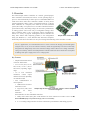
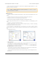
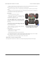
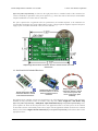
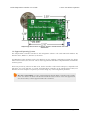
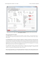
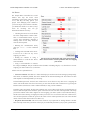
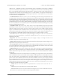
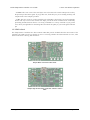
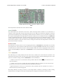
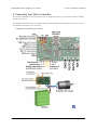
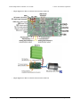
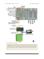
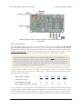
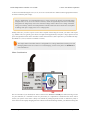
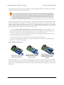
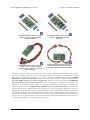
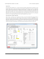
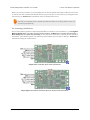
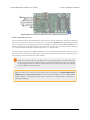
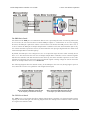
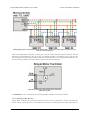
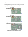
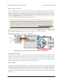
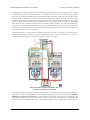
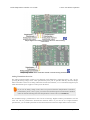
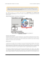
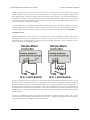
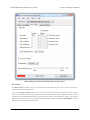
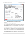
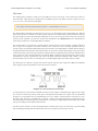
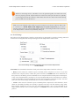
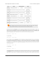
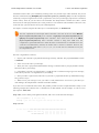
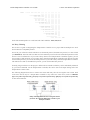
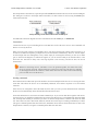
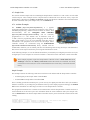
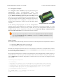
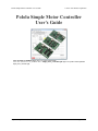
Pololu Simple Motor Controller User’s Guide
© 2001–2015 Pololu Corporation
RC Connections Overview
The RC connection block consists of two channels oriented as columns and a battery elimination circuit (BEC)
column for supplying power to the RC receiver. Each channel has a ground pin (outlined in black in the above
diagrams), a power pin (outlined in red in the above diagrams), and a signal pin (outlined in yellow in the above
diagrams). The RC signal pins can read standard hobby servo RC pulses with peaks anywhere from 2 to 5 V. The
included shorting block [https://www.pololu.com/product/968] can be used to supply the power pin row with either
3.3 V or 5 V, which in turn can be used to power an RC receiver.
Note: If you want to connect servos directly to your RC receiver, you must power it separately as
the Simple Motor Controller’s regulators cannot supply enough current to power a servo. If your
RC receiver is powered separately, you must leave the BEC jumper off to avoid shorting the motor
controller’s regulated voltage to your RC receiver’s power source. Your receiver and Simple Motor
controller must always have a common ground, even if you power the RC receiver separately.
The channel pins have a 0.1" spacing, which means that a female-female servo extension cable
[https://www.pololu.com/product/780] can be used to connect an RC receiver directly to the board.
Simple Wiring Example: Connecting to an RC Receiver
Wiring diagram for connecting an RC receiver to a Simple Motor Controller.
Using the RC Channels
The Simple Motor Controller is constantly reading the two RC channels and making the measured pulse widths
available via the USB and serial interfaces, even when the controller is not in RC mode. For example, you can
use the serial interface to read the RC channel values while the motor controller is in analog mode. The RC
channels are read with 0.25 µs resolution, and RC pulse frequencies from 10 Hz to 333 Hz are permitted. A
number of settings exist for adjusting what constitutes a valid RC signal.
Driving a Motor
In RC mode, the channel values are mapped to motor speed based on the channel calibration values and the
mixing mode. We recommend your first step after connecting your RC receiver be to use the Quick Input Setup
wizard in the Simple Motor Control Center. The wizard instructs you to move your transmitter control sticks
to their extremes and maps stick full forward/right to the maximum forward motor speed, the neutral stick to
speed zero, and the stick full back/left to maximum reverse speed. Calibration can have a significant impact on
performance.
4. Connecting Your Motor Controller
Page 40 of 108