1
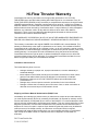
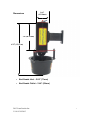
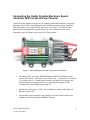
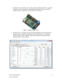
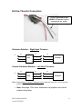
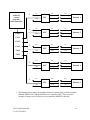
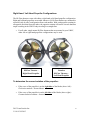
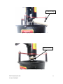
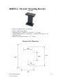
400HFS-L Hi-Flow Thruster
Product Guide and Warranty
Hi-Flow Thruster Warranty
CrustCrawler has a strong commitment to the high quality production of it’s HI-FLOW
THRUSTERS and to provide industry leading after-sales support for our customers. Every HIFLOW THRUSTER (GOODS) is fully covered by a comprehensive warranty to the original owner
(OWNER) against defects in materials or workmanship for a period of 1 month from the date of
shipment, whether or not use starts from that date. All claims under this limited warranty shall be
deemed waived unless received by CrustCrawler within 10 days of delivery if visibly damaged or
defective, and, otherwise, within 30 days after the defect to which each claim relates is
discovered. This is not an unconditional guarantee against all hazards or failures and the
Limitations and Exclusions listed below apply.
THIS WARRANTY IS EXPRESSLY IN LIEU OF ANY OTHER WARRANTIES EXPRESSED OR
IMPLIED, INCLUDING ANY IMPLIED WARRANTY OF MERCHANTABILITY OR FITNESS.
This warranty is extended to the original OWNER of the GOODS and is not transferable. This
warranty is limited solely to the repair or replacement, at our factory, of the defective GOODS.
CrustCrawler shall not be liable for any damage or harm, nor for any exemplary, special, punitive,
consequential or incidental damages, including but not limited to any loss of revenue, profit or use
resulting thereby. If a component is found to be defective during the period of this warranty,
CrustCrawler reserves the right to repair or replace the defective component or to refund the
original purchase price at its own discretion. In no event shall CrustCrawler be liable for more
than the original purchase price of the defective GOODS.
Limitations and Exclusions
This limited warranty does not cover:
•
•
•
•
•
Damage caused by improper use, improper maintenance, incorrect reassembly or
accidental damage
Items subject to normal wear including but not limited to surface finish, seals, motors,
gear box and cables unless found to be defective in workmanship or materials
Modification made to the HI-FLOW THRUSTER without prior authorization from
CrustCrawler Inc
Damage due to incorrect power connection as described in the User’s Manual
Damage or failure that is caused by acts of God, acts of war, or other such similar or
dissimilar occurrences beyond CrustCrawler's control.
Shipping and Return Material Authorization (RMA) Forms
Immediately upon identifying a problem which you believe to be subject to this limited warranty,
you must request warranty service by contacting CrustCrawler. All requests for warranty service
must be authorized by CrustCrawler prior to return of the GOODS. You must first attempt to work
with our technical support staff to help diagnose the problem. This may include performing routine
diagnostic procedures. The technician can determine if the problem can be resolved over the
telephone or if return for repair is required. Upon determining that the product may be defective
under the terms of the limited warranty, and that return to the repair facility is required,
CrustCrawler will issue an RMA number which you must complete and return to CrustCrawler.
Upon receipt of the RMA number, the GOODS can then be shipped to CrustCrawler for
evaluation.
2015 CrustCrawler Inc.
V 6.0 05/19/2015
2
Do not return the GOODS to CrustCrawler prior to the receipt of the RMA number. The GOODS
must be shipped in their original shipping containers and packing material or otherwise
adequately packed for shipment, and the RMA number must appear clearly on the outside of the
package. If the product is damaged during shipment or received in inadequate packaging, this
warranty may not apply.
For warranty shipping, the OWNER is responsible for shipment of all GOODS to CrustCrawler
and CrustCrawler will cover the costs of return shipment of GOODS to the OWNER up to $90.00
USD maximum.
In all cases the OWNER is liable for damage to the GOODS that may occur during shipment and
should consider insuring the shipment both to and from CrustCrawler.
2015 CrustCrawler Inc.
V 6.0 05/19/2015
3
CrustCrawler “High Flow 400HFS-L” Series AUV/UROV
Thruster Technical Specifications
CrustCrawler’s “High Flow” AUV / UROV 400HFS-L thrusters where designed to be a
reliable and customizable thruster for light duty UROV / ROV requirements. No other
thruster on the market has the programmable flexibility to set specific operating
parameters for different environmental conditions than the CrustCrawler “High Flow”
series.
Motor Specifications
•
•
•
•
•
•
•
Motor Type – High efficiency brushless
Weight – 185g. (6.5oz)
Gear Ratio – 4.28:1
Shaft Diameter – 5.0mm (.1969”)
Maximum Case Temperature – 100C (212F)
Operating Voltage – 12 to 50 volts
Operates in forward and reverse thrust
Connector Specifications
•
•
Depth Rating – 300 ft.
3 wire
Thruster Housing / End Caps
•
T- 6 Aluminum
Thruster Seal
•
•
Motor - Flexible, polyurethane encapsulating compound
Shaft Seal – Custom Lip Seal followed by encapsulating grease gallery
Thruster Weight
•
•
Weight in air - 1 pound (.453kg)
Weight in Water – 9 ounces (255 grams)
Thruster Length
•
6.25” (15.87cm)
Finish
•
Black / Red Type II Hard Anodized Finish
Propeller
• Size – 2.36”” (60mm) - 4 blade
• Material – Solid Brass
• Propeller Adapter – Machined aluminum / Anodized Type II Black
2015 CrustCrawler Inc.
V 6.0 05/19/2015
4
Kort Nozzle Adaptor
• Material – .090 Aluminum
• Offset - 120 degrees
Thrust Rating
•
•
•
1 – 6 pounds (.45 to 2.72kg) normal operating range ((approximately 140W to 180W
max)
7 - 10 pounds (3.17 to 4.53kg) max burst thrust*
Note# 1 – Burst thrust is defined as the thruster range for short periods of time of less
than 20 seconds
2015 CrustCrawler Inc.
V 6.0 05/19/2015
5
A Note about Throttle Settings and Maximum Power of the Thruster
Whatever throttle you choose to use (computer, joystick etc.) with the 400HFS-L Hi-flow
Thruster it is important to note the following:
1. Once you complete the calibration routine of the throttle device you are using with the
Phoenix ESC ESC’s it is important to note that your full throttle settings DO NOT
DIRECTLY relate to the maximum power rating of the thruster! Always calibrate your
throttle position to ensure they are within the operating parameters of the thruster.
•
Failure to do so will result in thermal damage to the 400HFS-L thruster motor!
•
The 400HFS-L thrusters are equipped with a thermally conductive heat sink compound
around the thruster motor to keep the thruster motor running cool within its operating
thrust range. The 400HFS-L is designed to run with a burst thrust of 7- 10 pounds of
thrust maximum for short periods of time (max 20 seconds recommended). As a general
rule, always ensure that you do not overheat the thruster when running the units for long
periods of time.
2015 CrustCrawler Inc.
V 6.0 05/19/2015
6
Dimensions
1.66”
(42.19mm)
3.4”(86.87mm)
6.25” (15.87cm)
• Kort Nozzle Inlet – 2.80” (71mm)
• Kort Nozzle Outlet – 2.44” (62mm)
2015 CrustCrawler Inc.
V 6.0 05/19/2015
7
Safety
•
Always unplug the Hi-Flow thruster before handling the propeller in any way.
•
Always practice safe electrical handling and safety practices when working
around water.
Break-In Period
The Hi-Flow thruster can be run at any speed right out of the box fully submersed.
However, do not run the Hi-Flow thruster out of the water at high speeds for longer than
30 to 60 seconds or overheating and possible damage can occur.
Thruster Control
Any brushless motor control software / hardware can be used to operate the Hi-Flow
thrusters. CrustCrawler offers a specifically engineered Phoenix ESC controller from
Castel Creations which has special firmware developed especially for the Crustcrawler
series of ROV thrusters. We have also have a suggested control diagram in this manual
for thruster control as an option. However, thruster control is up to you our customer.
2015 CrustCrawler Inc.
V 6.0 05/19/2015
8
Connecting the Castle Creation Electronic Speed
Controller (ESC) to the Hi-Flow Thruster
CrustCrawler has engineered a special UV resistant, potted and completely waterproof
housing for the Castle Creations Phoenix ESC (brushless electronic speed controller).
This design allows you to bolt the ESC directly to your UROV. All of the Hi-Flow
thrusters have been internally wired the same way, so the diagrams shown on the
subsequent pages will apply to any series of Hi-Flow thruster.
Figure 1 – Phoenix EDG ESC Controller (non-potted version shown)
•
The Phoenix ESC uses Pulse Width Modulation (PWM) for brushless motor
control (full forward - 2ms square wave, full reverse – 1ms square wave, neutral
1.5 ms square wave).. Customization of throttle and brake curves along with
forward and reverse characteristics can be programmed using the Castle
Creations Castle Link USB programming kit.
•
Each thruster will require (1) ESC. Do not attempt to connect and control (2)
thrusters with (1) ESC.
•
Any brushless speed controller with a rating of at least 20 amps with reverse
capability can be used with the 400HFS-L Thruster.
2015 CrustCrawler Inc.
V 6.0 05/19/2015
9
Best Practices
•
Ensure that you provide a solid, soldered connection when connecting the ESC to
the thruster. Also, when using the enclosed shrink tubing, ensure that the tubing
is sealed on the inside and the outside to ensure a waterproof seal. (“Liquid Tape”
or other liquid sealants that dry to a hard waterproof encasement will work).
•
Always use wires that are equal to or greater in thickness than the wires on the
thruster and ESC!
•
The Phoenix ESC’s are not meant to propagate a signal through long lengths of
wire. As a best practice, the Phoenix EDGE ESC’s should be within 1 to 10 feet
of the thrusters (depending on wire size used). Longer lengths of wires can be
used between the thrusters and the ESC’s but performance will have to be
monitored.
2015 CrustCrawler Inc.
V 6.0 05/19/2015
10
•
A Pololu Servo Controller can be used to attach each Phoenix ESC to a specified
channel to control each thruster independently with either software, joystick
control or both. A single PSC can control up to 18 thrusters.
Figure 2 - Polulo Servo Controller
•
The Pololu servo controller generates the PWM signals needed by the Phoenix
brushless motor controllers for throttle control. The Pololu servo controllers
software can be used as a throttle control for the thrusters using its powerful
control software as shown below.
2015 CrustCrawler Inc.
V 6.0 05/19/2015
11
•
For more detailed information on the operating parameters and wiring
characteristics of the Castle Creations Phoenix ESC, be sure to read the enclosed
documentation that came with your ESC.
Power / Signal Connection
(+)
Signal cable
from
controller
(PWM only)
(-)
Note: Phoenix EDGE ESC’s, require 5V on the brown(-) and red wires(+)). The orange
wire is for the PWM signal.
2015 CrustCrawler Inc.
V 6.0 05/19/2015
12
Hi-Flow Thruster Connection
3-wire Connections to the
400HFS-L Thruster (Can be
connected in any order)
Clockwise Rotation – Right Hand Thrusters
+
Red
PWM
Black
ESC
Red
Red
Black
Blue
White
White
Thruster
_
Counter-Clockwise Rotation – Left Hand Thrusters
+
Red
PWM
Black
ESC
Red
Red
White
Blue
Black
White
Thruster
_
Note: Swapping any (2) of the (3) thruster wires connected to the ESC will reverse the
rotation of the propeller.
• Note: See page 12 for more information on propeller and correct
rotation information
2015 CrustCrawler Inc.
V 6.0 05/19/2015
13
Software
control
program /
microcontroller
+
Red
PWM
Black
ESC
Red
Red
Black
Blue
White
White
Red
Red
Black
Blue
White
White
Red
Red
Black
Blue
White
White
Red
Red
Black
Blue
White
White
Red
Red
Black
Blue
White
White
Thruster 1
_
+
Pololu
Red
PWM
Black
ESC
Thruster 2
_
Ch #1
Ch #2
Ch #3
Ch#4
+
Red
PWM
Black
ESC
Thruster 3
_
Ch#5
+
Red
PWM
Black
ESC
Thruster 4
_
+
Red
PWM
Black
ESC
Thruster 5
_
•
The diagram above depicts an example of thruster control using a Castle creations
Phoenix EDGE (ESC) and the Pololu Servo Controller (PSC). This is just one
example of many ways of which you can control the 400HFS-L thruster.
2015 CrustCrawler Inc.
V 6.0 05/19/2015
14
Throttle Calibration of the Castle Creations Phoenix ESC
When the Castle creations Phoenix ESC is first connected to the Hi-Flow 400HFS-L
thruster, the Phoenix must be calibrated to your throttle. The “throttle” used can take
many forms but is not limited to:
•
•
•
Software Throttles
Joysticks
Sliders
Once the Phoenix ESC is calibrated to each thruster, there is no need to calibrate the
Phoenix ESC again unless you have changed to a different type of throttle.
Calibration Steps
The Phoenix manual has basic steps on how to calibrate the Phoenix to your throttle. We
have summarized those steps below. Before proceeding with the steps below, ensure that
your Phoenix ESC is solidly connected (soldered and insulated) to your 400HFS-L
thruster and you have the proper power connections.
Step 1
With power off to your Phoenix ESC , move your throttle to full forward throttle
Step 2
Turn on the power to your Phoenix ESC . You will hear a series of short “beeps”
followed by a steady series of beeps.
Step 3
Once there is a steady series of beeps, move your throttle to full reverse throttle. You will
hear a series of short beeps followed by a steady series of beeps.
Step 4
Once there is a steady series of beeps, move your throttle to neutral or center. There will
be a series of short beeps followed by silence. Your Phoenix ESC ESC is now calibrated
to your throttle.
Caution! Always remember to ensure your throttle setting is in the neutral position when
powering on your Phoenix ESC ESC’s. Failure to do so could result in the thruster
running at the current throttle setting or the Phoenix ESC going back into calibration
mode.
2015 CrustCrawler Inc.
V 6.0 05/19/2015
15
A Note about Throttle Settings and Maximum Power of the Thruster
Whatever throttle you choose to use (computer, joystick etc.) with the 400HFS-L Hi-flow
Thruster it is important to note the following:
• Once you complete the calibration routine of the throttle device you are using with the
Phoenix ESC ESC’s it is important to note that your full throttle settings DO NOT
DIRECTLY relate to the maximum power rating of the thruster! Always calibrate your
throttle position to ensure they are within the operating parameters of the thruster.
•
Failure to do so will result in thermal damage to the 400HFS-L thruster motor!
2015 CrustCrawler Inc.
V 6.0 05/19/2015
16
Right Hand / Left Hand Propeller Configurations
The Hi-Flow thrusters come with either a right hand or left hand propeller configuration.
Right and left hand propellers are needed whenever (2) Hi-flow thrusters are mounted in
a parallel (side by side) configuration from each another. With each propeller rotating in
an opposite direction from each other, the opposite rotation will cancel out each thrusters
torque resulting in the UROV body traveling in a straight line.
•
For all other, single mount Hi-Flow thrusters that are mounted in your UROV,
either left or right hand propellers configurations may be used.
Clockwise Rotation
Hi-Flow Thruster –
Right Hand Propeller
Counterclockwise
Rotation
Hi-Flow Thruster –
Left Hand Propeller
To determine the correct rotation of the propeller:
•
If the curve of the propeller is on the right sides of the blades (above left) –
Clockwise rotation = forward thrust
•
If the curve of the propeller in on the left sides of the blades (above right) –
Counterclockwise rotation = forward thrust
2015 CrustCrawler Inc.
V 6.0 05/19/2015
17
Important! Please Read!
Important Information about the proper operation and care of the
Hi-Flow 400HFS-L Thruster
CrustCrawler’s Hi-Flow series of thrusters are designed to be a rugged, affordable choice
for all types of AUV/ROV applications. To ensure many hours of reliable use, the best
practices listed below will ensure a long service, free life of the thruster motor and
gearbox.
Operating Best Practices
•
The gearbox in the 400HFS-L thruster is built extremely strong but as a best
practice abrupt and full speed thruster changes of rotation should be avoided.
•
NEVER attempt to remove the propeller assembly from the motor shaft.!!
Attempting to remove the prop assembly from the motor shaft can permanently
damage other components of the thruster.
•
NEVER leave the thruster soaking in water when not in use.
•
Always re-grease the grease gallery after every use. Failure to do so can leave
water in the grease gallery which can lead to damaged thruster components.
•
Before applying grease to the grease gallery after use, tilt the thruster to 30 –
45 degrees and run for 40 – 60 seconds to ensure most of the water is purged
from the grease gallery
•
NEVER run the Hi-Flow thruster out of the water at full throttle. Always run the
thruster out of the water (for testing etc) at 50% max of full throttle for no longer
than 40 -60 seconds at a time., The 400HFS-L is designed to run in the water not
out of the water.
•
If your thrusters where used in salt water, always rinse the entire thruster,
especially the front of the motor and prop assembly with fresh water after each
use and re-grease the grease gallery.
•
Ensure that you provide a solid, soldered connection when connecting the ESC to
the thruster. Always use shrink tubing and a good sealant compound to ensure
that each connection is sealed and waterproof (“Liquid Tape” is an excellent,
fast drying sealant that can be purchased at most hardware stores).
2015 CrustCrawler Inc.
V 6.0 05/19/2015
18
•
Always ensure that water has been purged from the grease gallery of the
thruster after each use and re-greased.
2015 CrustCrawler Inc.
V 6.0 05/19/2015
19
Applying Grease to the Grease Gallery
1. Remove the grease screw as shown in figure 1.
2. Apply the white lithium grease using the supplied grease syringe until excess
grease begins to emerge from between the prop adapter and grease gallery fitting.
3. Rotate the propeller 5 complete turns
4. Repeat steps 1 -2
5. Re-install the grease screw
Grease Screw
Figure 1 - Remove Grease Screw
2015 CrustCrawler Inc.
V 6.0 05/19/2015
20
Grease Syringe
Figure 2 - Apply grease using grease syringe
Excess Grease
Figure 3 - Apply grease until excess grease emerges
2015 CrustCrawler Inc.
V 6.0 05/19/2015
21
Note: White Lithium grease is supplied to thruster orders of (3) units or more. If you are
using your own grease, be sure to clean out the existing grease before applying a different
type of marine grease or equivalent to the grease gallery as some grease can react to other
grease types.
2015 CrustCrawler Inc.
V 6.0 05/19/2015
22
400HFS-L Thruster Mounting Bracket
(Optional)
•
•
•
•
•
Material – Machined 6061 T6 Aluminum
Finish – Hard Anodized Black
Mounting Screws – Quantity (6) - 4/40 (#4) – 1” (2.54cm)
Thruster Mounting Screws – Quantity (4) - Stainless Steel 4/40 (#4) – 3/8”
mounting screws
Bracket / Kort Nozzle Clearance - .31” (7.8mm)
Mounting Hole Dimensions
2015 CrustCrawler Inc.
V 6.0 05/19/2015
23
Figure 3 - 400HFS-L Thruster with Mounting Bracket
•
Use the supplied stainless steel, #4 (3/8”) mounting screws to attach the thruster
mounting bracket to the body of the thruster.
•
Use a thread-locker type of sealant (like “Loctite or equivalent) for each of the (4)
screws when mounting the bracket to the thruster.
2015 CrustCrawler Inc.
V 6.0 05/19/2015
24
Support
Support, should you need, it is available in 2 ways:
Forums - http://forum.crustcrawler.com/phpBB3/index.php
Phone – 480-577-5557
We strongly suggest questions dealing with control software, wiring and other related
configuration information be posted on our forums. We use the forums to post code
samples, wiring diagrams and pictures to help resolve customer questions quickly and
efficiently.
Remember, we can’t see your code or wiring over the phone, but we can see it using our
forums! Please visit our web site frequently as we will be releasing more software and
accessories in the coming months for our line of UROV and ROV products.
2015 CrustCrawler Inc.
V 6.0 05/19/2015
25