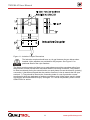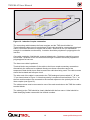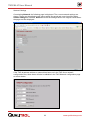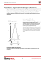
1
User Manual
TWS Mk VI
Travelling Wave Fault Locator
Document ID: 40-08534-02
www.qualitrolcorp.com
Table of Contents
1.
Health & Safety at Work etc. Act 1974 Section 6.1© ........................... 1
2.
Overview ................................................................................................ 2
3.
Introduction ........................................................................................... 2
3.1.
Standard Equipment ..................................................................................... 2
3.2.
Typical Scheme............................................................................................. 3
3.3.
Control Room Equipment/Software ............................................................ 3
3.4.
Transport and Storage conditions .............................................................. 3
3.5.
Mechanical Characteristics of TWS ............................................................ 4
3.6.
Climatic Conditions ...................................................................................... 4
3.7.
Electrical Conditions of TWS ....................................................................... 4
3.7.1.
3.8.
4.
Power supply, consumption and earthing requirements ..................................... 4
Hardware Overview....................................................................................... 5
Installation ............................................................................................. 8
4.1.
Mounting the TWS ........................................................................................ 8
4.2.
The Supply Voltage....................................................................................... 8
4.3.
The Link from the TWS Internal Modem to the Telephone Line................ 9
4.4.
Connection to External Serial Port COM 2.................................................. 9
4.5.
Connecting Ethernet................................................................................... 10
4.6.
Connecting the Inductive Couplers (Transducers) .................................. 10
4.7.
Inductive Coupler Polarity.......................................................................... 13
4.8.
Optional Mounting Board for CTs ............................................................. 14
4.9.
The GPS Antenna........................................................................................ 15
4.10. Alarms.......................................................................................................... 17
5.
TWS Commissioning .......................................................................... 18
5.1.
Commissioning Steps ................................................................................ 18
5.2.
Visual Inspection ........................................................................................ 18
5.3.
Initial Switch On .......................................................................................... 18
5.4.
TWS Status LEDs........................................................................................ 19
5.5.
The “config.tws” file. .................................................................................. 20
5.6.
Description of “config.tws” file contents.................................................. 20
5.7.
TWS Webpage Configuration Tool ............................................................ 21
5.7.1.
Adjust TWS Configuration ................................................................................. 22
5.7.2.
Manage TWS .................................................................................................... 33
5.8.
Remote Communications........................................................................... 36
Contents i
www.qualitrolcorp.com
Table of Contents
5.9.
Analogue Line Operation ........................................................................... 37
5.10. Check Alarm Operation .............................................................................. 37
5.10.1.
Power Supply ................................................................................................... 37
5.10.2.
GPS Fail Alarm ................................................................................................ 38
5.10.3.
Watchdog ......................................................................................................... 38
5.10.4.
Trigger Alarm ................................................................................................... 38
5.10.5.
Operational Checks.......................................................................................... 38
5.11. Installation of Additional Line Modules .................................................... 38
Appendix A – Installing an External Modem.............................................. 40
Appendix B - Upgrading a TWS .................................................................. 42
Appendix C – Telephone line simulator ..................................................... 45
Appendix D – TWS Mark V DNP Option...................................................... 46
Appendix E – Type E Test to Energise a Dead Line .................................. 50
Contents ii
www.qualitrolcorp.com
TWS Mk VI User Manual
1.
Health & Safety at Work etc. Act 1974 Section 6.1©
This product is checked and supplied in accordance with our published specifications and
used in normal or prescribed applications and within the parameters set for mechanical and
electrical performance, will not cause danger or hazard to health or safety, provided that
normal engineering and safety practices are observed and the product is only used by
trained and qualified persons.
All usage of this product must be in accordance with this manual if there is any doubt about
any aspect relating to the correct use of the product please contact:
QUALITROL® Instruments
15 Wildflower Way
Belfast
BT12 6TA
Northern Ireland
Telephone: +44 (0) 2890 225200
Fax: +44 (0) 2890 225225
This operator’s manual is published by QUALITROL for use with the TWS instrument
described herein. QUALITROL reserves the right to revise this manual without notice for any
reason. This includes but is not limited to the utilisation of advances in technology, and
changes in the instrument or its configuration. Liabilities for difficulties arising from unknown
or unforeseen technical limitations are disclaimed.
1
www.qualitrolcorp.com
TWS Mk VI User Manual
2.
Overview
This document is split into three main sections. The first section titled “Introduction” gives a
brief overview of a TWS (Travelling Wave System) followed by a description of the hardware
characteristics of a TWS. The second section titled “Installation” describes the steps taken
to physically install a TWS. The third section titled “TWS Commissioning and Testing”
involves configuring the TWS software and finally testing the fully installed unit.
3.
Introduction
The TWS is designed to accurately locate faults on high voltage, overhead line feeders that
may include lengths of cable. It can give useful results on more complicated networks
including some branches.
The preferred location is a substation where more than one feeder is connected to the
busbar. The TWS depends on the measurement of current transients on the secondary side
of the main protection current transformer. This method can only be applied at points on the
system where current transformers are available.
At substations where only one feeder connects to a transformer it will be necessary to
measure voltage transients from a suitable voltage transducer. Contact QUALITROL for
further details on measuring voltage transients.
3.1. Standard Equipment
As shown in Figure 1a and 1b below a standard TWS comes equipped with: (a) One TWS chassis with: internal power supply, solid state flash drive, CPU Card, GPS module, modem and line
modules (maximum of 8). There are also external connections for RJ45 Ethernet, four alarm
outputs, IRIG B time synchronisation output and a serial port.
(b) GPS antenna with a ten meter lead (extension cables are available, see section 4.9)
(c) Split core inductive couplers and associated nylon washers, nuts and screws. (3
inductive couplers for each line module)
(d) Lightning surge protection device
(e) Telephone connection cable
(f) Linux operating system and the latest TWS firmware.
Figure 1a and 1b
2
www.qualitrolcorp.com
TWS Mk VI User Manual
3.2. Typical Scheme
Figure 2 below is a typical scheme of two TWSs installed at either end of an overhead line.
Each TWS monitors the current transients on phase A, B and C of the overhead line
feeders. The main PC is usually situated in the control room and is used to retrieve
timestamps of current transients from both TWSs at either end of the line and calculates
distance to fault.
Figure 2 – Typical Scheme
3.3. Control Room Equipment/Software
The required control room equipment consists of a PC running Windows 2000 or XP.
The control room PC should have the following: •
Modem hardware installed (if modem connection option is selected)
•
Ethernet port available (if LAN connection option is selected)
•
TWSBase2000 software installed (for further information consult the TWSBase2000
user manual)
•
Network Editor software installed (for further information consult the TWSBase2000
user manual)
•
Poll and Display software installed (optional, for further information consult the PAD
user manual)
3.4. Transport and Storage conditions
A storage temperature of -40 to +70 oC is acceptable. The equipment must be kept dry. The
packing provided is suitable for road and air freight.
3
www.qualitrolcorp.com
TWS Mk VI User Manual
3.5. Mechanical Characteristics of TWS
Enclosure
Width
Depth
Height
Weight
6U, 19” rack mountable chassis
448.8mm (17.68”)
386mm (15.21”)
266.7mm (10.5”)
18kg (40 lbs)
3.6. Climatic Conditions
The operating temperature range is 0 to +55oC, relative humidity from 5% to 95% noncondensing.
3.7. Electrical Conditions of TWS
3.7.1. Power supply, consumption and earthing requirements
The input voltage will depend on power supply option at time of purchase.
The two power supply options are:
Unit A
This unit is designed for nominal 48V dc battery supplies. The Substation Module operates
to specification on this unit for dc supplies in the range 48V(-20% to + 10%).
Maximum Power Consumption if fully equipped is 120W.
Unit B
This unit is designed for dc supplies operating within the limits 80 to 240V, or 50/60Hz ac
supplies within the voltage range 90to 250V.
Maximum Current Consumption if fully equipped is 120W.
Unit B allows the equipment to be used on ac supplies, which may be useful for
test purposes. However, in the interests of supply reliability, we strongly
recommend you normally operate the equipment on dc storage battery supplies.
4
www.qualitrolcorp.com
TWS Mk VI User Manual
3.8. Hardware Overview
The following section illustrates the TWS hardware from different angles.
Figure 3 – Front view of TWS
Figure 4 - Rear view of TWS
5
www.qualitrolcorp.com
TWS Mk VI User Manual
Figure 5 - Detailed rear view of TWS
6
www.qualitrolcorp.com
TWS Mk VI User Manual
Figure 6 – Internal view of TWS
7
www.qualitrolcorp.com
TWS Mk VI User Manual
4.
Installation
On receipt of the equipment and accessories they should be examined for any damage or
shortages which should be immediately reported to QUALITROL.
Installation of the TWS consists of: a. Mounting the TWS in a suitable 19” rack.
b. Connecting the supply voltage to the TWS.
c. Linking the TWS to a telephone line (Lightning surge protection device) if applicable.
d. Connecting an external modem if applicable.
e. Connecting the TWS to the local area network using the twisted pair Ethernet port if
applicable.
f. Connecting the split core CTs to the secondary (protection) wiring.
g. Attaching and positioning the GPS antenna.
h. Connecting output alarms.
4.1. Mounting the TWS
The TWS has a 19 inch rack mount form factor with 2 mounting holes to the far left and 2
mounting holes to the far right on the front of each unit.
4.2. The Supply Voltage
Check that the voltage of the proposed supply matches the voltage of the TWS model
ordered. If it matches connect the supply voltage to the polarity labelled connections marked
SUPPLY or 48 VDC at the rear of the TWS as shown in figure 7 below. A provision for
earthing the unit is provided by the stud connection marked at the rear of the TWS. The
Earth connection should be made by 6mm2 tri-rated earth cable.
Figure 7 - Supply Voltage
8
www.qualitrolcorp.com
TWS Mk VI User Manual
4.3. The Link from the TWS Internal Modem to the Telephone Line
As shown in figure 8 below the telephone line is connected to the internal modem via a data
surge protection device.
Figure 8 - Connecting Telephone line to data surge protection device
4.4. Connection to External Serial Port COM 2
The external serial port com 2 may be used either for an external modem (see appendix A)
or for a DNP connection (see appendix D) to interface to a Scada system. A standard
modem cable can be used to connect the external modem to the “Com port 2” on the rear of
the TWS. Figure 9 below shows the pin assignment on “Com port 2”.
Pin
1
2
3
4
5
6
7
8
9
Signal name
Data Carrier Detect (DCD)
Receive Data (RX)
Transmit Data (TX)
Data Terminal Ready (DTR)
Signal Ground (GND)
Data Set Ready (DSR)
Request to Send (RTS)
Clear to Send (CTS)
Ring Indicator (RI)
Figure 9 - External serial port COM 2 connections Pin Assignments
The external serial port com 2 may be used either for an external modem or for
a DNP connection to interface to a Scada system. The DNP feature may be
enabled by web page, see section 5.7.1.
9
www.qualitrolcorp.com
TWS Mk VI User Manual
4.5. Connecting Ethernet
An Ethernet connection is available at the rear of the TWS. The TWS is assigned the default
IP address of 10.75.8.46 when it leaves the factory. The IP address can be re-configured
using the built in web page feature described in section 5.4 of this manual. See location of
TWS ethernet port in figure 5.
The Web Page can be accessed via modem or Ethernet.
4.6. Connecting the Inductive Couplers (Transducers)
The inductive couplers are shown in Figure 10 and 11 as shown below:
Figure 10 - Inductive Couplers with polarity dots
It is important to match the polarity dots of the two sections of the linear coupler
when fitting as shown.
10
www.qualitrolcorp.com
TWS Mk VI User Manual
Figure 11 - Inductive Coupler Dimensions
The inductive couplers should have an ‘air gap’ between the two halves when
installed. Nylon washers are provided for this purpose. See Figure 11 for
positional detail of the nylon washers
The linear couplers need to be fitted one on each phase around the secondary wiring from
the protection current transformers associated with the line being monitored. They need to
be fitted consistently facing the same direction on each phase to meet the direction (polarity)
convention. It has been accepted that the positive direction of view is towards the line (see
section 4.7). They should be fitted to the connecting leads of a set of protection current
transformers which are dedicated to feeding a protection relay (digital relays result in better
signals than electromechanical relays). See figure 12. If this is not possible, please consult
QUALITROL for advice.
11
www.qualitrolcorp.com
TWS Mk VI User Manual
Figure 12 - Inductive Coupler connection
The connecting cable between the linear couplers and the TWS should either be:
Three individual cables (one for each phase). Each cable should be a screened twisted pair
cable. Conductors should be of copper and at least 7 strand 0.25 mm (for mechanical
strength in a substation environment). Insulation should be polythene or polypropylene for
low loss.
One cable containing 3 individually screened twisted pairs. Conductors should be copper
and at least 7 strand 0.25 mm for mechanical strength. Insulation should be polythene or
polypropylene for low loss.
The three core cable is preferred.
Terminal blocks are provided to fit the cable to the linear coupler secondary connections.
Alternatively the cable can be soldered directly onto these connections and a low
temperature heat shrink sleeve fitted to match the cable size being used. The cable screens
should be insulated and left open circuit.
The other end of the cable is connected to the TWS analogue inputs marked “A”, “B” and
“C” as shown below in Figure 13. Note that polarity is marked on terminal block. The ‘+’ at
the line module needs to be connected to the terminal adjacent to the ‘polarity dot’ on the
linear coupler (see figure 10).
The cable screens must be connected to one of the earth terminals on the TWS line module
terminal blocks.
The cable(s) at the TWS should be clearly labelled with the line name. A label should be
fitted identifying feeder names with line module numbers.
12
www.qualitrolcorp.com
TWS Mk VI User Manual
A
B
C
Phase ‘A’ Inductive Coupler
Phase ‘A’ Screen
Phase ‘B’ Inductive Coupler
Phase ‘B’ Screen
Phase ‘C’ Inductive Coupler
Phase ‘C’ Screen
Figure 13 - View of physical analogue channel connections
The length of cable between the inductive couplers and the TWS should be no
longer than 25m. Contact QUALITROL if longer cable runs are required. The
screen is earthed at the TWS end only. Observe the polarity: dot on linear
coupler to + on TWS
4.7. Inductive Coupler Polarity
Care should be taken to maintain polarities so that the phasing of connections from the
current transformers to TWS is known. The split core inductive couplers are installed without
circuit outages. The inductive couplers allow travelling waves to be recorded but attenuate
the 50/60Hz components.
The convention is to install inductive couplers looking into the line (as described in section
4.7). Figure 14 show an “in zone” fault. The inductive couplers in this example are installed
in such a way that they are looking into the line. The resulting transients recorded by the
TWSs at either end of the line (shown in green) then have the same polarity.
Figure 14 - Fault occurring on the line being monitored by the TWS
Figure 15 shows an “out of zone” fault again with both the inductive couplers installed at
each end of the line looking into the line. The resulting transients recorded by the TWS this
time have opposite polarities.
13
www.qualitrolcorp.com
TWS Mk VI User Manual
Figure 15 - Fault occurring outside the line being monitored
4.8. Optional Mounting Board for CTs
If requested the CTs can be attached to an optional mounting board rather than the usual
loose installation. Figure 16a and 16b shows how the CTs are fastened to the mounting
board. Note if the CTs are installed in this manner then it will be necessary to open circuit
the CT wiring to allow connection to the screw terminals on board located at P2
Figure 16-a - Optional CT Mounting Board
Figure 16-b - P1 Secondary outputs
14
www.qualitrolcorp.com
TWS Mk VI User Manual
4.9. The GPS Antenna
Link the GPS antenna to the connection on the rear of the TWS.
There are a number of GPS satellites in different orbits, and at any time, the antenna must
be able to lock on to four of them for accurate time synchronisation. This means that the
requirements for a GPS antenna are very different from that of a satellite antenna for
domestic use which is a directional antenna looking at one satellite in a geostationary orbit.
The GPS antenna therefore needs to be installed in a position where it can see as much as
possible of the sky. See figure 17 for an antenna placement guide. The antenna is provided
with a 10m connecting cable terminated in the correct BNC plug to fit the GPS
antenna socket on the rear panel. The antenna is mounted on a 25mm mast and
should be placed with as much visibility to open sky as possible. If necessary, the
cable can be extended with up to a maximum of 30m of RG6 cable. Longer cable runs
require in-line amplification. For further detail, please contact QUALITROL.
Figure 17 - GPS Antenna placement guidelines
15
www.qualitrolcorp.com
TWS Mk VI User Manual
Figure 18 - GPS Antenna
Screws into Antenna
Screws tighten onto pipe
Insert 25mm diameter pipe
to a depth of 25mm
Figure 19 - Adapter for GPS Antenna
Mounting Plate 23.2 cm x 26cm. Mast height 65cm without antenna adapter fitted.
Figure 20 - Optional Antenna Mounting Kit
16
www.qualitrolcorp.com
TWS Mk VI User Manual
4.10. Alarms
The CPU board provides isolated contacts, which provide four alarms via the substation
alarm system, or for other purposes.
The contacts are isolated to a 6kV test voltage between coil and contacts, and 1.5kV
between contacts. The contacts are rated to switch:
•
Currents up to 8A at 250V ac
•
Currents up to 8A at 30V dc in a non inductive circuit
•
Currents up to 250mA up to 250V dc in a non inductive circuit
The matching plug is supplied with the unit.
The connections of the 4 contacts are shown in Fig 20.
A closed contact denotes an alarm condition.
To Telephone Socket
GPS Fail Alarm Contacts
Power Fail Alarm Contacts
Watchdog Alarm Contacts
Trigger Alarm Contacts
Figure 20 - Alarms and Modem Interface
There are many travelling waves on a transmission system that are not
generated by system faults but can cause a TWS to trigger. Not all the events
signalled by the Trigger Alarm contact indicate fault activity
17
www.qualitrolcorp.com
TWS Mk VI User Manual
5.
TWS Commissioning
5.1. Commissioning Steps
After a TWS has been installed there are a number of commissioning steps required to
ensure the TWS is primed and ready to record faults. The following steps should be
performed on the TWS following the physical installation steps taken in section 4 of this
manual
•
Visual inspection
•
Initial switch on
•
Checking TWS LED status
•
Using TWS web page to edit config.tws file
•
Using TWS web page to edit TWS IP address.
•
Testing Dial up connection
5.2. Visual Inspection
Open the TWS front panel by releasing the quick release clips at the top and lowering it
down on the bottom hinges.
Check that all the circuit boards and connectors are in place and have not become
dislodged in transit.
5.3. Initial Switch On
Having installed all the auxiliary equipment, and become familiar with the positions of the
various indications and controls commissioning can begin.
Check the voltage is within the power supply limits and apply power to the TWS.
The Power Status LED should show green indicating that the supply voltage is on.
If the Power Status LED does not show green then:
(a) Check that the voltage supply which feeds the TWS is switched on.
(b) Check that the correct voltage is available on the supply terminals of TWS.
If none of these checks reveal any problems contact QUALITROL for further advice.
18
www.qualitrolcorp.com
TWS Mk VI User Manual
5.4. TWS Status LEDs
On the TWS front panel there is a set of three indicator LEDs as shown in Fig 21.
•
The top one labeled “Power” indicates that the power supply is on. It is linked to the
alarm contacts available on the back panel. When the light is out the corresponding
alarm contact at the back of the instrument is closed.
•
The middle one labeled “GPS Locked”. When the light is on it indicates that the
internal GPS Module has acquired satellites (or LOCK). When the light is out the
corresponding alarm contact at the back of the instrument is closed.
•
The bottom one labeled “Watchdog” is an alarm, which indicates that TWS software in
the TWS has failed. When it is ON, the corresponding alarm contact on the back of the
instrument is closed.
Figure 21 TWS Indicator LEDs
The Watchdog will come on for a short time (several minutes) on power up. This
is normal behavior
The TWS also has a Dongle LED. It can be found on the rear panel of the unit as shown in
figure 22 below. This LED indicates that the TWS is in a healthy state. When the TWS
software is running and the unit is in a healthy state the Dongle LED will flash at a rate of
once every second. If the TWS software is not running the Dongle LED will be extinguished.
Figure 22 - Dongle LED
19
www.qualitrolcorp.com
TWS Mk VI User Manual
It will take several minutes after power up (similar to the watchdog) for the
dongle LED to start flashing. This is normal behaviour.
5.5. The “config.tws” file.
Each TWS MkVI unit contains a file called “config.tws”. An example of the default
“config.tws” file is shown below left along with the file format below right. It is necessary to
synchronise the names given to the line modules in the TWSBase2000 software with the
names given to the line modules in the “config.tws” file. This section describes the
correlation between the TWSBase2000 software and the “config.tws”.
File format
Sub-Station Name, TWS Name, 0, 0
Title, Subdirectory, Gain, Sampling Frequency
Title, Subdirectory, Gain, Sampling Frequency
Title, Subdirectory, Gain, Sampling Frequency
Title, Subdirectory, Gain, Sampling Frequency
Title, Subdirectory, Gain, Sampling Frequency
Title, Subdirectory, Gain, Sampling Frequency
Title, Subdirectory, Gain, Sampling Frequency
Title, Subdirectory, Gain, Sampling Frequency
5.6. Description of “config.tws” file contents.
Sub-Station Name This is the sub-station name and can be a maximum of 25 characters.
TWS Name This is the TWS Name and can be a maximum of 8 characters.
0,0 Should not be changed by the user, but must be present.
Title This contains text that was more widely used by the older MkII, MkIII and MkIV TWS’s.
This parameter is used in the MkVI TWS for the diagnostic file. The title Line1, Line2 etc
should be present but does not need to be altered by the user.
Sub-directory In earlier firmware versions this contained the name of the sub-directory on
the TWS flash memory in which the instrument would store its results. It is only used now as
a display field in the diagnostic file. It can be used as a secondary label if required. It must
be between 1 and 15 characters long.
Gain is the gain setting for the amplifier in the line modules. It must be a number between 0
and 255. “0” is no gain and means that the module is effectively turned off. “255” is
maximum possible gain and corresponds to 0.2 Volts Full Scale Deflection (FSD). The
default value is 128.
Sampling Frequency is the sampling frequency of the analogue to digital converter module.
It must be set to 3 to match the sampling rate of 1.25 MHz.
20
www.qualitrolcorp.com
TWS Mk VI User Manual
5.7. TWS Webpage Configuration Tool
On TWS MkVI outstations running software versions 8.04 or later an additional feature has
been added to enable configuration and management of the TWS by web page.
To run the TWS web page simply connect a PC to the TWS via one of the following ways:
•
Connect the PC via a cross over Ethernet cable or through two straight Ethernet
cables via a hub.
•
Set up a dial up modem connection via Windows PPP (see TWSbase 2000 manual)
The default IP address for a TWS is 10.75.8.46. Therefore it will be necessary to
set the IP address of your PC to be on the same subnet as the TWS. An
example PC IP address setting would be: -
PC IP address = 10.75.8.47
PC Subnet mask = 255.255.255.0
Once your PC IP address has been configured, open internet explorer and type in the IP
address of the TWS in the “address” bar followed by clicking “go”.
A username and password prompt should appear. Type in the username tws and the
password hathaway and click ok. The following screen should appear.
21
www.qualitrolcorp.com
TWS Mk VI User Manual
5.7.1. Adjust TWS Configuration
When the OK button for Adjust TWS configuration is clicked the web page below will be
displayed. This page has five options. With this we can change the network settings, adjust
modem strings and baud settings, adjust DNP settings, edit the configuration file and
configure the TWS GPS.
22
www.qualitrolcorp.com
TWS Mk VI User Manual
Network Settings
On selecting Network, the following page is displayed. The current network settings are
shown. These may be edited to new values which are saved and come into effect when
Submit Changes is selected. Reset will revert the settings back to the original values when
the page was first displayed.
If the TWS broadcast address or network has been set in the TWS Linux network
configuration files, these items will also be editable in the TWS Network configuration page
as shown below.
23
www.qualitrolcorp.com
TWS Mk VI User Manual
Network addresses are accepted in dotted quad form. If any of the addresses are not in this
form, e.g. out of range values or non digit characters, a message similar to below will be
displayed and any changes will not come into effect.
Connection to the TWS will be lost once changes to the IP addressing have
been submitted. It will be necessary to re-connect using the new IP details to
continue the TWS setup process.
24
www.qualitrolcorp.com
TWS Mk VI User Manual
Modems
On selecting Modems the following page is displayed. The baud rate and modem
initialisation string of the internal and external modem may be altered here, and the changes
will come into effect once the ‘submit changes’ button is pressed. Pressing ‘Reset’ before
‘submit changes’ will restore the initialisation string to it’s initial setting. In practice it should
not be necessary to alter the internal modem settings. External modem settings would be
updated if it was planned to use an external modem, such as a GSM modem.
25
www.qualitrolcorp.com
TWS Mk VI User Manual
DNP Configuration
On selecting DNP the following page is displayed. It is divided into three sections. The
section at the left side allows the user to change the DNP configuration, the section on the
upper right displays a DNP transaction counters, and the button on the lower right resets all
the DNP transaction counters to zero.
The master station address and the TWS address associated with the DNP protocol may be
altered in the TWS DNP configuration section. A selection between a 16 bit encoding and 32
encoding register style may be made. The number of buffered TWS triggers which are
available to be transferred may be set in the ‘Event backlog’ field.
The three types of DNP communications – serial, UDP and TCP may be enabled or
disabled in this section. The serial baud rate is configurable here. Note the serial port at the
rear of the TWS may be used for either serial DNP or for an external modem, and if serial
DNP is enabled then the external modem functionality is disabled. The serial port name can
be ignored as it cannot be altered. The TCP and UDP port numbers may also be reconfigured.
Changes made in this section will only come into effect after the Submit Changes button is
pressed. Pressing Reset before ‘submit changes’ will restore the DNP settings to their initial
setting. Once the Submit Changes button is pressed the following screen will be displayed.
26
www.qualitrolcorp.com
TWS Mk VI User Manual
The ‘Reload values’ button should now be pressed.
The TWS DNP counters will update in real time, as DNP transactions take place, and
provide a method of monitoring the three communication types. This section is for display
only.
Pressing the Reset DNP Counters button will set all counters to display zero.
See Appendix D for details of the DNP implementation in the TWS.
27
www.qualitrolcorp.com
TWS Mk VI User Manual
TWS Configuration
The following page is displayed when the Edit button is selected from the TWS
Configuration web page. The contents of the TWS configuration file “config.tws” are shown.
The file entries may be edited to new values which are saved and come into effect when
‘Submit Changes’ is selected. ‘Reset’ will revert the settings back to the original values when
the page was first displayed.
Scrolling down the TWS Configuration web page displays the fixed text below detailing the
file format and the default settings of “config.tws” as described previously in this manual. An
explanation is also given of each parameter.
28
www.qualitrolcorp.com
TWS Mk VI User Manual
29
www.qualitrolcorp.com
TWS Mk VI User Manual
TWS GPS
The page below will be shown when selecting TWS GPS.
The GPS status gives details of the GPS current time and settings. In this instance the
antenna was unplugged so GPS lock has been lost and the number of satellites tracked is
zero. It is necessary to track 4 satellites for a good GPS lock.
The Time Zone and Daylight Settings can also be changed. For example, if the time is to be
changed to GMT +5, simply type +5 and click Submit Time Zone.
30
www.qualitrolcorp.com
TWS Mk VI User Manual
Daylight Saving can be switched on and off by clicking Set DST daylight saving off. The
screen shown below has a number of options for European standard DST and USA
standard DST. These can be selected by simply clicking Set EU/USA DST.
Scrolling down the pane reveals extra buttons. A third option is to manually enter the DST
settings, this can be done by clicking the Set Custom DST.
31
www.qualitrolcorp.com
TWS Mk VI User Manual
Click on Reset Custom table to European or Reset Custom table to USA to view the
contents of either the EU or the USA daylight saving tables. Alternatively use one of these
standards as a template for a custom table.
The format of the table is explained on the web page. In brief the table allows dates to be
set over a 13 year period. The date and time of the changeover is specified along with the
time offset in hours and minutes. The following is an example of a change to and a change
back from daylight saving in 2010.
03/28/10 01:00 1 0 1
10/31/10 01:00 0 0 0
Date of change
(US format)
Time of
change
Hours
offset
Minutes
offset
32
1 = change to DST
0 = change back from DST
www.qualitrolcorp.com
TWS Mk VI User Manual
5.7.2. Manage TWS
When the OK button for Manage TWS is selected three options become available, TWS
Diagnostic Report, TWS Waveform Viewer and TWS Triggering. See below:
33
www.qualitrolcorp.com
TWS Mk VI User Manual
TWS Diagnostic Report
The TWS diagnostic report shown below is opened when the Diagnostic button is clicked on
the main page.
Note there will a short delay before this page is visible. The scroll bar at the right
side of the text window may be used to view all parts of the diagnostic report.
The diagnostic report contains details of the TWS settings, the number of triggers on each
line module and a list of alarm conditions, for example loss and gain of GPS
synchronization.
34
www.qualitrolcorp.com
TWS Mk VI User Manual
TWS Waveform Viewer
When the Waveform button is clicked the screen below will be displayed showing the last
recorded waveform from the TWS. This is a very useful tool during the commissioning
procedure for testing Analogue line operation (see section 5.9 for more detail).
Scrolling down the page we can see the information about the trigger such as the Station
name, Circuit name, Date and Time Tag.
35
www.qualitrolcorp.com
TWS Mk VI User Manual
TWS Triggering
When the Trigger button is clicked the screen below will be displayed. By clicking Line 1 to
Line 8 a remote manual trigger is sent to the TWS. The TWS trigger count on the right hand
side of the page will increase.
The Trigger count can also be reset to zero by clicking Reset Trigger Counts.
5.8. Remote Communications
The next stage in commissioning is to ensure that the user can establish communication to
the TWS from the Control Room by modem or Ethernet.
The requirement at this stage therefore is for a PC in the Control Room. This PC should
have TWSBase2000 installed.
Refer to the TWSBase2000 User Manual to establish remote communications to
TWS.
36
www.qualitrolcorp.com
TWS Mk VI User Manual
5.9. Analogue Line Operation
This stage of testing will confirm the Line module operation, prove the transducers and their
connections, and confirm that phasing and polarity have been maintained throughout the
wiring.
This is checked using a low voltage battery and a length of wire. After looping the wire
through the transducers as described below the user shorts the wire across the battery
momentarily causing an impulse to be generated.
Figure 34 - TWS flick test on a table top
Two operators are required with easy communication between them. The procedure is:
1.
2.
3.
4.
5.
6.
Inject a pulse through the Phase A transducer on Line 1.
Check waveform on TWS webpage as described in section 5.6.2.
Repeat for Phase B.
Repeat for Phase C.
Repeat with the current loop going through the Phase A Transducer and Back
through the Phase B Transducer in the opposite direction.
Repeat with the current loop going through the Phase B Transducer and Back
through the Phase C transducer in the opposite direction.
This confirms the correct association of transducers with phases for Line 1 and that they are
connected with a consistent polarity.
If the results do not come out as expected correct the installation and or wiring to achieve
the correct result, and repeat the test.
Repeat the test for each line.
5.10. Check Alarm Operation
5.10.1. Power Supply
Switch the TWS off and ensure that an alarm is received via the Substation Alarm System.
If no alarm is received, check that the alarm contact is closed by checking the continuity on
the socket at the rear of the TWS. If the alarm contact is closed check the substation wiring.
37
www.qualitrolcorp.com
TWS Mk VI User Manual
5.10.2. GPS Fail Alarm
When the GPS receiver does not have satellite acquisition for more than 15-20 minutes, the
GPS Fail alarm contact will close.
To check, remove antenna from GPS Module and after 15 -20 minutes check that an alarm
is received via the Substation Alarm System.
If no alarm is received check that the alarm contact is closed by checking the continuity on
the socket at the rear of the TWS.
If the alarm contact is closed, check the substation wiring.
5.10.3. Watchdog
The watchdog alarm will be received when the TWS is initially switched on. The alarm will
disappear approx. 3-5 minutes after the TWS is initialised.
5.10.4. Trigger Alarm
Ensure that when the TWS is triggered an alarm is received via the substation alarm
system. If no alarm is received check that the alarm contact is closed when the TWS is
triggered by checking the continuity on the socket at the rear of the TWS. If the alarm
contact is closed check the substation wiring.
5.10.5. Operational Checks
Apart from triggering from system transients some customers may wish for further
assurance of correct operation, and in this case it may be possible to generate transients by
closing a circuit-breaker onto a dead line. TWS operation can be confirmed without any fault
being present on the system. This Type E test is further explained in Appendix E.
5.11. Installation of Additional Line Modules
Additional line modules may be added by the user, up to a maximum of 8. They should be
added into the next available slot position, i.e. if slot 1 & 2 are already occupied, position 3
should be fitted with the next line module.
When installing the new line module(s) all usual anti-static precautions should be observed.
Before installing the line module the address of the line module must be set by the onboard
switch. The switch setting will be dependent on the line module position in the chassis and
should be set according to the following chart.
When the installation is complete and the TWS is switched back on, the additional Line
Module(s) will automatically be detected by the software. This can be checked by looking at
the diagnostic file on the web page and checking that the additional Line Module is shown
as ‘normal’.
The trigger tests should be carried out on the additional Line Module(s) as described in
Section 5.9 to confirm correct operation. Changes to the ‘CONFIG.TWS’ file should be made
as described in Section 5.7, if required.
38
www.qualitrolcorp.com
TWS Mk VI User Manual
TWS Line Modules Address Switch Positions
The above figure assumes that switch position 1 is nearest to the capacitor C67
next to switch. Observe the OFF position of switch.
39
www.qualitrolcorp.com
TWS Mk VI User Manual
Appendix A – Installing an External Modem
Overview
On some occasions a customer may wish to use an external modem to communicate to
their TWSs. This section details the steps taken to make the communications between the
TWSbase2000 software and the TWS work when using an external modem.
Description
While any serial external modem can be used, for this example a FastTrack Wavecom GSM
modem model number M1306B was used for communications to the TWS.
The external modem requires an initialisation string from the TWS. This initialisation string
does a number of things one of which is to set the external modem to auto answer calls.
When the TWS MkVI boots up, it sends an initialisation string out Com Port 2. The TWS
MkVI default initialisation string is set for Hayes Compatible modems and in most cases will
not need to be changed. Com Port 2 can be found on the Dongle/Ethernet assembly at the
back of the TWS. The Com Port 2 on a TWS is set by default to communicate at a baud rate
of 115200.
If necessary, see section 5.6.1 on how to configure the baud rate and
initialization string of an external modem by TWS web page.
Procedure to fit modem to TWS
1.
2.
3.
4.
5.
6.
7.
8.
Power the TWS down.
If using a PSTN modem then connect the modem to a telephone line.
If using a GSM modem then ensure the network providers “Sim” card is enabled and
installed in the GSM modem.
Power on the external modem and configure the modem to communicate at 115200
baud rate (refer to the modems user manual.)
With the external modem still powered on connect the external modem to com port 2
found on the rear of the TWS.
Power up the TWS.
The TWS will send an initialisation string to the modem.
The modem will be ready for use.
40
www.qualitrolcorp.com
TWS Mk VI User Manual
Procedure to configure TWS base station for modem
Once the TWS has booted up use windows dial up wizard to create dial up connection and
dial the external modem. An example dial up connection is shown below. User name is tws
and password is hathaway.
If configured correctly the windows PC should successfully dial and connect to the TWS.
Trouble shooting external modem communications
If a connection is not successful then try the following suggestions.
Check that the ribbon cable coming from the Com Port is attached to the correct connection
on the CPU board.
Ensure that the baud rate of the external modem matches the baud rate setting on the TWS.
If using a GSM modem ensure the network provider has configured the “sim” card as:
•
Circuit Switched data number
•
8 data bits, No Parity bits, 1 stop bit
•
Non-Transparency enabled (also known as error corrected or RLP)
The TWS sends out an initialisation string to the external modem during bootup therefore
ensure that the external modem is turned on and booted up and connected to com port 2 of
the TWS before the TWS is turned on.
Try lowering the baud rate setting of the com port and external modem from 115200 to
9600. The recommended method is via web page as described in section 5.6.1 of this
manual.
41
www.qualitrolcorp.com
TWS Mk VI User Manual
Appendix B - Upgrading a TWS
The TWS application software upgrade consists of two files, tws.tgz and tws_auto_install.
These files are available from QUALITROL (typically via eMail). The upgrade can be
performed remotely over a communication link.
The upgrade process is shown here using Windows XP. Other operating
systems may be used to perform the upgrade. Please contact QUALITROL if
you require assistance doing this.
1.
Find the directory containing the files tws.tgz and tws_auto_install used for
upgrading the TWS. Make a directory on the PC (c:\twsup for example) and copy
these two files into this directory. This directory is referred to as the TWS install
directory, and c:\twsup will be used to illustrate the procedure below.
2.
Where necessary, establish a dial up link to the TWS (Note that the IP address used
in this example is that for a dial up TWS ‘200.100.51.34’).
3.
Open a DOS Command prompt window on the PC. Then type the following
commands to use FTP to the TWS.
Change directory
Start FTP
Login as user
With password
Make temp
directory
Change directory
Set mode for
binary transfer
Transfer files
Close the FTP
session
cd \twsup (TWS install
directory created in step 1)
ftp -i 200.100.51.34
tws
hathaway
mkdir temp
cd temp
bin
mput *
quit
42
www.qualitrolcorp.com
TWS Mk VI User Manual
4.
Open a telnet session from the PC to the TWS. This can be done using the
command prompt:
Command
Login as user
With password
5.
telnet 200.100.51.34
tws
hathaway
In the telnet session, become the root user:
Command
With root password
6.
Change directory to that created in step 3 using the command:
Command
7.
su ********
cd /home/tws/temp
Change permissions on the tws_auto_install file to make it executable:
Command
chmod 755 tws_auto_install
43
www.qualitrolcorp.com
TWS Mk VI User Manual
8.
Upgrade the TWS using:
Command
./tws_auto_install
Confirming successful installation
In order to confirm that the upgrade has been completed successfully, in the telnet session
type:
Command
tws --version
This command will show the currently installed TWS version number along with information
about how long the current instance of TWS software has been running for.
It is recommended to reboot the TWS once the software upgrade is completed.
Command
reboot
44
www.qualitrolcorp.com
TWS Mk VI User Manual
Appendix C – Telephone line simulator
When performing commissioning dial up tests to the TWS the following equipment can be
used to simulate a telephone network.
Company: Good Thinking
Telephone: 01844-291803
Product: Freelink Demo Dual Line
45
www.qualitrolcorp.com
TWS Mk VI User Manual
Appendix D – TWS Mark V DNP Option
Introduction
The TWS/DSFL DNP program provides an implementation of the DNP3.0 protocol that
enables a DNP Master station to collect event trigger information from the TWS/DSFL
device.
The program is a standalone application that is independent of the TWS/DSFL application
and performs demand scanning of the TWS/DSFL file system to identify and get details of
system events reported in the index files from the line subdirectories. Scanning for events
occurs when a DNP master station reads analog data, or requests DNP class reports from
the TWS/DSFL.
The TWS/DSFL application files are scanned to identify the most recent events, and the
event details are entered into a reporting queue Each line’s queue has a user settable
maximum depth of up to 500 entries, the default value is 10. Event details are derived from
the event summary file, found in the line’s subdirectory.
The application reports the event details in one of two formats selected by the program’s
configuration. Only one format is operational depending on the configuration, the other
variation will be rejected by the program if requested. The format selection determines if
each line’s events will be reported as 5 16-bit registers (reported as DNP variation 2, 16 bit
value with flag), or as 8 32-bit registers (reported as variation 3, 32 bit values without flag).
For either configured format the reports can be read using a direct read command for Object
30 (Analog Input) or retrieved as events using Object 60 (Class Object scans).
The default event report format is the 16-bit with flag format. Note that the flag value sent by
the application is always 1 in this report format. The events are encoded as 5 16-bit values
as shown in this diagram:
46
www.qualitrolcorp.com
TWS Mk VI User Manual
The 32-bit format sends each value as a separate register. The events are encoded as 8 32bit values as shown in this diagram:
Word 0
31 30 29 28 17 16 25 24 23 22 21 20 19 18 17 16 15 14 13 12 11 10 9 8 7 6 5 4 3 2 1 0
Timestamp (unix time_t value)
Word 1
31 30 29 28 17 16 25 24 23 22 21 20 19 18 17 16 15 14 13 12 11 10 9 8 7 6 5 4 3 2 1 0
GPS time value
Word 2
31 30 29 28 17 16 25 24 23 22 21 20 19 18 17 16 15 14 13 12 11 10 9 8 7 6 5 4 3 2 1 0
GPS Locked
Word 3
31 30 29 28 17 16 25 24 23 22 21 20 19 18 17 16 15 14 13 12 11 10 9 8 7 6 5 4 3 2 1 0
Phase A value
Word 4
31 30 29 28 17 16 25 24 23 22 21 20 19 18 17 16 15 14 13 12 11 10 9 8 7 6 5 4 3 2 1 0
Phase B value
Word 5
31 30 29 28 17 16 25 24 23 22 21 20 19 18 17 16 15 14 13 12 11 10 9 8 7 6 5 4 3 2 1 0
Phase C value
Word 6
31 30 29 28 17 16 25 24 23 22 21 20 19 18 17 16 15 14 13 12 11 10 9 8 7 6 5 4 3 2 1 0
Sequence
Word 7
31 30 29 28 17 16 25 24 23 22 21 20 19 18 17 16 15 14 13 12 11 10 9 8 7 6 5 4 3 2 1 0
Risetime
47
www.qualitrolcorp.com
TWS Mk VI User Manual
For all formats the event reporting behaviour is the same. The current event queue entry is
returned to the DNP master station when an Analog Input read or a Class 0, 1, 2, or 3
request is processed. The queue is shifted when the application confirm message is
received for a Class 0, 1, 2, or 3 response.
Class 0 responses will continue to contain all the current event values; Class 1, 2, and 3
requests will return no data if all current events have been acknowledged.
DNP Protocol Summary
The DNP program implements a very basic subset of the DNP 3.0 protocol. The
implementation is based on the TWS Mark III DNP program, and intends to provide the
same capabilities and functions of that program.
DNP operations over serial lines and TCP/UDP have been implemented. Selection is based
on the command line used to invoke the program.
The internal indicators transmitted by the protocol only support the Restart Flag, indicating
that the DNP subsystem has been restarted. This flag can be reset by the master write to
the Internal Indications (object 80). The class data indication flags are not used by this
implementation.
The implementation will support the following Data Link control frames:
Reset Link
responds with Ack response always
Reset User Process
responds with Ack response always
Test Link
responds with Ack response always
User Data (send/confirm) responds with Ack response always
User Data (send/No Reply) responds according to Transport content
Request Link Status
responds with Ack response always
The implementation will support the following Transport Frames:
Sequence number echoed from received message.
The implementation understands the following Application function codes:
Confirm
no action taken unless response outstanding
Read
Process object requests as detailed below (all read responses request
app confirm)
Write
Process object writes as detailed below
All other application functions ignored
The implementation supports the following DNP 3.0 objects:
Binary Object (1)
Read
Returns Variation 2 (binary with status)
Constant data and status for 8 objects:
0 online, 0 online, 0 offline, 0 online,
0 online, 0 offline, 0 online, 0 offline
Write
Not supported
Analog Object (30)
Read
Returns Variation 2 (16-bit value with status)
Current event values as requested by the user (start, stop indices or all values). Object
numbers 0 through 39
or
Returns Variation 3 (32-bit value)
Current event values as requested by the user (start, stop indices or all values). Object
numbers 0 through 63
48
www.qualitrolcorp.com
TWS Mk VI User Manual
Write
Not supported
Time and Date Object (50)
Read
Variation 1 only. Returns the current time in the TWS/DSFL
Write
Acknowledged but ignored to ensure GPS time is used
Class Data Object (60)
Read
Returns latest event for 8 lines
40 Analog objects Variation 2 (16-bit analog with status)
or
64 Analog objects Variation 3 (32-bit analog)
Write
Not supported
Internal Indication Object (80)
Read
Not Supported
Write
Performs Clear Restart operation
More detail including a DNP V3.00 device profile is available in the TWS/DSFL
DNP QUALITROL document 40-8564. See section 5.7.1 of this document for a
description of the DNP web page interface to the TWS/DSFL.
49
www.qualitrolcorp.com
TWS Mk VI User Manual
Appendix E – Type E Test to Energise a Dead Line
Type E testing is normally carried out to confirm the length of the line being monitored. It can
also be used, however, to test the TWS principle. The line is energised by closing the circuit
breaker at one end with the other end being open and preferably isolated. Energising a dead
line generates a travelling wave that will be fully reflected from the open circuit at the far
end. An operator uses TWS Base Station software to identify the reflected pulse and
measure a distance equivalent to the line length. The following lattice diagram gives more
information:
Line Length (L) = [T2 x v]/2
Where v = propagation velocity
END B – open circuit
Note that it is unlikely that the TWS at End B will
trigger therefore a double ended Type D
automatic method of measuring the line length
may not possible. The waveform captured at
End A has to be analysed manually.
x
Note that Type E testing will not be successful if
the circuit breaker closing control is designed to
operate at voltage zeroes. Closing each phase
on a voltage zero will not generate a travelling
wave.
L
x
T2
END A
TB
Energising a Dead Line from End A
Note that a TWS will not normally trigger when a circuit breaker is opened and a line deenergised.
50
www.qualitrolcorp.com
TWS Mk VI User Manual
An example of a Type E test is shown below.
An operator manually positions the vertical dotted cursor at the foot of the reflected pulse to
measure the line length. In this case it is 239.2km
51
www.qualitrolcorp.com
About QUALITROL®
QUALITROL® Field Services
QUALITROL® provides on-site commissioning/ start-up and comprehensive maintenance contracts to all customers
worldwide. To further improve reliability, an extended warranty is available on selected products commissioned by
QUALITROL®.
QUALITROL® Educational Services
QUALITROL® professional training (designed to achieve hands-on performance based objectives) prepares operations,
maintenance, and engineering personnel to install, test, configure, operate and maintain QUALITROL®® products.
QUALITROL® Accelerated Delivery
QUALITROL® provides accelerated delivery on many products and services including replacements, spare parts and
repairs.
About QUALITROL®:
®
QUALITROL manufactures substation and transformer monitoring and protection devices used by electric utilities and
manufacturing companies. It is the global leader in sales and installations of transformer asset protection equipment, fault
®
recorders and fault locators. Established in 1945, QUALITROL produces thousands of different types of products on
demand, each customized to customers' unique requirements.
©2010 QUALITROL®® Company LLC, an ISO 9001 system certified company. All rights reserved. Information subject to change without notice.
All trademarks are properties of their respective companies, as noted herein. 40-08534-02.
www.qualitrolcorp.com