1
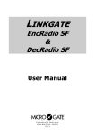
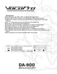
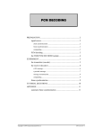
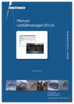
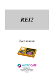
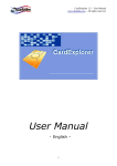
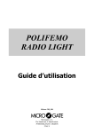
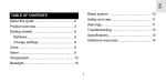
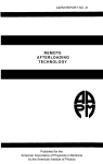
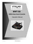
LINKGATE EncRadio & DecRadio User Manual Version 1.0 Microgate S.r.l. Via Stradivari, 4 I - 39100 BOLZANO - ITALY http://www.microgate.it EncRadio & DecRadio User Manual 2 EncRadio & DecRadio User Manual 3 INDEX 1 LINKGATE ENCRADIO & DECRADIO SYSTEM ............................................................. 4 1.1 1.2 1.3 1.4 1.5 E NC R ADIO ........................................................................................................... 5 D EC R ADIO ........................................................................................................... 6 I NTRODUCTION .................................................................................................... 7 F IELD OF USE AND H OMOLOGIZATION .................................................................... 7 L INKGATE E NC R ADIO : 3 SAFETY FEATURES FOR RADIO TRANSMISSION ..................... 8 1.5.1 1.5.2 1.5.3 1.6 1.7 1.8 1.9 1.10 1.11 1.12 1.13 1.14 1.15 1.16 1.17 2 Digital transmission of impulses............................................................................... 8 The Repeat function ................................................................................................ 8 Internal memorization of event times ........................................................................ 8 S WITCHING ON ..................................................................................................... 9 S ELECTING THE CHANNEL ..................................................................................... 9 S ELECTING THE SIGNAL TYPE ................................................................................ 9 I MPULSE TRANSMISSION ..................................................................................... 10 U SING THE R EPEAT FUNCTION ............................................................................. 10 T AKING A SPEED ................................................................................................ 10 R ESETTING THE MEMORY .................................................................................... 11 S YNCHRONIZATION AND A UTOSYNCHRONIZATION ................................................. 12 T RASFERRING DATA TO RACETIME 2.................................................................. 13 M ODEM FUNCTION ............................................................................................. 13 T RANSMISSION FREQUENCY VARIATION ................................................................ 14 M AINTENANCE AND BATTERY RECHARGING .......................................................... 15 APPENDIX ...................................................................................................................... 16 2.1 2.2 2.3 T RANSMISSION PROTOCOL ................................................................................... 17 R ADIO MODULE TECHNICAL DATA SHEET .............................................................. 18 S YSTEM ACCURACY ............................................................................................ 19 EncRadio & DecRadio User Manual 1 LINKGATE ENCRADIO & DECRADIO SYSTEM 4 EncRadio & DecRadio User Manual 5 1.1 EncRadio 5 1 REPEAT SIGNAL 2 SYNC RESET 2ND MODEM 6 11 SERIAL SIGNAL TYPE 3 0= START ON 1-E= LAP F= STOP S CHANNEL L SELECT 9 10 8 4 VISTA FRONT FRONTALE VIEW 1 2 3 4 5 6 7 8 9 10 11 7 VISTA LATERAL LATO SINISTRO VIEW VISTA POSTERIORE BOTTOM VIEW SIGNAL button SECOND FUNCTION button Selector for redundancy of signal transmitted (Long/Short) On/Off switch REPEAT button MODEM button Rotating selector for type of signal transmitted (Start, Lap, Stop) Channel transmission selector LOW BATTERY led Jack connector for battery recharge Cover for access to DIP SWITCH selector for transmission frequency ATTENTION: Starting from 2004 all the shipped DecRadio/EncRadio, will have this dip-switch configuration: OFF OFF OFF ON. In order to use the new DecRadio/EncRadio with the old one, the dip-switches must be made equal on all the devices. Anyway we suggest you to use the OFF OFF OFF ON configuration. EncRadio & DecRadio User Manual 6 5 2 3 1 VISTA LATO INFERIORE BOTTOM VIEW 1 2 3 4 5 6 6 4 VISTA LATO SUPERIORE UPPER VIEW SIGNAL signal banana jack (GREEN) Earth signal banana jack (BLACK) SPEED signal banana jack (RED) 5 pole Nucletron connector for Radio connection and data download BNC for external antenna connection MODEM input banana jack 1.2 DecRadio 2 1 3 1 2 3 BNC for external antenna connection 5 pole Nucletron connector for Radio output Cover for access to DIP SWITCH ATTENTION: Suggested dip-switch configuration: OFF OFF OFF ON EncRadio & DecRadio User Manual 7 1.3 Introduction The transmission of an impulse via radio is a critical phase in timekeeping. The possibility of losing the data transmitted, of having very inaccurate timing and the transmission difficulties in some zones has often made timekeepers and trainers sceptical about this type of approach. The LINKGATE system represents a radical innovation in the field of radio transmission of impulses for timekeeping. Technological evolution has enabled us to go from the old impulse transmission systems to the more modern data transmission concept, which can guarantee extreme accuracy, the transmission of large quantities of information and greater reliability. In addition, the compact size of the system and the possibility of using it with any type of VHF or UHF transmitter radio makes the LINKGATE system the ideal instrument for training and competitions at every level. Linkgate EncRadio and DecRadio represent a further innovation with respect to the well-known and highly esteemed Linkgate Encoder and Decoder. The evolution of the products has resulted in the embedding of high reliability low power radio modules (433 MHz 10 mW: see radio module technical sheet on p.18) for transmission and reception of signals in both the transmitter (Linkgate EncRadio) and receiver (Linkgate DecRadio). Exploiting the characteristics of the modules, which work on FM on a very narrow band, and the intrinsic reliability of Linkgate EncRadio and DecRadio, long distance transmission (over 2 km) can be achieved without the need of external radio transceivers. However, for applications which are critical from this point of view it is always possible to connect any type of VHF or UHF transmitter. In addition, the system’s extremely low power consumption allows long autonomy of use which, together with the possibility of recharging the batteries, represents a great plus of the whole system. 1.4 Field of use and Homologization The device is intended to be used for competitive sports activities (as indicated in Art. 334 of cod. P.T. point 4) in all sports disciplines (e.g. skiing, athletics, horse-racing, mountain bike, motor racing,etc.) both at amateur and professional level. The homologization code is DGPGF/4/2/03/3398837FO/. EncRadio & DecRadio User Manual 8 1.5 Linkgate EncRadio: 3 safety features for radio transmission To overcome unreliability and the various problems associated with the old system of radio transmission of impulses, LINKGATE Encoder offers a number of innovative solutions. 1.5.1 Digital transmission of impulses Linkgate EncRadio transmits sets of data (no longer a single impulse) that contain a vast amount of information. In particular, the following are transmitted: • • • • The transmitter’s Code (which can be selected with the Channel Select switches) The Type of signal transmitted (Start, Lap number or Finish, which can be selected with the Signal Type switch) How long ago the event took place The running Time of a speed base (if present) In addition, the kit contains numerous control codes and error auto-correction codes which prevent a signal from being incorrectly interpreted during reception. All the data (information + control codes) is transmitted 16 times, in order to reduce the possibility of reception failure. Even with very disturbed signal transmission, this system ensures maximum reliability and precision (+/- 0.4 thousandths of a second); in short, you only need the complete reception of a single set of data to be able to reconstruct the original time of the event. 1.5.2 The Repeat function If there are any problems in data reception, (radio malfunction, interference from a more powerful transmission, a cable which comes unplugged, etc...) you can use the REPEAT function. Linkgate EncRadio allows you to repeatedly re-transmit impulses which have not been received, even after a considerable length of time has passed. As soon as the transmission of an event begins, Linkgate EncRadio starts counting the time from the start. By pressing the REPEAT key, you transfer the correct time to the chronometer which takes into account the time which has passed up to that moment. 1.5.3 Internal memorization of event times Linkgate Encoder is equipped with a Real Time Clock that allows you to use event times in event management. This special characteristic allows you to save the times of every event on a permanent memory, then enabling you to download its contents through serial link onto Microgate’s chronometers. The device memorises the last 256 event times and speeds and therefore allows you to retrieve any data lost because of radio malfunction or any other reason. EncRadio & DecRadio User Manual 9 1.6 Switching on To switch the system on/off, EncRadio has an ON/OFF selector (see chap. EncRadio p.5). Switching off and switching on again reset the system and cancel the memory. 1.7 Selecting the channel Every Linkgate Encoder is equipped with a 7 switch panel (CHANNEL SELECT switch from 2 to 8 see chap. EncRadio p. 5) for setting the transmission channel. The transmission channel is used in such a way that only the chronometers Racetime2 and REI2 set to the same channel for reception can recognize the transmission signal as valid. When it is turned on, every Microgate chronometer displays the currently selected channel (both as a number and as an ON/OFF configuration of the Linkgate Encoder switches). By choosing the same switch configuration on the Encoders that you want to use, you can be certain to receive only the signals from your own timing system. This type of filter for signals being received is particularly useful as, by selecting different channels you can use several systems (chronometer + Encoder) in the same zone and even on the same frequency without any risk of timings interfering with one another. 1.8 Selecting the signal type Linkgate Encoder can identify the type of impulse that is being transmitted (Start, Lap number or Finish). The rotary selector (marked SIGNAL TYPE, see chap. EncRadio p. 5) has 16 positions from 0 to F with the following meanings: 0= START 1= LAP n° 1 … 9= LAP n° 9 A= LAP n° 10 B= LAP n° 11 C= LAP n° 12 D= LAP n° 13 E= LAP n° 14 F= STOP The type of signal is chosen by placing the number or letter for the signal you want next to the black dot by the words SIGNAL TYPE. (Note: the letters are written on the edge of the selector). EncRadio & DecRadio User Manual 10 1.9 Impulse transmission An impulse can be transmitted in two ways: 1) with the manual activation key 2) by means of any signal given by the closing of a contact normally open produced by a gate or photocell, using the BLACK banana jack as a ground and the GREEN banana jack as the signal. At the end of data transmission, the Linkgate Encoder will emit a BEEP, which signals that the device has functioned correctly. By using switch #1 (next to the words SHORT IMPULSE LONG) you can set transmission duration (approximately 2.3 seconds for long transmission and 0.6 seconds for short). By choosing long transmission, you will obtain the greatest redundancy of information as the data will be transmitted 16 times. If you select short transmission the set of data will only be transmitted 4 times so you will have lower redundancy but with a substantial reduction of transmission time. For normal use, we advise you to use long transmission (switch #1 OFF) in order to maximize the redundancy of transmitted data. However, for special applications such as the taking of several intermediate times very close together, using short transmission is the only practical solution if transmissions are not to overlap. 1.10 Using the Repeat function If for some reason data was not received by the Microgate chronometers you can retransmit to them by pressing the REPEAT key even after a considerable interval of time. If the problem should continue, the event data can be re-transmitted as many times as necessary until satisfactory reception has been obtained. 1.11 Taking a speed With Linkgate Encoder you can receive up to 16 pass-by speeds from as many different measurement zones. The basic idea is to calculate the speed base time extremely accurately and transmit it together with the corresponding impulse (START, LAP or STOP). Then, by inserting the length of every single speed base into the Micorgate chronometer, you can obtain the value for the average speed for that stretch. The input speed base signal must be brought onto the RED banana jack (see chap. EncRadio p. 5) and the relative ground onto the BLACK banana jack; the output speed base signal must be brought onto the GREEN banana jack together with its ground which must be connected to the BLACK banana jack. When an impulse is received from a speed base input (from the RED banana jack), the LINKGATE Encoder sets the time running. If within 8 seconds there is an impulse from the speed base output (from the GREEN banana jack), the LINKGATE Encoder will transmit the time between the two signals (speed base time) and the impulse of the speed base output (that is, the corresponding LAP or STOP impulse). In the case of a START signal (with the rotating selector on position 0), the impulse of the output signal from the speed base will always be transmitted, but the receiving chronometer will reconstruct the correct time. If more than 8 seconds pass between an input speed base impulse and an output impulse, the system will automatically discard the value – only transmitting the output speed base impulse (the signal corresponding to the GREEN banana jack). EncRadio & DecRadio User Manual 11 BLACK PLUG IN BLACK SOCKET POLIFEMO BLACK PLUG IN BLACK SOCKET DECRADIO ENCRADIO CAB048 or CAB050 GREEN PLUG IN GREEN SOCKET GREEN PLUG IN GREEN SOCKET POLIFEMO GREEN PLUG IN RED SOCKET BLACK PLUG IN BLACK SOCKET BLACK PLUG IN BLACK SOCKET GREEN PLUG IN GREEN SOCKET Figure 1 Figure 1 shows the connections for a speed measurement with the use of 2 Polifemo photocells: the first photocell must be connected (2 meter CAB050 or 20 meter CAB048 cables) to EncRadio’s Red and Black banana jacks and the second to the Green and Black banana jacks. The rotating selector for selection of the signal on EncRadio must be set to LAP E. 1.12 Resetting the memory Resetting the memory causes the deletion of stored data and of the system’s internal time. You can activate reset by keeping the 2ND key pressed down and then releasing the REPEAT (RESET) key. When this command has been received, Linkgate Encoder will emit three tones as follows: BOOP-BEEP-BOOP. The system is reset! EncRadio & DecRadio User Manual 12 1.13 Synchronization and Autosynchronization Linkgate Encoder is equipped with a REAL TIME CLOCK which enables you to relate any event to a time. It is therefore possible to synchronize the Linkgate Coder’s internal clock with any type of chronometer. The procedure for synchronizing the system is as follows: • • • • • • Connect the chronometer’s ground (GND) with the Linkgate Encoder’s BLACK banana jack Hold down the 2ND key and then press and release the SIGNAL (SYNC) key Linkgate Encoder will emit the tones BOOP-BEEP (the system is waiting for a START) Connect the start line to the GREEN banana jack Within two minutes give a start signal to synchronize the system (either by pressing the SIGNAL key or by closing the start line on the ground) On receiving a START signal, Linkgate Encoder will emit two tones tone: BEEP-BOOP (the system is synchronized) If you wish to synchronize two or more Encoders with a chronometer, the procedure remains the same. You must connect all the ground lines (BLACK banana jack) with the chronometer’s ground; then for every Linkgate Encoder you must activate the SYNC procedure (the second point in the procedure), connect the starting line to all the GREEN banana jacks and give a common START. As well as the normal synchronization described above, EncRadio’s internal clock and that of the chronometer can be autosynchronized after transferring any event times memorised by EncRadio (see REI2 or RACETIME2 reference manual for autosynchronization). It is important to remember that autosynchronization can only take place if EncRadio has not been switched off or synchronized in the time between the taking of the event and data download. Keeping in mind the accuracy of the EncRadio oscillator (see chap. System accuracy p.19), if the data memorised on a chronometer is downloaded, it is advisable to use normal synchronization when the time events are taken shortly after the synchronization itself, while it is preferable to use autosynchronization in cases where the event times are taken just before data downloading. EncRadio & DecRadio User Manual 13 1.14 Trasferring data to RACETIME 2 Linkgate Encoder memorises the last 256 events and the last 256 speeds (if received) on an internal permanent memory and so makes possible retrieval after an interval of time of any impulses “lost” as a result of radio malfunction or for any other reason. To be able to download the contents of the Linkgate Encoder’s memory onto the Racetime2 Chronometer, it is necessary to use the appropriate cable, which should be connected to the 5 pole connector of the LINKGATE Encoder at one end, and at the other to the 15 pole connector of Racetime2. Once the correct menu has been selected on Racetime2’s chronometer, you can proceed with data downloading by pressing the 2ND key and then by pressing and releasing the “MODEM” (SERIAL) key. The start of downloading is signalled by the two tones BOOP-BEEP; then within 2 seconds two counters will appear on Racetime2’s display screen to indicate the number of times and speeds actually downloaded. At the end of data downloading, the two tones BEEP-BOOP indicate that the procedure has terminated correctly. NOTE: if you download data immediately after performing a memory RESET (2ND + REPEAT (RESET)) and without transmitting any impulses, LINKGATE Encoder will download the entire contents of the memory (256 times + 256 speeds). 1.15 Modem function Linkgate Encoder can also be used as a modem transmitter. Contrary to what happens when transmission is generated during an event, however, input does not take the form of sets of data with error correction codes, but is simply transformed into a signal compatible for radio transmission. Data reliability is left entirely to the effectiveness of the radio system. In this function mode, Linkgate Encoder accepts a Serial signal for inputs with a maximum speed of 1200 Baud and generates a FSK modulation between 1200 Hz (logic signal 0) and 1800 Hz (logic signal 1). The digital input signal (level RS 232, RS 485 or TTL) is connected to the blue banana jack and the black banana jack (see chap. EncRadio p.5). The MODEM function can be activated by pressing the “MODEM” key 3 times consecutively and rhythmically. At the first two presses, you will hear a BEEP tone. At the third, the tones BOOPBEEP will signal entrance into MODEM function. If the key is not pressed with the correct rhythm, the system will refuse to enter this mode. The reason for this complicated procedure for activating this function is that the MODEM function quickly uses up the battery. In this way you can avoid the danger of rapidly running down the battery by accidentally touching the MODEM key. To terminate the transmission session you need only press the MODEM key once. The system will emit the tones BEEP-BOOP to signal correct termination procedure. EncRadio & DecRadio User Manual 14 1.16 Transmission frequency variation In some cases it will be necessary to vary the transmission frequency of EncRadio/DecRadio (for example when two Linkgate systems are used simultaneously). Obviously the receiver and transmitter will have the same frequency. ON 1 2 3 4 ON 1 2 3 4 Figure 2 As can be seen in Figure 2, the DIP SWITCH for frequency selection is four way, so 16 different frquencies can be set: Frequency set (KHz) Switch 1 Switch 2 Switch 3 Switch 4 433.900 433.950 434.000 434.050 434.100 434.150 434.200 434.250 434.300 434.350 434.400 434.450 434.500 434.550 434.600 434.650 ON OFF ON OFF ON OFF ON OFF ON OFF ON OFF ON OFF ON OFF ON ON OFF OFF ON ON OFF OFF ON ON OFF OFF ON ON OFF OFF ON ON ON ON OFF OFF OFF OFF ON ON ON ON OFF OFF OFF OFF ON ON ON ON ON ON ON ON OFF OFF OFF OFF OFF OFF OFF OFF EncRadio & DecRadio User Manual 15 1.17 Maintenance and battery recharging Linkgate EncRadio and DecRadio have been designed as maintenance-free devices. Under normal operating conditions, the rechargable NiMh batteries embedded in the EncRadio guarantee more than 200 transmission impulses. When the battery is low, then the usual long tone at the end of every transmission is replaced by a three-tone sequence BEEP-BEEP-BEEP. In this case the batteries should be recharged as soon as possible. During recharging, the presence of the external supply is signalled by the battery recharge led situated near the power supply. Recharging ends after about 8 hours and is not signalled by the device. EncRadio & DecRadio User Manual 16 2 APPENDIX EncRadio & DecRadio User Manual 17 2.1 Transmission protocol HEADER Progressive byte N° Description Contents 1 2 3 Lap 0x0F Stop 4 5 6 7 8 9 10 Initial Header Code Linkgate Channel Signal type 0xAA 0..127 Dec 0x00 Start 0x01..0x0E Transmission start time (in 1/32768 di sec) Time_LL Time_LH Time_HL Time_HH 0x77 0xBA 0x31 Internal Code Internal Code Internal Code DATA FRAME Consecutive byte no. Description Contents 11 12 13 14 15 16 Initial frame code Chronological impulse (in 1/32768 di sec) 0xAA Time_LL Time_LH Time_HL Time_HH Speed_Low 17 Speed value in 1/8192 of a second Speed_High EncRadio & DecRadio User Manual 18 2.2 Radio module technical data sheet For module data transmission, EncRadio and DecRadio use UHF FM narrow band on the free frequency 434 MHz. Both the transmitter and receiver are fitted with a microprocessor-controlled frequency synthesizer. The frequency ranges from 433.875 MHz to 434.650 MHz on 32 channels which can be selected with a 5 bit dip-switch on the module. Specifications common to the TX and RX radio modules Form of communication Monodirectional TX → RX Oscillator PLL controlled VCO Frequency From 433.875 MHz to 434.650 MHz Number of channels 32 Frequency step between channels 25 KHz Frequency stability ± 2.5 KHz (-10 to 5 °C) Frequency reply From 10 Hz to 2.4 KHz Baud Rate From 300 to 4800 bps Operational temperature From -10 to +60 °C TX transmitter specifications Transmitter type Output power Start-up time Modulation Input levels Input signal type Deviation Spurious emissions Power on adjacent channel Power supply Power supply current PLL synthesizer 10mW +0/-3 dB to 50 Ohm 60ms Narrow band FM From 3 V to 12 V Digital 2 KHz < 60 dBm < 200 nW From 3 V to 12 V 30 mA RX receiver specifications Receiver type Sensitivity Selectivity Demodulation Distortion Signal/Noise ratio Output type Power supply Power supply current Double superheterodyne PLL synthesizer -120 dBm (12dB / SINAD, CCITT filter) ± 7.5 KHz to -6dB Narrow band FM < 5% to 1 KHz 35 dB Digital Open Collector From 3.6 V to 12V 30 mA EncRadio & DecRadio User Manual 19 2.3 System accuracy When time events are downloaded from EncRadio slight inaccuracies in the times of time events are possible due to the accuracy of EncRadio’s internal oscillator. The maximum error possible is equal to ±10 PPM (parts per million) in a temperature range of -20 to +40 °C (that is, ±0.8 secondi ogni 24 ore).