1
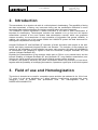
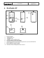
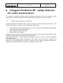
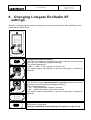
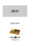
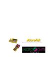
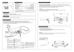
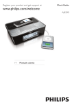
LINKGATE
EncRadio SF
&
DecRadio SF
User Manual
Microgate s.r.l.
Via Stradivari, 4 Stradivaristr.
39100 BOLZANO - BOZEN
ITALY
LINKGATE EncRadio SF & DecRadio SF
User Manual
Doc: ENC_SF_R_200_000
Version: 2.0
Page 2 of 12
LINKGATE EncRadio SF & DecRadio SF
User Manual
Doc: ENC_SF_R_200_000
Version: 2.0
Page 3 of 12
1. Index
1.
INDEX ....................................................................................................................................................... 3
2.
INTRODUCTION...................................................................................................................................... 4
3.
FIELD OF USE AND HOMOLOGIZATION........................................................................................... 4
4.
ENCRADIO SF.......................................................................................................................................... 5
5.
DECRADIO SF.......................................................................................................................................... 6
6.
LINKGATE ENCRADIO SF: SAFETY FEATURES FOR RADIO TRANSMISSION ......................... 7
6.1.
D IGITAL TRANSMISSION OF IMPULSES .................................................................... 7
7.
SWITCHING ON....................................................................................................................................... 8
8.
CHANGING LINKGATE ENCRADIO SF SETTINGS .......................................................................... 9
9.
IMPULSE TRANSMISSION .................................................................................................................. 10
10.
SETTING THE BIB NUMBER............................................................................................................. 10
11.
MAINTENANCE AND BATTERY RECHARGING .......................................................................... 10
11.1.
11.2.
11.3.
11.4.
B ATTERY MAINTENANCE .................................................................................... 10
LOW BATTERY WARNING ................................................................................ 10
B ATTERY RECHARGE ......................................................................................... 10
B ATTERY CHARGE INDICATOR ............................................................................ 10
12.
LINKGATE ENCRADIO SF TECHNICAL DATA............................................................................. 11
13.
LINKGATE DECRADIO SF TECHNICAL DATA............................................................................. 11
LINKGATE EncRadio SF & DecRadio SF
User Manual
Doc: ENC_SF_R_200_000
Version: 2.0
Page 4 of 12
2. Introduction
The transmission of an impulse via radio is a critical phase in timekeeping. The possibility of losing
the data transmitted, of having very inaccurate timing and the transmission difficulties in some
zones has often made timekeepers and trainers sceptical about this type of approach.
The LINKGATE system represents a radical innovation in the field of radio transmission of
impulses for timekeeping. Technological evolution has enabled us to go from the old impulse
transmission systems to the more modern data transmission concept, which can guarantee
extreme accuracy, the transmission of large quantities of information and greater reliability. In
addition, the compact size of the system makes the LINKGATE system the ideal instrument for
training and competitions at every level.
Linkgate EncRadio SF and DecRadio SF represent a further innovation with respect to the wellknown and highly esteemed Linkgate Encoder and Decoder. The evolution of the products has
resulted in the embedding of high reliability low power radio modules (433 MHz 10 mW/500mW)
for transmission and reception of signals in both the transmitter (Linkgate EncRadio SF) and
receiver (Linkgate DecRadio SF).
Exploiting the characteristics of the modules, which work on FM on a very narrow band, and the
intrinsic reliability of Linkgate EncRadio SF and DecRadio SF, long distance transmission (over
2Km for the 10mW version and over 9Km for the 500mW version) can be achieved.
In addition, the system’s extremely low power consumption allows long autonomy of use which,
together with the possibility of recharging the batteries, represents a great plus of the whole system.
3. Field of use and Homologization
The device is intended to be used for competitive sports activities (as indicated in Art. 334 of cod.
P.T. point 4) in all sports disciplines (e.g. skiing, athletics, horse-racing, mountain bike, motor
racing,etc.) both at amateur and professional level. The homologization code is
DGPGF/4/2/03/3398837FO/.
LINKGATE EncRadio SF & DecRadio SF
User Manual
Doc: ENC_SF_R_200_000
Version: 2.0
Page 5 of 12
4. EncRadio SF
7
1
3
2
6
5
4
FRONT VIEW
LEFT SIDE VIEW
BACK VIEW
9
10
8
BOTTOM VIEW
VISTA LATO SUPERIORE
Figure 1
1
2
3
4
5
6
7
8
9
10
Numerical display
< Down arrow > key
< Up arrow > key
< ON/OFF > key for switching on/off
Led di segnalazione ricarica accumulatori
Connettore Jack per ricarica accumulatori
Coperchio per accesso al connettore di programmazione (riservato MICROGATE)
Boccola VERDE per ingresso segnali
Boccola NERA per segnale di Massa
Connettore TNC per collegamento antenna esterna
LINKGATE EncRadio SF & DecRadio SF
User Manual
Doc: ENC_SF_R_200_000
Version: 2.0
Page 6 of 12
5. DecRadio SF
2
1
Figure 2
1
2
TNC for external antenna connection
5 pole Nucletron connector for Radio output
LINKGATE EncRadio SF & DecRadio SF
User Manual
Doc: ENC_SF_R_200_000
Version: 2.0
Page 7 of 12
6. Linkgate EncRadio SF: safety features
for radio transmission
To overcome unreliability and the various problems associated with the old system of radio
transmission of impulses, LINKGATE Encoder SF offers a number of innovative solutions:
6.1.
Digital transmission of impulses
Linkgate EncRadio SF transmits sets of data (no longer a single impulse) that contain a vast
amount of information. In particular, the following are transmitted:
•
•
•
•
The transmitter’s Code (software selection from 127 channels and redundancy length data)
Bib number (selectable with software)
How long ago the event took place
Battery Status (Low Battery)
In addition, the kit contains numerous control codes and error auto-correction codes which prevent
a signal from being incorrectly interpreted during reception.
All the data (information + control codes) is transmitted 16 times, in order to reduce the possibility
of reception failure.
Even with very disturbed signal transmission, this system ensures maximum reliability and
precision (+/- 0.4 thousandths of a second); in short, you only need the complete reception of a
single set of data to be able to reconstruct the original time of the event.
LINKGATE EncRadio SF & DecRadio SF
User Manual
Doc: ENC_SF_R_200_000
Version: 2.0
Page 8 of 12
7. Switching on
Pressing the ON/OFF key switches on the system.
The current EncRadio settings are shown:
)
Check that the EncRadio transmission channel is
the same as the channel set on the chronometer.
1
Current setting of transmission channel (CHANNEL):
2
3
The transmission channel is used to make sure that only Racetime2 or
REI2 chronometers with the same reception channel setting can receive
the transmitted signal as valid. Every Microgate chronometer allows you
to view the channel currently selected. By selecting the same number on
the EncRadio SF that you wish to use, you will be certain of receiving
only the signals from your own timing system. This type of filtering of the
signals received is particularly useful as, by selecting different channels,
it is possible to use a number of systems (chronometer + EncRadio SF)
in the same zone and also on the same radio frequency without the risk
of the chronometers interfering with each other.
Current setting of signal redundancy:
4
5
6
With the setting of signal redundancy, transmission duration can be
defined (about 2.3 seconds for long transmission <-L-> and 0.6 seconds
for short <-S->). Selecting long transmission results in greater
information redundancy as the same data are transmitted 16 times. If
short transmission is selected the set of information is transmitted only 4
times resulting in lower redundancy but considerably reducing
transmission length.
For normal use we recommend you always use long transmission ( <-L> ) to maximise redundancy of the data sent. However for particular
applications, such as taking a number of intermediate times very close
together, the use of short transmission is the only feasible solution to
prevent a number of transmissions overlapping one another.
Long < BEEP >
Bib number 0 is displayed
View for settings terminated and system ready for use
At the end of viewing Linkgate EncRadio emits a beep to signal that the system is ready for use.
To switch off the system press the ON/OFF key for about 1 second until the word “OFF” appears.
Releasing the ON/OFF key switches off the system.
Switching off and switching back on reset the system and delete the memory.
LINKGATE EncRadio SF & DecRadio SF
User Manual
Doc: ENC_SF_R_200_000
Version: 2.0
Page 9 of 12
8. Changing Linkgate EncRadio SF
settings
Changes in settings can be made by keeping an arrow key pressed down while switching on the
device with the ON/OFF key.
1
2
Changing transmission channel:
The user can change the transmission channel with the two arrow keys
when the current setting is displayed (blinking).
The possible settings are:
< 000 > - < 127 > = From channel 0 to channel 127
The system passes automatically to the next setting after 4 seconds of
inactivity.
3
4
Changing data transmission redundancy:
The user can change data transmission redundancy with the two arrow
keys when the current setting is displayed (blinking).
The possible settings are:
< -L- > = Long transmission of about 4 seconds
< -S- > = Short transmission of about 0.6 seconds
The system passes automatically to the next setting after 4 seconds of
inactivity.
5
6
Long < BEEP >
Bib number 0 is displayed
Settings modification is terminated and the system is ready for use.
LINKGATE EncRadio SF & DecRadio SF
User Manual
Doc: ENC_SF_R_200_000
Version: 2.0
Page 10 of 12
9. Impulse transmission
An impulse can be transmitted by means of any signal given by the closing of a contact normally
open produced by a gate or photocell, using the BLACK banana jack as a ground and the GREEN
banana jack as the signal.
At the end of data transmission, the Linkgate EncRadio SF will emit a BEEP.
10. Setting the bib number
The two arrow keys can be used to set a bib number. In this way the chronometer can
automatically relate an event received from EncRadio.
The function is disabled if the bib number 0 is set.
After transmission of an impulse the bib number automatically moves up.
11. Maintenance and battery recharging
11.1.
Battery maintenance
The system is designed to eliminate the need for any kind of ordinary maintenance and in
conditions of normal use the rechargeable batteries allow an autonomy of about 5000
transmissions for EncRadio SF and about 2000 transmissions for EncRadio SF 500.
11.2.
LOW BATTERY warning
When the remaining time of Linkgate EncRadio’s autonomy is limited, it warns the user with a
visual and sound signal. The low battery warning is made with the emission of three short tones
BEEP-BEEP-BEEP (and the indication < Lo > on the display) at the end of the transmission of an
impulse.
Low battery status is also indicated with a blinking red Led located close to the recharge connector.
When an event is transmitted, the Racetime 2 or Rei 2 chronometers also receive the battery
status and warn that EncRadio’s autonomy is limited.
When this happens the battery should be recharged as soon as possible.
11.3.
Battery recharge
The presence of the recharge current is signalled when the Led located close to the recharge
connector is on. This Led also indicates if battery recharge is in progress (orange Led) or if it has
finished (green Led).
The time needed for recharging depends on the current charge status of the battery.
When recharging is over, the battery status Led stays on and is continuous green.
Recharging finishes after about 1.5 hours if the battery is completely empty.
11.4.
Battery charge indicator
When the ON/OFF key is pressed, the percentage of charge remaining in the battery is displayed.
LINKGATE EncRadio SF & DecRadio SF
User Manual
Doc: ENC_SF_R_200_000
Version: 2.0
Page 11 of 12
12. Linkgate EncRadio SF technical data
Weight
Size
Operating temperature
Frequency
Type of transmitter
Transmission mode
Form of communication
Number of channels
Radio transmission power
Impulse transmission accuracy
Time base
Supply:
Battery
Recharge
Battery recharge
Autonomy
Processor
Keyboard and controls
Connections
Radio transmission range in normal
conditions
145g
100 x 50 x 40 mm (l x h x p)
–25º/+70ºC
434.075 MHz
PLL Synthesizer
Digital FSK transmission; redundancy code with information accuracy check
and autocorrection
TX monodirectional
1
EncRadio SF :
10mW
EncRadio SF 500 :
500mW
± 0.4 ms
Quartz 4.194304 MHz ±5ppm from –25º/+70ºC
Rechargeable Lithium-Ion 3.7V 500mAh
8V÷20VDC 300mA
Built-in “smart” recharger
EncRadio SF:
Over 5000 events
EncRadio SF 500 :
Over 2000 events
Remaining charge indicator
Visual and sound signalling of “Low Battery” status
8 bit C-MOS microprocessor
•
Signal and Repeat keys, 2 arrow and second function keys
•
ON/OFF key
•
Software selection of long/short signal
•
Software selection of transmission channel
•
Auxiliary input on Ø 4mm socket for taking speeds (contact normally
open)
EncRadio SF :
Over 2 Km
EncRadio SF 500 :
Over 9 Km
13. Linkgate DecRadio SF technical data
Weight
Size
Operating temperature
Frequency
Type of receiver
Reception mode
Form of communication
Number of channels
Power supply
Connections
110g
90 x 50 x 25 mm (l x h x p)
–25º/+70ºC
434.075 MHz
Double Superheterodyne, PLL Controlled Fixed channel
FSK decoding
RX monodirectional
1
5 VDC, supplied directly from chronometer
Cable with 5 pole connector for connection to chronometer
LINKGATE EncRadio SF & DecRadio SF
User Manual
Doc: ENC_SF_R_200_000
Version: 2.0
Page 12 of 12
Copyright
Copyright © 1999, 2005 by Microgate s.r.l.
All rights reserved
No part of this document or of any of the individual manuals may be copied or reproduced without
previously making a written application to Microgate s.r.l. for authorisation.
All the marks or names of products mentioned in this document or in the individual manuals are or
may be registered marks belonging to the individual firms.
Microgate, REI2, REI, RaceTime, MicroTab, µTab, MicroGraph, µGraph, MicroBeep, µBeep,
Uploder, Microrun, µFlasher, LinkPod, LinkGate, LinkGate encoder, LinkGate decoder, EncRadio,
DecRadio, Polifemo, MicroSem, µSem, are registered marks of Microgate s.r.l. or of licensed users.
Microgate s.r.l. reserves the right to modify the products described in this document and/or in the
relative manuals without notice.
The manuals are available in the following languages: Italian, English, German and French.
Microgate S.r.L
39100 Bolzano - Bozen
Via Stradivari 4 Stradivaristr.
ITALY
Tel. +39 471 501532 - Fax +39 471 501524
e-mail [email protected]