1
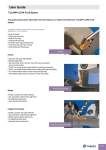
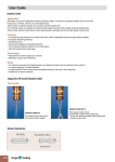
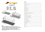
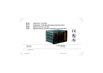
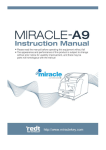
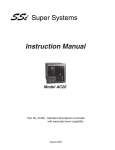
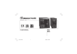
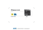
User’s Manual
Portable Chamfering Machine
#535, Migun Techno World II
187 Techno 2-Ro, Yuseong-Gu, Daejeon, 305-500, S.Korea
Tel : +82-10-5380-5270 / Web : www.ahaind.com
E-mail : [email protected]
Contents
● Specifications ・・・・・・・・・・・・・・・・・・・・・・・
3
● Cautions ・・・・・・・・・・・・・・・・・・・・・・・・・
3
● Chamfering Depth Adjustment ・・・・・・・・・・・・・・・・
4
● Chamfering Angle Adjustment ・・・・・・・・・・・・・・・・
4
● Work Procedures ・・・・・・・・・・・・・・・・・・・・・
4
● Example : Characteristics of Chamfering Depth by Angle ・・・・
6
● Troubleshooting ・・・・・・・・・・・・・・・・・・・・・・
7
● Use of Roller Guide ・・・・・・・・・・・・・・・・・・・・
7
● Standard Accessory ・・・・・・・・・・・・・・・・・・・・
8
● Converting from Model-2100 to Model-1000 ・・・・・・・・・・
9
● Insert Tips for Model-1000 ・・・・・・・・・・・・・・・・・・
9
● Speed Controller ・・・・・・・・・・・・・・・・・・・・・・
10
● Roller Plate ・・・・・・・・・・・・・・・・・・・・・・・・
11
● EC Declaration of Conformity ・・・・・・・・・・・・・・・・
12
● Warranty ・・・・・・・・・・・・・・・・・・・・・・・・・
13
● Chamfer-Mill 1000 Part List / Drawing ・・・・・・・・・・・・
14
● Chamfer-Mill 2100 Part List / Drawing ・・・・・・・・・・・・
15
● METABO W24-230 Drawing ・・・・・・・・・・・・・・・・・
16
Chamfer-Mill User’s Manual
● Model-1000
● Model-2100
Specifications
Specifications
Model - 1000
Model - 2100
Minimum Thickness of Steel Plate
3mm
3mm
Minimum Chamfering Width
0mm
0mm
Maximum Chamfering Width (B)
10mm
21mm
Maximum Chamfering Thickness (45°) (A)
7mm
15mm
Adjustment Angle
15∼60°
15 ~ 60°
V-Block Length
224mm
224mm
5 EA
10 EA
Number of Inserts
Motor Specifications
Single phase 230V, 50/60Hz, 2400W
Weight
10.4kg
10.6kg
<<< Patent No. : 10-0952191 >>>
Cautions
1. Always wear safety goggles and ear protection during operation.
2. Keep your hands away from the cutter (List No.6).
3. Do not operate the mill near combustibles as the spattering hot particles may
cause fire.
4. Power supply should be made in accordance with your local rules.
5. To process a new material, start with the chamfering thickness set to minimum
and increase it gradually.
6. Turn on the motor first before approaching the processed material, and also turn off
the motor away from the processed material.
7. Use “20 degree insert tips” only.
Chamfer Mill User’s Manual
-3-
http://www.ahaind.com / AHA Industrial Co.
Chamfering Depth Adjustment
1. Loosen or tighten the upside adjustment knob (List No. 16) watching the scale on the
right side of the frame.
2. A turn of the adjustment knob changes the chamfering depth by 1.25mm. And, as a
turn consists of 8 clicks, each click of the adjustment knob increases or decreases
the chamfering depth by about 0.16mm.
3. The upside chamfering depth adjustment knob can be turned stiffly or smoothly by
adjusting the ball plunger (List No. 20).
Chamfering Angle Adjustment
1. Turn the V-block(List No. 28 & 30) by loosening 4 hexagonal cap screws(List No. 27).
2. Adjust the chamfering angle by watching the scale on the left side.
3. Tighten 4 hexagonal cap screws again. (Check whether the chamfering angle is
accurate by measuring the test chamfered surface with a goniometer.)
Work Procedures
1. Wear safety goggles and ear protection.
2. Hold the D-Handle (List No. 15) with the right hand and the motor switch handle with
the left hand.
3. The motor switch handle is designed to turn at an angle of 90 degrees for convenience.
Push the button in its groove turns right and left at 90 degrees up to 270 degrees.
4. To adjust the height of the motor switch handle held with the left hand, loosen the
locking bolt (List No. 13) and, after adjustment of the height, tighten it again.
5. The motor switch is designed for adjustment in 2 steps for safety. Push and forward
red button to lock the motor switch for continuous mode.
To turn OFF the motor, push and release the switch lever (lower black switch)
6. Always start the motor first before approaching the workpiece, and chamfer the
workpiece left to right.
7. Do not move the chamfer mill backwards, always move it forwards.
Chamfer Mill User’s Manual
-4-
http://www.ahaind.com / AHA Industrial Co.
8. Always start chamfering at the end of the workpiece. If the middle of the workpiece is
to be chamfered first, contact the chamfer mill slowly to the workpiece to prevent
damage of the inserts.
9. Chamfering speed depends on chamfering depth and angle. Chamfering speed can
be adjusted depending on volume of the workpiece, but pay attention not to use the
chamfer mill excessively.
10. Replace the worn and dull inserts with new one as soon as possible, or it may
damage the cutter head.
11. Only 20 degree insert tips should be used.
12. For loosening or tightening the insert for replacement, the 3mm hexagonal T-handle
wrench is used.
13. If the screw (List No. 8) is not easily loosened in replacing the insert tip, do not turn it
by constraint, but loosen the bolt (List No. 13) to remove the whole frame (List No.21),
after loosening the Jam Nut (List No. 11) and separating the Cutter (List No. 6), and then
strike the insert tip with an impact driver to remove it. This makes it easy to loosen the
screw and replace the insert tip.
14. Assemble the parts of List No. 8, 9 and 10 with the M3 hexagonal T-handle wrench as
illustrated below. At this time, turn the insert set screw continuously clockwise so that the
right-hand screw of the cutter body is assembled together with the left-hand screw of the
wedge. To ensure correct assembly of the insert, adjust the insertion depth of the right
-hand screw or left-hand screw so that the head of the insert set screw is placed below
the upper surface of the wedge.
In the Model-1000, set the insert to the center of the cutter wedge.
In the Model-2100, set the insert to the center of the two facing cutters.
Chamfer Mill User’s Manual
-5-
http://www.ahaind.com / AHA Industrial Co.
15. Each insert tip has 4 cutting edges, the insert can be used by rotate each edge.
16. The insert set screw (List No. 8) is the KORLOY’s DHA-0617.
17. The insert tip (List No. 10), we use the products of Kyocera Precision Korea’s products.
This product is coated with titanium and the part numbers are as below :
Part No. : PP9130 SECN 120308-AHA-IC
The wearing rate of the insert depends on the material to be chamfered.
* Note: In case the chamfering width is not large(less than 5C), the following insert tips also
can be used only for Model-1000:
- KORLOY : PC9530 SEKR1203AFSN-MX
- TaeguTec : TT8020 SEKN1203AFTN-EM
- Kyocera : PR730 SEKN1203AFTN
18. If the thickness of the workpiece is less than 5mm, it is recommended to place 8 metal
shims or washers between the V-block plate (List No. 28 and 30) and the V-block end
cap (List No. 26) so that the distance between V-block end caps may get short.
(16 Washers Included)
19. Use of cutting oil (tapping oil, vegetable oil, etc.) ensures improvement of chamfering
speed and longer life of the insert tip. And, if the gas cut plate is to be chamfered, it
ensures lower wear of the insert tip to grind the cut surface (hardened area) before.
Example : Characteristics of Chamfering Depth by Angle
Chamfering depth is characterized as below by chamfering angle (Model-2100):
[Chamfering angle 45°]
[Chamfering angle 30°]
[Chamfering angle 15°]
A: Maximum chamfering depth at the adjusted angle
B: Maximum chamfering width at the adjusted angle
Chamfer Mill User’s Manual
-6-
http://www.ahaind.com / AHA Industrial Co.
Troubleshooting
Troubles
Causes
Solutions
Particles spattering
- High moving speed
- High workpiece hardness
- Lower moving speed.
Chamfered surface is not
smooth
- Dull insert
- Too high moving speed
- Replace insert.
- Lower moving speed.
Longer sparks at motor
carbon brushes
- Deteriorated motor
- Replace or repair motor
parts.
Use of Roller Guide
1. The roller guide (List No. 32) is provided for chamfering round plate or pipe whose
diameter is larger than 6 inch (150mm).
2. For use for the work-piece such as round plate or erected pipe, the roller guide (List
No. 32) is mounted on the large plate (List No. 30) in the state of V-block (List No. 28
& 30) as delivered. For use for the laid pipe, the large plate (List No. 30) and small
plate (List No. 28) are crossed at the end cap (List No. 26) and the roller guide (List
No. 32) is mounted on the large plate (List No. 30).
3. Adjust the chamfering depth to the minimum.
4. Place two rollers at proper positions. <Adjust position of each roller guide (List No.32)
inserted in the groove of the large plate (List No. 30) depending on diameter.>
5. Adjust position of the roller guide (List No. 32) so that the chamfer mill can be easily
put to and away the workpiece.
6. Test work – Increase the chamfering depth little by little.
7. Begin with low speed to prevent damage of the insert.
8. If the workpiece is a long pipe, put the chamfer mill on the pipe and turn the pipe.
Chamfer Mill User’s Manual
-7-
http://www.ahaind.com / AHA Industrial Co.
9. Depending on pipe diameter, the roller guide(ListNo.32) is placed as below:
Standard Accessory
1. 3mm Hexagonal T-handle Wrench - 1ea
2. 4mm Ball L-Wrench - Longitudinal - 1ea
3. 13mm Spanner Combination Wrench - 1ea
Chamfer Mill User’s Manual
-8-
http://www.ahaind.com / AHA Industrial Co.
Converting from Model-2100 to Model-1000
1. Purpose
When chamfering thin steel below 7mm, converting is recommended for saving inserts
and operation time since Model-2100 requires 10 inserts and Model-1000 requires
5 inserts.
2. The Difference of Model-1000 and Model-2100
The difference between Model-1000 and Model-2100 is the numbers of cutter head 1 to 2.
Other specifications are the same for both model.
3. How to Convert
* Please refer to drawings of Model-2100
1) Loosen the bolt(List No.13) and remove frame(List No. 21)
2) disassemble List No.12, 11, 6, 7, 6 in sequence
* Please refer to drawing of Model-1000
3) Assemble Shim(slim)(List No.7-1)
4) Assemble List No.6 and No. 7-2(thick)
5) Assemble List No. 11, 12, 21, 13 in sequence
* List No. 7-1 and 7-2 should NOT be changed
Chamfer Mill User’s Manual
-9-
http://www.ahaind.com / AHA Industrial Co.
Speed Controller
1. Purpose
The motor (W24-230) has 6600RPM(without work load),
4600RPM with work load. This RPM can be used for
steel material, but high RPM to stainless steel can lead
to higher rate of inserts wear.
The speed controller is for protecting the inserts from
higher wearing rate by reducing its RPM
for stainless steel purpose.
2. How to Use
1) Plug speed controller to power outlet and then plug Chamfer-Mill power cable
to the speed controller.
2) When chamfering stainless steel, adjust the controller to 40% ~ 60% according to
chamfering amount workload.
3) Higher % is fast chamfering speed and high insert wearing rate.
Lower % is slow chamfering speed and low insert wearing rate.
Too low RPM % speed may cause vibration.
4) Higher tensile strength (SUS 304, SUS 310, SUS 316, etc) of the materials,
it shows higher insert wearing rate.
Chamfer Mill User’s Manual
- 10 -
http://www.ahaind.com / AHA Industrial Co.
Roller Plate
1. Purpose
Depends on the surface conditions of the workpiece, smoothness and rust, etc,
the friction between the V-Block (List No. 30) and the workpiece can cause
problems, reducing the workability for the operator and increasing
processing time.
By replacing the pre-installed V-Block(List No.30)
with the optional part, Roller Plate, the decreased
friction will increase workability and processing time.
2. The Difference of the standard V-Block and Roller Plate
The length of the standard V-Block is 224mm, this means the minimum length of the
workpiece should be longer than 112mm to chamfer.
However, the workpiece should be longer than 264mm due the the same length of the
Roller Plate or its contact points. Otherwise, the chamfering values will be unstable.
To get constant chamfering value with Roller Plate, place two extension plates (at least
140mm) at the both starting point and end point of the workpiece. (see below)
Chamfer Mill User’s Manual
- 11 -
http://www.ahaind.com / AHA Industrial Co.
EC Declaration of Conformity
Chamfer Mill User’s Manual
- 12 -
http://www.ahaind.com / AHA Industrial Co.
Warranty
1. The manufacturer grants a warranty of 1 year from the date of purchase.
(proven by invoice or delivery note).
2. Excluded from any warranty claims are wear parts, overloading, an improper use,
damage by use of force, as well as any unauthorized modification by user.
3. This warranty is only valid with the carrying out of the instructions of the User's Manual
and correct purpose of use.
4. If the product is or becomes defective as a result of the workmanship in the production or
as a result of a defect in the material, then the manufacturer will replace the part or repair.
Chamfer Mill User’s Manual
- 13 -
http://www.ahaind.com / AHA Industrial Co.
Chamfer Mill User’s Manual
- 14 -
http://www.ahaind.com / AHA Industrial Co.
Chamfer-Mill
Chamfer
Mill User’s 사용설명서
Manual
- 15- 15
- -
아하산업 / http://www.ahaind.com
http://www.ahaind.com
/ AHA Industrial Co.
METABO W24-230
Chamfer Mill User’s Manual
- 16 -
http://www.ahaind.com / AHA Industrial Co.