1
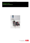
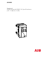
ACS355
Supplement
ACS355 drives with IP66/67 / UL Type 4X enclosure
(0.37…7.5 kW, 0.5…10 HP)
ACS355 drive manuals
DRIVE MANUALS
ACS355 drives (0.37...22 kW, 0.5...30 HP) user’s manual
3AUA0000066143 (EN)
OPTION MANUALS (delivered with optional equipment)
FCAN-01 CANopen Adapter Module user’s manual
3AFE68615500 (EN)
FDNA-01 DeviceNet Adapter Module user’s manual
3AFE68573360 (EN)
FMBA-01 Modbus Adapter Module user’s manual
3AFE68586704 (EN)
FPBA-01 PROFIBUS DP Adapter Module user’s manual
3AFE68573271 (EN)
FRSA-00 RS-485 Adapter Board user’s manual
3AFE68640300 (EN)
MFDT-01 FlashDrop user’s manual
3AFE68591074 (EN)
MAINTENANCE MANUALS
Guide for capacitor reforming in ACS50/150/350/355/550
3AFE68735190 (EN)
ACS355 drives with
IP66/67 / UL Type 4X enclosure
0.37…7.5 kW
0.5…10 HP
Supplement
3AUA0000066066 REV A
EN
EFFECTIVE: 2010-01-01
© 2010 ABB Oy. All Rights Reserved.
5
Safety
What this chapter contains
The chapter contains the safety instructions which you must follow when installing,
operating and servicing the drive. If ignored, physical injury or death may follow, or
damage may occur to the drive, motor or driven equipment. Read the safety
instructions before you work on the drive.
Use of warning symbols
There are two types of safety warnings throughout this manual:
Danger; electricity warns of high voltage which can cause physical
injury and/or damage to the equipment.
General danger warns about conditions, other than those caused by
electricity, which can result in physical injury and/or damage to the
equipment.
Safety
6
Installation and maintenance work
These warnings are intended for all who work on the drive, motor cable or motor.
WARNING! Ignoring the following instructions can cause physical injury or death, or
damage to the equipment.
Only qualified electricians are allowed to install and maintain the drive!
• Never work on the drive, motor cable or motor when input power is applied. After
disconnecting the input power, always wait for 5 minutes to let the intermediate
circuit capacitors discharge before you start working on the drive, motor or motor
cable.
Always ensure by measuring with a multimeter (impedance at least 1 Mohm) that:
1. There is no voltage between the drive input phases U1, V1 and W1 and the
ground.
2. There is no voltage between terminals BRK+ and BRK- and the ground.
• Do not work on the control cables when power is applied to the drive or to the
external control circuits. Externally supplied control circuits may carry dangerous
voltage even when the input power of the drive is switched off.
• Do not make any insulation or voltage withstand tests on the drive.
• If a drive whose EMC filter is not disconnected is installed on an IT system [an
ungrounded power system or a high resistance-grounded (over 30 ohms) power
system], the system will be connected to earth potential through the EMC filter
capacitors of the drive. This may cause danger or damage the drive.
• If a drive whose EMC filter is not disconnected is installed on a corner grounded
TN system, the drive will be damaged.
Note:
• Even when the motor is stopped, dangerous voltage is present at the power
circuit terminals U1, V1, W1 and U2, V2, W2 and BRK+ and BRK-.
WARNING! Ignoring the following instructions can cause physical injury or death, or
damage to the equipment.
• Do not install anything inside the drive that is not explicitly instructed in this
manual or the ACS355 user’s manual.
• The drive is not field repairable. Never attempt to repair a malfunctioning drive;
contact your local ABB representative or Authorized Service Center for
replacement.
• Make sure that dust from drilling does not enter the drive during the installation.
Electrically conductive dust inside the drive may cause damage or lead to
malfunction.
• Ensure sufficient cooling.
Safety
7
Operation and start-up
These warnings are intended for all who plan the operation, start up or operate the
drive.
WARNING! Ignoring the following instructions can cause physical injury or death, or
damage to the equipment.
• Before adjusting the drive and putting it into service, make sure that the motor
and all driven equipment are suitable for operation throughout the speed range
provided by the drive. The drive can be adjusted to operate the motor at speeds
above and below the speed provided by connecting the motor directly to the
power line.
• Do not activate automatic fault reset functions if dangerous situations can occur.
When activated, these functions will reset the drive and resume operation after a
fault.
• Do not control the motor with an AC contactor or disconnecting device
(disconnecting means); use instead the control panel start and stop keys
and
or external commands (I/O or fieldbus). The maximum allowed number
of charging cycles of the DC capacitors (i.e. power-ups by applying power) is two
per minute and the maximum total number of chargings is 15 000.
Note:
• If an external source for start command is selected and it is ON, the drive will start
immediately after an input voltage break or fault reset unless the drive is
configured for 3-wire (a pulse) start/stop.
• When the control location is not set to local (LOC not shown on the display), the
stop key on the control panel will not stop the drive. To stop the drive using the
control panel, press the LOC/REM key LOC
.
REM and then the stop key
Safety
8
Safety
9
Table of contents
ACS355 drive manuals . . . . . . . . . . . . . . . . . . . . . . . . . . . . . . . . . . . . . . . . . . . . . . . . . . . . . . . . . . . 2
Safety
What this chapter contains . . . . . . . . . . . . . . . . . . . . . . . . . . . . . . . . . . . . . . . . . . . . . . . . . . . . . . . .
Use of warning symbols . . . . . . . . . . . . . . . . . . . . . . . . . . . . . . . . . . . . . . . . . . . . . . . . . . . . . . . . . .
Installation and maintenance work . . . . . . . . . . . . . . . . . . . . . . . . . . . . . . . . . . . . . . . . . . . . . . . . . .
Operation and start-up . . . . . . . . . . . . . . . . . . . . . . . . . . . . . . . . . . . . . . . . . . . . . . . . . . . . . . . . . . .
5
5
6
7
Table of contents
About the manual
What this chapter contains . . . . . . . . . . . . . . . . . . . . . . . . . . . . . . . . . . . . . . . . . . . . . . . . . . . . . . .
Scope . . . . . . . . . . . . . . . . . . . . . . . . . . . . . . . . . . . . . . . . . . . . . . . . . . . . . . . . . . . . . . . . . . . . . . .
Compatibility . . . . . . . . . . . . . . . . . . . . . . . . . . . . . . . . . . . . . . . . . . . . . . . . . . . . . . . . . . . . . . . . . .
Intended audience . . . . . . . . . . . . . . . . . . . . . . . . . . . . . . . . . . . . . . . . . . . . . . . . . . . . . . . . . . . . . .
Categorization according to the frame size . . . . . . . . . . . . . . . . . . . . . . . . . . . . . . . . . . . . . . . . . . .
Product and service inquiries . . . . . . . . . . . . . . . . . . . . . . . . . . . . . . . . . . . . . . . . . . . . . . . . . . . . .
Product training . . . . . . . . . . . . . . . . . . . . . . . . . . . . . . . . . . . . . . . . . . . . . . . . . . . . . . . . . . . . . . . .
Providing feedback on ABB Drives manuals . . . . . . . . . . . . . . . . . . . . . . . . . . . . . . . . . . . . . . . . . .
Installation and commissioning flowchart . . . . . . . . . . . . . . . . . . . . . . . . . . . . . . . . . . . . . . . . . . . .
13
13
13
13
14
14
14
14
15
Hardware description
What this chapter contains . . . . . . . . . . . . . . . . . . . . . . . . . . . . . . . . . . . . . . . . . . . . . . . . . . . . . . .
Overview . . . . . . . . . . . . . . . . . . . . . . . . . . . . . . . . . . . . . . . . . . . . . . . . . . . . . . . . . . . . . . . . . . . . .
Overview: Connections . . . . . . . . . . . . . . . . . . . . . . . . . . . . . . . . . . . . . . . . . . . . . . . . . . . . . . . . . .
Type code . . . . . . . . . . . . . . . . . . . . . . . . . . . . . . . . . . . . . . . . . . . . . . . . . . . . . . . . . . . . . . . . . . . .
17
17
19
19
Mechanical installation
What this chapter contains . . . . . . . . . . . . . . . . . . . . . . . . . . . . . . . . . . . . . . . . . . . . . . . . . . . . . . .
Safety . . . . . . . . . . . . . . . . . . . . . . . . . . . . . . . . . . . . . . . . . . . . . . . . . . . . . . . . . . . . . . . . . . . . . . .
Unpacking the drive . . . . . . . . . . . . . . . . . . . . . . . . . . . . . . . . . . . . . . . . . . . . . . . . . . . . . . . . . . . . .
Delivery check . . . . . . . . . . . . . . . . . . . . . . . . . . . . . . . . . . . . . . . . . . . . . . . . . . . . . . . . . . . . . .
Before installation . . . . . . . . . . . . . . . . . . . . . . . . . . . . . . . . . . . . . . . . . . . . . . . . . . . . . . . . . . . . . .
Requirements for the installation site . . . . . . . . . . . . . . . . . . . . . . . . . . . . . . . . . . . . . . . . . . . . .
Mounting the drive and hygienic installation . . . . . . . . . . . . . . . . . . . . . . . . . . . . . . . . . . . . . . . . . .
Attaching the optional fieldbus module . . . . . . . . . . . . . . . . . . . . . . . . . . . . . . . . . . . . . . . . . . . . . .
Installing the pressure compensation valve (optional, +C169) . . . . . . . . . . . . . . . . . . . . . . . . . . . .
Installing the cable glands (optional, +H376) . . . . . . . . . . . . . . . . . . . . . . . . . . . . . . . . . . . . . . . . .
Installing conduit fittings . . . . . . . . . . . . . . . . . . . . . . . . . . . . . . . . . . . . . . . . . . . . . . . . . . . . . . . . .
Cable gland kit part list . . . . . . . . . . . . . . . . . . . . . . . . . . . . . . . . . . . . . . . . . . . . . . . . . . . . . . . . . .
Tightening torques . . . . . . . . . . . . . . . . . . . . . . . . . . . . . . . . . . . . . . . . . . . . . . . . . . . . . . . . . . . . . .
21
21
22
23
23
23
24
24
24
25
26
26
26
Table of contents
10
Electrical installation
What this chapter contains . . . . . . . . . . . . . . . . . . . . . . . . . . . . . . . . . . . . . . . . . . . . . . . . . . . . . . .
Checking the insulation of the assembly . . . . . . . . . . . . . . . . . . . . . . . . . . . . . . . . . . . . . . . . . . . .
Connecting the power cables . . . . . . . . . . . . . . . . . . . . . . . . . . . . . . . . . . . . . . . . . . . . . . . . . . . . .
Connection diagram . . . . . . . . . . . . . . . . . . . . . . . . . . . . . . . . . . . . . . . . . . . . . . . . . . . . . . . . . .
Procedure . . . . . . . . . . . . . . . . . . . . . . . . . . . . . . . . . . . . . . . . . . . . . . . . . . . . . . . . . . . . . . . . .
Connecting the control cables . . . . . . . . . . . . . . . . . . . . . . . . . . . . . . . . . . . . . . . . . . . . . . . . . . . .
Safe Torque Off (STO) . . . . . . . . . . . . . . . . . . . . . . . . . . . . . . . . . . . . . . . . . . . . . . . . . . . . . . . . . .
27
27
28
28
29
30
30
Installation checklist
Checklist . . . . . . . . . . . . . . . . . . . . . . . . . . . . . . . . . . . . . . . . . . . . . . . . . . . . . . . . . . . . . . . . . . . . . 31
Maintenance and hardware diagnostics
What this chapter contains . . . . . . . . . . . . . . . . . . . . . . . . . . . . . . . . . . . . . . . . . . . . . . . . . . . . . . .
Safety . . . . . . . . . . . . . . . . . . . . . . . . . . . . . . . . . . . . . . . . . . . . . . . . . . . . . . . . . . . . . . . . . . . . . . .
Maintenance intervals . . . . . . . . . . . . . . . . . . . . . . . . . . . . . . . . . . . . . . . . . . . . . . . . . . . . . . . . . .
Cleaning the drive . . . . . . . . . . . . . . . . . . . . . . . . . . . . . . . . . . . . . . . . . . . . . . . . . . . . . . . . . . . . .
Basic cleaning . . . . . . . . . . . . . . . . . . . . . . . . . . . . . . . . . . . . . . . . . . . . . . . . . . . . . . . . . . . . . .
Thorough cleaning . . . . . . . . . . . . . . . . . . . . . . . . . . . . . . . . . . . . . . . . . . . . . . . . . . . . . . . . . . .
Internal fan . . . . . . . . . . . . . . . . . . . . . . . . . . . . . . . . . . . . . . . . . . . . . . . . . . . . . . . . . . . . . . . . . . .
Internal fan replacement . . . . . . . . . . . . . . . . . . . . . . . . . . . . . . . . . . . . . . . . . . . . . . . . . . . . . .
33
33
33
34
34
34
34
35
Technical data
What this chapter contains . . . . . . . . . . . . . . . . . . . . . . . . . . . . . . . . . . . . . . . . . . . . . . . . . . . . . . .
Ratings . . . . . . . . . . . . . . . . . . . . . . . . . . . . . . . . . . . . . . . . . . . . . . . . . . . . . . . . . . . . . . . . . . . . . .
Current and power . . . . . . . . . . . . . . . . . . . . . . . . . . . . . . . . . . . . . . . . . . . . . . . . . . . . . . . . . . .
Symbols . . . . . . . . . . . . . . . . . . . . . . . . . . . . . . . . . . . . . . . . . . . . . . . . . . . . . . . . . . . . . . . . . . .
Sizing . . . . . . . . . . . . . . . . . . . . . . . . . . . . . . . . . . . . . . . . . . . . . . . . . . . . . . . . . . . . . . . . . . . . .
Derating . . . . . . . . . . . . . . . . . . . . . . . . . . . . . . . . . . . . . . . . . . . . . . . . . . . . . . . . . . . . . . . . . . .
Cooling air flow requirements . . . . . . . . . . . . . . . . . . . . . . . . . . . . . . . . . . . . . . . . . . . . . . . . . .
Power cable sizes and fuses . . . . . . . . . . . . . . . . . . . . . . . . . . . . . . . . . . . . . . . . . . . . . . . . . . . . .
Cable temperature ratings and sizes . . . . . . . . . . . . . . . . . . . . . . . . . . . . . . . . . . . . . . . . . . . . .
I/O cables . . . . . . . . . . . . . . . . . . . . . . . . . . . . . . . . . . . . . . . . . . . . . . . . . . . . . . . . . . . . . . . . . . . .
Power cables: terminal sizes, maximum cable diameters and tightening torques . . . . . . . . . . . . .
Dimensions, weights and noise . . . . . . . . . . . . . . . . . . . . . . . . . . . . . . . . . . . . . . . . . . . . . . . . . . .
Input power connection . . . . . . . . . . . . . . . . . . . . . . . . . . . . . . . . . . . . . . . . . . . . . . . . . . . . . . . . .
Motor connection . . . . . . . . . . . . . . . . . . . . . . . . . . . . . . . . . . . . . . . . . . . . . . . . . . . . . . . . . . . . . .
Control connections . . . . . . . . . . . . . . . . . . . . . . . . . . . . . . . . . . . . . . . . . . . . . . . . . . . . . . . . . . . .
Brake resistor connection . . . . . . . . . . . . . . . . . . . . . . . . . . . . . . . . . . . . . . . . . . . . . . . . . . . . . . . .
Efficiency . . . . . . . . . . . . . . . . . . . . . . . . . . . . . . . . . . . . . . . . . . . . . . . . . . . . . . . . . . . . . . . . . . . .
Cooling . . . . . . . . . . . . . . . . . . . . . . . . . . . . . . . . . . . . . . . . . . . . . . . . . . . . . . . . . . . . . . . . . . . . . .
Degrees of protection . . . . . . . . . . . . . . . . . . . . . . . . . . . . . . . . . . . . . . . . . . . . . . . . . . . . . . . . . . .
Ambient conditions . . . . . . . . . . . . . . . . . . . . . . . . . . . . . . . . . . . . . . . . . . . . . . . . . . . . . . . . . . . . .
Materials . . . . . . . . . . . . . . . . . . . . . . . . . . . . . . . . . . . . . . . . . . . . . . . . . . . . . . . . . . . . . . . . . . . . .
CE marking . . . . . . . . . . . . . . . . . . . . . . . . . . . . . . . . . . . . . . . . . . . . . . . . . . . . . . . . . . . . . . . . . . .
Compliance with the EMC Directive . . . . . . . . . . . . . . . . . . . . . . . . . . . . . . . . . . . . . . . . . . . . .
Table of contents
37
38
38
38
39
39
39
40
40
41
41
41
41
41
41
41
41
41
42
42
42
43
43
11
Compliance with EN 61800-3 (2004) . . . . . . . . . . . . . . . . . . . . . . . . . . . . . . . . . . . . . . . . . . . . .
Applicable standards . . . . . . . . . . . . . . . . . . . . . . . . . . . . . . . . . . . . . . . . . . . . . . . . . . . . . . . . . . . .
NSF mark . . . . . . . . . . . . . . . . . . . . . . . . . . . . . . . . . . . . . . . . . . . . . . . . . . . . . . . . . . . . . . . . . . . .
RoHS marking . . . . . . . . . . . . . . . . . . . . . . . . . . . . . . . . . . . . . . . . . . . . . . . . . . . . . . . . . . . . . . . . .
UL marking . . . . . . . . . . . . . . . . . . . . . . . . . . . . . . . . . . . . . . . . . . . . . . . . . . . . . . . . . . . . . . . . . . .
TÜV NORD Safety Approved mark . . . . . . . . . . . . . . . . . . . . . . . . . . . . . . . . . . . . . . . . . . . . . . . . .
IEC/EN 61800-3 (2004) Definitions . . . . . . . . . . . . . . . . . . . . . . . . . . . . . . . . . . . . . . . . . . . . . . . . .
Compliance with the IEC/EN 61800-3 (2004) . . . . . . . . . . . . . . . . . . . . . . . . . . . . . . . . . . . . . . . . .
Product protection in the USA . . . . . . . . . . . . . . . . . . . . . . . . . . . . . . . . . . . . . . . . . . . . . . . . . . . . .
Brake resistors . . . . . . . . . . . . . . . . . . . . . . . . . . . . . . . . . . . . . . . . . . . . . . . . . . . . . . . . . . . . . . . .
43
43
44
44
44
44
45
45
46
46
Dimensions
Frame size R1, IP66/67 UL Type 4X . . . . . . . . . . . . . . . . . . . . . . . . . . . . . . . . . . . . . . . . . . . . . . . .
Frame size R3, IP66/67 UL Type 4X . . . . . . . . . . . . . . . . . . . . . . . . . . . . . . . . . . . . . . . . . . . . . . . .
R1 gland plate (EU) . . . . . . . . . . . . . . . . . . . . . . . . . . . . . . . . . . . . . . . . . . . . . . . . . . . . . . . . . . . . .
R1 conduit fitting plate (US) . . . . . . . . . . . . . . . . . . . . . . . . . . . . . . . . . . . . . . . . . . . . . . . . . . . . . .
R3 gland plate (EU) . . . . . . . . . . . . . . . . . . . . . . . . . . . . . . . . . . . . . . . . . . . . . . . . . . . . . . . . . . . . .
R3 conduit fitting plate (US) . . . . . . . . . . . . . . . . . . . . . . . . . . . . . . . . . . . . . . . . . . . . . . . . . . . . . .
48
49
50
51
52
53
Table of contents
12
Table of contents
13
About the manual
What this chapter contains
The chapter describes the intended audience and compatibility of this manual. It also
contains a flowchart of steps for checking the delivery and installing and
commissioning the drive. The flowchart refers to chapters/sections in this manual
and the ACS355 user’s manual.
Scope
This supplement is intended to be used with the ACS355 Drives (0.37...22 kW,
0.5...30 HP) user’s manual (3AUA0000066143). The supplement covers differences
between the standard ACS355 and the ACS355 with IP66/67 / UL Type 4X
enclosure (option +B063).
The following chapters can only be found in the user’s manual:
• Planning electrical installation
• Start-up, control with I/O and ID Run
• Control panels
• Application macros
• Program features
• Actual signals and parameters
• Fieldbus control with embedded fieldbus
• Fieldbus control with fieldbus adapter
• Fault tracing
Compatibility
The manual is compatible with the ACS355 drive firmware version 5.02C or later.
See parameter 3301 FIRMWARE in the ACS355 user’s manual.
Intended audience
This manual is intended for persons who plan the installation, install, commission,
use and service the drive. Read the manual before working on the drive. The reader
is expected to know the fundamentals of electricity, wiring, electrical components
and electrical schematic symbols.
This manual is written for readers worldwide. Both SI and imperial units are shown.
Special US instructions for installations in the United States are given.
About the manual
14
Categorization according to the frame size
The ACS355 with IP66/67 / UL Type 4X enclosure is manufactured in frame sizes
R1 and R3. Some instructions, technical data and dimensional drawings which only
concern certain frame sizes are marked with the symbol of the frame size (R1 or
R3). To identify the frame size of your drive, see the rating table on page 38 in
chapter Technical data.
Product and service inquiries
Address any inquiries about the product to your local ABB representative, quoting
the type code and serial number of the unit in question. A listing of ABB sales,
support and service contacts can be found by navigating to www.abb.com/drives and
selecting Sales, Support and Service network.
Product training
For information on ABB product training, navigate to www.abb.com/drives and select
Training courses.
Providing feedback on ABB Drives manuals
Your comments on our manuals are welcome. Go to www.abb.com/drives, then
select successively Document Library – Manuals feedback form.
About the manual
15
Installation and commissioning flowchart
Task
See
Identify the frame size of your drive: R1 or R3.
Technical data: Ratings on page 38
Plan the installation: select the cables, etc.
Planning electrical installation in the ACS355
user’s manual and Power cable sizes and fuses
on page 40.
Check the ambient conditions, ratings and required
cooling air flow.
Technical data on page 38
Unpack and check the drive.
Mechanical installation: Unpacking the drive on
page 22
If the drive will be connected to an IT (ungrounded) or Hardware description: Type code on page 19
corner grounded system, check that the internal EMC Electrical installation: Connecting the power
filter is not connected.
cables on page 28
Install the drive on a wall or in a cabinet.
Mechanical installation on page 21
Remove the dust protection sticker.
Install the cable glands and route the cables.
Planning electrical installation: Routing the
cables in the ACS355 user’s manual
Check the insulation of the input cable, the motor and Electrical installation: Checking the insulation of
the motor cable.
the assembly in the ACS355 user’s manual.
Connect the power cables.
Electrical installation: Connecting the power
cables on page 28
Connect the control cables.
Electrical installation: Connecting the control
cables in the ACS355 user’s manual.
Check the installation and the gaskets.
Installation checklist on page 31
Commission the drive.
Start-up, control with I/O and ID Run in the
ACS355 user’s manual.
About the manual
16
About the manual
17
Hardware description
What this chapter contains
The chapter describes the construction and type code information in short.
Overview
The ACS355 with IP66/67 / UL Type 4X enclosure is a wall mountable drive for
controlling AC motors. The construction of frame sizes R1 and R3 varies to some
extent.
1
2
7
8
3
9
5
10
6
11
12
13
14
15
4
16
Covers on (R1)
Covers off (R1)
1 Cooling element
10 FlashDrop connection
2 Mounting holes
11 Power OK and Fault LEDs
3 Control Panel
4 Front cover
12 Fieldbus adapter (serial communication module)
connection
5 EMC filter grounding screw (EMC).
13 I/O connections
6 Varistor grounding screw (VAR)
14 Input power connection (U1, V1, W1), brake resistor
connection (BRK+, BRK-) and motor connection (U2,
V2, W2)
7 Panel connection
8 Safe torque off connection
9 Option connection
15 Clamping plate
16 Cable glands
Hardware description
18
1
8
2
9
5
10
3
11
6
12
7
13
14
4
15
Covers on (R3)
1 Cooling element
Covers off (R3)
8 Panel connection
2 Mounting holes
9 Safe torque off connection
3 Control Panel
10 Option connection
4 Front cover
11 FlashDrop connection
5 EMC filter grounding screw (EMC).
12 Power OK and Fault LEDs
6 Varistor grounding screw (VAR)
13 Fieldbus adapter (serial communication module)
connection
7 Input power connection (U1, V1, W1), brake resistor
connection (BRK+, BRK-) and motor connection (U2,
V2, W2)
Hardware description
14 I/O connections
15 Cable glands
19
Overview: Connections
See the ACS355 user’s manual.
Type code
The type code contains information on the specifications and configuration of the
drive. You find the type code on the type designation label attached to the drive. The
first digits from the left express the basic configuration, for example ACS355-03E08A8-4+B063. The optional selections are given after that, separated by + signs, for
example +K451. The explanations of the type code selections are described below.
ACS355-03E-08A8-4+B063+...
ACS355 product series
1-phase/3-phase
01 = 1-phase input
03 = 3-phase input
Configuration
E = EMC filter connected, 50 Hz frequency
U = EMC filter disconnected, 60 Hz frequency
Output current rating
In format xxAy, where xx indicates the integer part and y the fractional part,
e.g. 08A8 means 8.8 A.
For more information, see section Ratings on page 38.
Input voltage range
2 = 200…240 VAC
4 = 380…480 VAC
Enclosure variant
B063 = IP66/67 UL Type 4X, indoor use only. ACS-CP-A Assistant Control Panel
included as standard in delivery. (Area 1: Language support for EN, EN (AM), DE,
IT, ES, PT, NL, FR, DA, FI, SV)
Options
C169 = Pressure compensation valve
F278 = Input switch kit
H358 = Customizable gland plate
H376 = Cable gland kit
K451 = FDNA-01 DeviceNet
K454 = FPBA-01 PROFIBUS DP
K457 = FCAN-01 CANopen
K458 = FMBA-01 Modbus RTU
Hardware description
20
Hardware description
21
Mechanical installation
What this chapter contains
The chapter describes the mechanical installation procedure of the drive.
Safety
WARNING! Do not install anything inside the drive that is not explicitly instructed in
this manual or the ACS355 user’s manual.
WARNING! Do not install the drive outdoors. The drive is intended for indoor use
only.
WARNING! Choose the cables according to section Power cable sizes and fuses on
page 40. Using inappropriate cables shortens cable insulation lifetime.
Mechanical installation
22
Unpacking the drive
The package contains the following items:
• (1) ACS355 with IP66/67 UL Type 4X enclosure and Assistant Control Panel
(frame size R3 shown in the figure)
• (2) user’s manual and (3) IP66/67 UL Type 4X supplement
• mounting template
The package may contain some of the following optional items:
• (4) pressure compensation valve (option +C169)
• (5) Cable Gland Kit (option +H376)
• (6) Input Switch (option +F278)
• other options (such as fieldbus options, instructions for the options).
1
2
6
3
5
4
Mechanical installation
23
Delivery check
Check that there are no signs of damage. Notify the shipper immediately if damaged
components are found.
Before attempting installation and operation, check the information on the type
designation label of the drive to verify that the drive is of the correct type. The type
designation label is attached to the left side of the drive. An example label and
explanation of the label contents are shown below.
ACS355Ͳ03EͲ08A8Ͳ4+B063 1
IP66/67/ULType4X
2 lllllllllllllllllllllllllllllllllllllll
IndoorUseOnlyS/NMYYWWRXXXX
4kW(5HP)llllllllllllllllllllllllllllllllllllllll
3
U1 3~380…480V3AUA0000058163
I1
13.6A
RoHS
f1
48…63Hz
U2 3~0…U1V
I2
8.8A(150%1/10min)
f2
0…600Hz
4
5
6
1 Type designation, see section Type code on page 19
2 Degree of protection by enclosure (IP and UL/NEMA)
3 Nominal ratings, see section Ratings on page 38.
4 Serial number of format YWWRXXXXWS, where
M:
Manufacturer
Y:
09, 10, 11, … for 2009, 2010, 2011, …
WW:
01, 02, 03, … for week 1, week 2, week 3, …
R:
A, B, C, … for product revision number
XXXX: Integer starting every week from 0001
Type designation label
5 ABB MRP code of the drive
6 RoHS mark, CE marking, UL marking, and TÜV
NORD, C-Tick and NSF marks (the label of your drive
shows the valid markings)
Before installation
See the ACS355 user’s manual.
Requirements for the installation site
See chapter Technical data for the allowed operation conditions of the drive.
Wall
The wall should be as close to vertical and even as possible, of non-flammable
material and strong enough to carry the weight of the drive.
Floor
The floor/material below the installation should be non-flammable.
Free space around the drive
The required free space for cooling above and below the drive is 75 mm (3 in.).
For hygienic installation, ensure that there is enough free space around the drive to
clean it. There should be free space in front of the drive, above and below it, on
either side of it, and also between its back and the wall it is mounted onto. To make
the clearance from the wall large enough, use spacers and fastening lugs.
Mechanical installation
24
Mounting the drive and hygienic installation
Attach the drive to the wall using back mounting.
Note: To fulfill the requirements for hygienic installation, leave enough free space
around the drive. See Free space around the drive for more information.
Note: Make sure that dust from drilling does not enter the drive during the
installation.
1. Mark the locations for the holes (4 pcs) using e.g. the mounting template. The
locations of the holes are also shown in the drawings in chapter Dimensions.
2. Fix the screws or bolts to the marked locations.
3. Position the drive onto the screws on the wall.
4. Tighten the screws in the wall securely.
Attaching the optional fieldbus module
See the ACS355 user’s manual.
Installing the pressure compensation valve (optional, +C169)
1. Remove the M12 plug from the gland plate.
2. Tighten the pressure compensation valve with its back nut to a torque of 0.8 N·m.
1
Mechanical installation
2
25
Installing the cable glands (optional, +H376)
Note: The lead-throughs are only meant for sealing the enclosure. Do not use them
for grounding.
1. Remove the sticker labeled REMOVE BEFORE USE.
2. Tighten the cable glands that you want to use with their back nuts. The tightening
torque depends on the cable gland size. See Tightening torques on page 26.
3. Lead the cable through the gland and tighten until the gasket of the lead-through
is tightly around the cable. The cable diameter depends on the cable gland size:
• M12: 3.5…7.0 mm
• M25: 9.0…17.0 mm
• M32: 11.0…21.0 mm
1
2
3
Mechanical installation
26
Installing conduit fittings
Install conduit fittings according to manufacturer recommendations for hole sizes
1/2" and 3/4".
The 12.5 mm diameter hole is for the optional pressure compensation valve
(+C169). Do not use it for any other purpose.
Cable gland kit part list
R1 Cable Gland Kit,
3AUA0000045483
R3 Cable Gland Kit,
3AUA0000045484
Pcs
Part
Pcs
Part
5
M25 cable gland
2
M32 cable gland
3
M25 back nut
2
M32 back nut
1
M12 cable gland
3
M25 cable gland
1
M25 back nut
1
M12 cable gland
Tightening torques
Note: Tightening torques for US-specific conduit fittings are not listed below. Consult
the manufacturer for the tightening torques.
Tightening torques
Tightening torques, optional parts
Part
N·m
Part
N·m
Panel cover screws
2.0
Cable gland, size M12
3.0
Cover screws
2.0
Cable gland, size M25
8.0
Cable gland screws
2.0
Cable gland, size M32
10.0
EMC and VAR screws
0.5
Pressure compensation valve
0.8
Fan screws
1.2
Cable hole plugs
1.5
R1 input switch terminal screws
0.8
R3 input switch terminal screws
2.0
Mechanical installation
27
Electrical installation
What this chapter contains
The chapter describes the electrical installation procedure of the drive.
WARNING! The work described in this chapter may only be carried out by a qualified
electrician. Follow the instructions in chapter Safety on page 5. Ignoring the safety
instructions can cause injury or death.
Make sure that the drive is disconnected from the input power during
installation. If the drive is already connected to the input power, wait for 5
minutes after disconnecting the input power.
Checking the insulation of the assembly
See the ACS355 user’s manual.
Electrical installation
28
Connecting the power cables
Connection diagram
INPUT 3)
Drive
(L) (N)
PE
U1
V1
OUTPUT
W1
BRK- BRK+
U2
V2
W2
1)
2)
For alternatives, see
section Supply
disconnecting device
in the ACS355 user’s
manual.
PE
Optional brake
resistor
U1
3
V1
W1
~
Motor
L1 L2
3) (L) (N)
L3
1)
Ground the other end of the PE conductor at the distribution board.
2)
Use a separate grounding cable if the conductivity of the cable shield is insufficient (smaller than the conductivity of the
phase conductor) and there is no symmetrically constructed grounding conductor in the cable (see section Selecting the
power cables in the ACS355 user’s manual).
3)
L and N are connection markings for 1-phase supply.
Note:
Do not use an asymmetrically constructed motor cable.
If there is a symmetrically constructed grounding conductor in the motor cable in addition to the conductive shield, connect
the grounding conductor to the grounding terminal at the drive and motor ends.
BRK+ and BRK- terminals cannot be used as common DC terminals in the ACS355 drives with IP66/67 / UL Type 4X
enclosure.
Grounding of the motor cable shield at the motor end
For minimum radio frequency interference:
• ground the cable by twisting the shield as follows: flattened width > 1/5 · length
b > 1/5 · a
• or ground the cable shield 360 degrees at the lead-through of the motor terminal
box.
a
Electrical installation
b
29
Procedure
1. On IT (ungrounded) systems and corner grounded TN systems, disconnect the
internal EMC filter by removing the EMC screw. For 3-phase U-type drives (with
type code ACS355-03U-), the EMC screw is already removed at the factory and
replaced by a plastic one.
WARNING! If a drive whose EMC filter is not disconnected is installed on an IT
system [an ungrounded power system or a high resistance-grounded (over
30 ohms) power system], the system will be connected to earth potential through the
EMC filter capacitors of the drive. This may cause danger or damage the drive.
If a drive whose EMC filter is not disconnected is installed on a corner grounded TN
system, the drive will be damaged.
2. Fasten the grounding conductor (PE) of the input power cable under the
grounding clamp. Connect the phase conductors to the U1, V1 and W1 terminals.
Use a tightening torque of 0.8 N·m (7 lbf in.) for frame size R1 and 1.7 N·m
(15 lbf in.) for R3.
3. Strip the motor cable and twist the shield to form as short a pigtail as possible.
Fasten the twisted shield under the grounding clamp. Connect the phase
conductors to the U2, V2 and W2 terminals. Use a tightening torque of 0.8 N·m
(7 lbf in.) for frame size R1 and 1.7 N·m (15 lbf in.) for R3.
4. Connect the optional brake resistor to the BRK+ and BRK- terminals with a
shielded cable using the same procedure as for the motor cable in step 3.
5. Secure the cables outside the drive mechanically.
Disconnecting EMC screw,
frame size R1 and R3
Connecting power cables and
grounding (R1)
Connecting power cables and
grounding (R3)
2
1
EMC
2
4
4
3
3
3
2
2
3
Electrical installation
30
Connecting the control cables
See the ACS355 user’s manual.
Safe torque off (STO)
See the ACS355 user’s manual.
Electrical installation
31
Installation checklist
Checklist
Check the mechanical and electrical installation of the drive before start-up. Go
through the checklist below together with another person. Read chapter Safety on
the first pages of this manual before you work on the drive.
Check
MECHANICAL INSTALLATION
The ambient operating conditions are allowed. (See Mechanical installation: Requirements
for the installation site on page 23, Technical data: Cooling air flow requirements on page 39,
Power cable sizes and fuses on page 40 and Ambient conditions on page 42.)
The drive is fixed properly on an even vertical non-flammable wall. (See Mechanical
installation.)
The cooling air will flow freely. (See Mechanical installation: Free space around the drive on
page 23.)
The motor and the driven equipment are ready for start. (See Planning electrical installation:
Motor selection in the ACS355 user’s manual and Technical data: Motor connection on
page 41.)
There are no foreign objects inside the drive. Only installations instructed in this manual or
the ACS355 user’s manual are allowed.
ELECTRICAL INSTALLATION (See Planning electrical installation and Electrical installation.)
For ungrounded and corner grounded systems: The internal EMC filter is disconnected
(EMC screw removed).
The capacitors are reformed if the drive has been stored over two years.
The drive is grounded properly. Note: Lead-throughs may not be used for grounding.
The input power voltage matches the drive nominal input voltage.
The input power connections at U1, V1 and W1 are OK and tightened with the correct torque.
Appropriate input power fuses and disconnector are installed.
The motor connections at U2, V2 and W2 are OK and tightened with the correct torque.
The motor cable is routed away from other cables.
The external control (I/O) connections are OK.
The input power voltage cannot be applied to the output of the drive (with a bypass
connection).
Installation checklist
32
Check
Cable glands are tightened and the cover is in place.
The gaskets are in place.
Installation checklist
33
Maintenance and hardware diagnostics
What this chapter contains
The chapter contains preventive maintenance instructions and LED indicator
descriptions.
Safety
WARNING! Read the instructions in chapter Safety on the first pages of this manual
before performing any maintenance on the equipment. Ignoring the safety
instructions can cause injury or death.
Maintenance intervals
If installed in an appropriate environment, the drive requires very little maintenance.
The table lists the routine maintenance intervals recommended by ABB.
Maintenance
Reforming of capacitors
Interval
Instruction
Every two years when stored
See Capacitors in the ACS355
user’s manual.
Internal cooling fan replacement Every three years
See Internal fan on page 34.
Replacement of the battery in
the Assistant Control Panel
See Battery in the ACS355
user’s manual.
Every ten years
Maintenance and hardware diagnostics
34
Cleaning the drive
Basic cleaning
1. Remove any loose dirt.
2. If necessary, hose down the drive.
Thorough cleaning
1. Switch off the mains power.
2. Ensure the drive is dry.
3. Detach the control panel (a), cover (b) and cable glands (c).
Note: Ensure that water or dust does not enter the drive.
4. Clean the components and gaskets with a damp, clean piece of cloth.
5. Re-assemble the drive and check the gaskets visually.
6. Perform basic cleaning.
a
b
c
Internal fan
The drive’s internal cooling fan has a life span of approximately 25 000 operating
hours. The actual life span depends on the drive usage and ambient temperature.
If the drive is operated in a critical part of a process, fan replacement is
recommended before it has been in use for 25 000 hours or three years.
Replacement fans are available from ABB. Do not use other than ABB specified
spare parts.
The factory setting for the operating hour counter (parameter 2901, see the ACS355
user’s manual) is 23 000 hours. The Notice Handler Assistant informs you when the
drive has been in use for the defined number of hours.
Maintenance and hardware diagnostics
35
Internal fan replacement
1. Stop the drive and disconnect it from the AC power source.
2. Remove the front cover.
3. Open the screw(s) holding the fan in place (1 screw in R1, 2 screws in R3)
4. Free the fan cable from the clip.
5. Disconnect the fan cable.
6. Remove the fan holder.
7. Install the new fan in reverse order. The tightening torque is 1.2 N·m for all
screws.
8. Restore power.
R1
5
3
4
R3
3
3
5
Maintenance and hardware diagnostics
36
Maintenance and hardware diagnostics
37
Technical data
What this chapter contains
The chapter contains the technical specifications of the drive, e.g. the ratings, sizes
and technical requirements as well as provisions for fulfilling the requirements for CE
and other marks.
Technical data
38
Ratings
Current and power
The current and power ratings are given below. The symbols are described below
the table.
Type
ACS355…
(+B063)
1)
Input
Output
I1N
I2N
I2,1min/10min
I2max
A
A
A
A
x = E/U
3-phase UN = 200…240 V (200, 208, 220, 230, 240 V)
03x-02A4-2
4.3
2.4
3.6
4.2
03x-03A5-2
6.1
3.5
5.3
6.1
03x-04A7-2
7.6
4.7
7.1
8.2
03x-06A7-2
11.8
6.7
10.1
11.7
03x-07A5-2
12.0
7.5
11.3
13.1
03x-09A8-2
14.3
9.8
14.7
17.2
03x-13A3-2
21.7
13.3
20.0
23.3
03x-17A6-2
24.8
17.6
26.4
30.8
3-phase UN = 380…480 V (380, 400, 415, 440, 460, 480 V)
03x-01A2-4
2.2
1.2
1.8
2.1
03x-01A9-4
3.6
1.9
2.9
3.3
03x-02A4-4
4.1
2.4
3.6
4.2
03x-03A3-4
6.0
3.3
5.0
5.8
03x-04A1-4
6.9
4.1
6.2
7.2
03x-05A6-4
9.6
5.6
8.4
9.8
03x-07A3-4
11.6
7.3
11.0
12.8
03x-08A8-4
13.6
8.8
13.2
15.4
03x-12A5-4
18.8
12.5
18.8
21.9
03x-15A6-4
22.1
15.6
23.4
27.3
Frame
size
PN
kW
HP
0.37
0.55
0.75
1.1
1.5
2.2
3
4
0.5
0.75
1
1.5
2
3
3
5
R1
R1
R1
R1
R1
R3
R3
R3
0.37
0.55
0.75
1.1
1.5
2.2
3
4
5.5
7.5
0.5
0.75
1
1.5
2
3
3
5
7.5
10
R1
R1
R1
R1
R1
R1
R1
R1
R3
R3
1)
E = EMC filter connected, U = EMC filter disconnected. Metal EMC filter screw is installed in “E”
versions and plastic screw in “U” versions.
Symbols
Input
I1N
Output
I2N
I2,1min/10min
I2max
PN
Technical data
continuous rms input current (for dimensioning cables and fuses)
continuous rms current. 50% overload is allowed for one minute every ten minutes.
maximum (50% overload) current allowed for one minute every ten minutes
maximum output current. Available for two seconds at start, otherwise as long as
allowed by the drive temperature.
typical motor power. The kilowatt ratings apply to most IEC 4-pole motors. The
horsepower ratings apply to most NEMA 4-pole motors.
39
Sizing
The current ratings are the same regardless of the supply voltage within one voltage range. To achieve
the rated motor power given in the table, the rated current of the drive must be higher than or equal to
the rated motor current.
Note 1: The maximum allowed motor shaft power is limited to 1.5 · PN. If the limit is exceeded, motor
torque and current are automatically restricted. The function protects the input bridge of the drive
against overload.
Note 2: The ratings apply at ambient temperature of 40°C (104°F).
Derating
The load capacity decreases if the installation site ambient temperature exceeds 40°C (104°F) or if the
altitude exceeds 1000 meters (3300 ft). Derating is not allowed.
Cooling air flow requirements
The table below specifies the heat dissipation in the main circuit at nominal load and
in the control circuit with minimum load (I/O and panel not in use) and maximum load
(all digital inputs in the on state and the panel, fieldbus and fan in use). The total heat
dissipation is the sum of the heat dissipation in the main and control circuits.
Type
ACS355…
(+B063)
x = E/U
Main circuit
Rated I1N and I2N
Heat dissipation
Control circuit
Min
Max
W
BTU/Hr
W
BTU/Hr
3-phase UN = 200…240 V (200, 208, 220, 230, 240 V)
03x-02A4-2
19
65
6.1
21
03x-03A5-2
31
106
6.1
21
03x-04A7-2
38
130
9.5
32
03x-06A7-2
60
205
9.5
32
03x-07A5-2
62
212
9.5
32
03x-09A8-2
83
283
10.5
36
03x-13A3-2
112
383
10.5
36
03x-17A6-2
152
519
10.5
36
3-phase UN = 380…480 V (380, 400, 415, 440, 460, 480 V)
03x-01A2-4
11
38
6.6
23
03x-01A9-4
16
55
6.6
23
03x-02A4-4
21
72
9.8
33
03x-03A3-4
31
106
9.8
33
03x-04A1-4
40
137
9.8
33
03x-05A6-4
61
208
9.8
33
03x-07A3-4
74
253
14.1
48
03x-08A8-4
94
321
14.1
48
03x-12A5-4
130
444
12.0
41
03x-15A6-4
173
591
12.0
41
Air flow
W
BTU/Hr
m3/h
ft3/min
22.7
22.7
26.4
26.4
26.4
27.5
27.5
27.5
78
78
90
90
90
94
94
94
-
-
24.4
24.4
28.7
28.7
28.7
28.7
32.7
32.7
31.2
31.2
83
83
98
98
98
98
112
112
107
107
-
00353783.xls G
Technical data
40
Power cable sizes and fuses
Cable dimensioning for rated currents (I1N) is shown in the table below together with
the corresponding fuse types for short-circuit protection of the input power cable.
The rated fuse currents given in the table are the maximum for the mentioned
fuse types. If smaller fuse ratings are used, check that the fuse rms current rating is
larger than the rated I1N current given in the rating table on page 38. If 150% output
power is needed, multiply current I1N by 1.5.
Check that the operating time of the fuse is below 0.5 seconds. The operating
time depends on the fuse type, the supply network impedance as well as the crosssectional area, material and length of the supply cable. In case the 0.5 seconds
operating time is exceeded with the gG or T fuses, ultra rapid (aR) fuses will in most
cases reduce the operating time to an acceptable level.
Cable temperature ratings and sizes
Use power cables with a temperature rating of at least 70°C (158°F) maximum
permissable temperature of the conductor in continuous use. However, if you use
cables smaller than shown in the table below, use cables with a temperature rating
of 90°C (194°F).
Additional US requirements
If metallic conduit is not used, type MC continuous corrugated aluminium armor
cable with symmetrical grounds or shielded power cable is recommended. The
power cables must be rated for 75°C (167°F).
Type
ACS355…
(+B063)
Fuses
UL Class
Supply
T (600 V)
(U1, V1, W1)
AWG
x = E/U
A
A
mm2
3-phase UN = 200…240 V (200, 208, 220, 230, 240 V)
03x-02A4-2
10
10
2.5
14
03x-03A5-2
10
10
2.5
14
03x-04A7-2
10
15
2.5
14
03x-06A7-2
16
15
2.5
12
03x-07A5-2
16
15
2.5
12
03x-09A8-2
16
20
2.5
12
03x-13A3-2
25
30
6
10
03x-17A6-2
25
35
6
10
3-phase UN = 380…480 V (380, 400, 415, 440, 460, 480 V)
03x-01A2-4
10
10
2.5
14
03x-01A9-4
10
10
2.5
14
03x-02A4-4
10
10
2.5
14
03x-03A3-4
10
10
2.5
12
03x-04A1-4
16
15
2.5
12
03x-05A6-4
16
15
2.5
12
03x-07A3-4
16
20
2.5
12
03x-08A8-4
20
25
2.5
12
03x-12A5-4
25
30
6
10
03x-15A6-4
35
35
6
8
gG
Size of CU conductor in cablings
Motor
PE
(U2, V2, W2)
mm2
AWG
mm2
AWG
Brake
(BRK+ and BRK-)
mm2
AWG
0.75
0.75
0.75
1.5
1.5
2.5
6
6
18
18
18
14
14
12
10
10
2.5
2.5
2.5
2.5
2.5
2.5
6
6
14
14
14
12
12
12
10
10
2.5
2.5
2.5
2.5
2.5
2.5
2.5
2.5
14
14
14
12
12
12
12
12
0.75
0.75
0.75
0.75
0.75
1.5
1.5
2.5
6
6
18
18
18
18
18
14
14
12
10
8
2.5
2.5
2.5
2.5
2.5
2.5
2.5
2.5
6
6
14
14
14
12
12
12
12
12
10
8
2.5
2.5
2.5
2.5
2.5
2.5
2.5
2.5
2.5
2.5
14
14
14
12
12
12
12
12
12
12
00353783.xls H
Technical data
41
I/O cables
Use I/O cables with a temperature rating of at least 70°C (158°F) maximum
permissable temperature of the conductor in continuous use.
Power cables: terminal sizes, maximum cable diameters and tightening
torques
See the ACS355 user’s manual.
Dimensions, weights and noise
Frame
size
H1
R1
R3
mm
305
436
H2
in.
12.0
17.2
mm
346
477
in.
13.6
18.8
Dimensions and weights
IP66/67 UL Type 4X
H3
W
mm
in.
mm
in.
189
7.4
195
7.7
300
11.8
246
9.7
Noise
D
mm
281
277
in.
11.1
10.9
Weight
kg
lb
7.7
17.0
13.0 28.7
Noise level
dBA
<50
<50
00353783.xls G
H1
H2
H3
Height from top to bottom
Height from top to bottom with cable glands
Height between mounting brackets
Input power connection
See the ACS355 user’s manual.
Motor connection
See the ACS355 user’s manual.
Control connections
Wire size
Torque
0.14…1.5 mm2
0.25…1.5 mm2
26…16
0.4 N·m (3.5 lbf·in.)
For more information on control connections, see the ACS355 user’s manual.
Solid or stranded
Stranded with ferrule (with or without plastic sleeve)
AWG/kcmil
Brake resistor connection
See the ACS355 user’s manual.
Efficiency
See the ACS355 user’s manual.
Cooling
Method
R1 and R3: Internal fan (natural convection cooling).
Free space around the drive See chapter Mechanical installation, page 23.
Technical data
42
Degrees of protection
IP66/67 UL Type 4X, indoor use only.
IP69K with compatible cable glands
Ambient conditions
Installation site altitude
Air temperature
Relative humidity
Contamination levels
(IEC 60721-3-3,
IEC 60721-3-2,
IEC 60721-3-1)
Sinusoidal vibration
(IEC 60721-3-3)
Shock
(IEC 60068-2-27, ISTA 3AStandard)
Free fall
Environmental limits for the drive are given below. The drive is to be used in a heated
indoor controlled environment.
Operation
Storage
Transportation
installed for stationary use
in the protective package
in the protective package
0 to 1000 m (3300 ft) above sea level
0 to +40°C (32 to 104°F). No -40 to +70°C (-40 to +158°F) -40 to +70°C (-40 to +158°F)
frost allowed. See section
Derating on page 39.
0 to 100%
Max. 95%
Max. 95%
No condensation allowed. Use a pressure compensation valve to avoid condensation (see
Type code on page 19). Maximum allowed relative humidity is 60% in the presence of
corrosive gases.
No conductive dust allowed.
According to IEC 60721-3-3, According to IEC 60721-3-1, According to IEC 60721-3-2,
chemical gases: Class 3C2 chemical gases: Class 1C2 chemical gases: Class 2C2
solid particles: Class 3S2.
solid particles: Class 1S2
solid particles: Class 2S2
Tested according to
IEC 60721-3-3, mechanical
conditions: Class 3M4
2…9 Hz, 3.0 mm (0.12 in.)
9…200 Hz, 10 m/s2 (33 ft/s2)
According to ISTA 3AAccording to ISTA 3AStandard.
Standard.
Max. 100 m/s2 (330 ft/s2),
Max. 100 m/s2 (330 ft/s2),
11 ms.
11 ms.
Not allowed
76 cm (30 in.)
76 cm (30 in.)
Materials
Drive enclosure
• PC
• PC+10%GF
• PC/ABS
• PA66
• TPV
• hot-dip zinc coated steel sheet
• extruded aluminum
• polyester-based powder coating aluminum
Package
Technical data
• stainless steel
Corrugated cardboard.
43
Disposal
The drive contains raw materials that should be recycled to preserve energy and natural
resources. The package materials are environmentally compatible and recyclable. All
metal parts can be recycled. The plastic parts can either be recycled or burned under
controlled circumstances, according to local regulations. Most recyclable parts are marked
with recycling marks.
If recycling is not feasible, all parts excluding electrolytic capacitors and printed circuit
boards can be landfilled. The DC capacitors contain electrolyte, which is classified as
hazardous waste within the EU. They must be removed and handled according to local
regulations.
For further information on environmental aspects and more detailed recycling instructions,
please contact your local ABB distributor.
Applicable standards
• IEC/EN 61800-5-1: 2003
• EN 60204-1: 2006
• IEC/EN 61800-3: 2004
• EN 61800-5-2: 2007
• IEC 60529: 1989 +
Amendment A1: 1999
EN 60529: 1991 +
Amendment A1: 2000
• UL 508C
• DIN40050-9: 1993
• EN 62061: 2005
• EN ISO 13849-1: 2006
• IEC 61508: 2000
The drive complies with the following standards:
Electrical, thermal and functional safety requirements for adjustable frequency a.c. power
drives
Safety of machinery: Electrical equipment of machines. Part 1: General requirements.
Provisions for compliance: The final assembler of the machine is responsible for installing
- an emergency-stop device
- a supply disconnecting device.
Adjustable speed electrical power drive systems. Part 3: EMC requirements and specific
test methods
Adjustable speed electrical power drive systems. Part 5-2: Safety requirements.
Functional.
Degrees of protection provided by enclosures (IP Code)
UL Standard for Safety, Power Conversion Equipment, third edition
Road vehicles; degrees of protection (IP69K); protection against foreign objects; water
and contact; electrical equipment
Safety of machinery. Functional safety of safety-related electrical, electronic and
programmable electronic control systems.
Safety of machinery. Safety-related parts of control systems. Part 1: General principles for
design.
Functional safety of electrical/electronic/programmable electronic safety-related systems.
CE marking
A CE mark is attached to the drive to verify that the drive follows the provisions of the European Low
Voltage Directive (2006/95/EC) and EMC Directive (2004/108EC).
Compliance with the EMC Directive
The EMC Directive defines the requirements for immunity and emissions of electrical equipment used
within the European Union. The EMC product standard [EN 61800-3 (2004)] covers requirements
stated for drives.
Compliance with EN 61800-3 (2004)
See page 45.
Technical data
44
NSF mark
The presence on the NSF Mark on food service equipment means that the equipment has been
evaluated, tested, and certified by NSF International as meeting international commercial food
equipment standards. To earn the right to use the NSF Mark, a manufacturer must pass not only
stringent evaluation and testing of its product, but also rigorous, unannounced inspection of its
production facilities which are contacted on a routine basis.
RoHS marking
The RoHS mark is attached to the drive to verify that the drive follows the provisions of the European
RoHS Directive. RoHS = the restriction of the use of certain hazardous substances in electrical and
electronic equipment.
UL marking
See the type designation label for the valid markings of your drive.
The UL mark is attached to the drive to verify that it meets UL requirements.
UL checklist
Input power connection – See section Input power connection on page 41.
Disconnecting device (disconnecting means) – See section Supply disconnecting device in the
ACS355 user’s manual.
Ambient conditions – The drives are to be used in a heated indoor controlled environment. See
section Ambient conditions on page 42 for specific limits.
Input cable fuses – For installation in the United States, branch circuit protection must be provided in
accordance with the National Electrical Code (NEC) and any applicable local codes. To fulfil this
requirement, use the UL classified fuses given in section Power cable sizes and fuses on page 40.
For installation in Canada, branch circuit protection must be provided in accordance with Canadian
Electrical Code and any applicable provincial codes. To fulfil this requirement, use the UL classified
fuses given in section Power cable sizes and fuses on page 40.
Power cable selection – See section Power cable sizes and fuses on page 40.
Power cable connections – For the connection diagram and tightening torques, see section
Connecting the power cables on page 28.
Overload protection – The drive provides overload protection in accordance with the National
Electrical Code (US).
Braking – The drive has an internal brake chopper. When applied with appropriately sized brake
resistors, the brake chopper will allow the drive to dissipate regenerative energy (normally associated
with quickly decelerating a motor). Brake resistor selection is discussed in section Brake resistors on
page 46.
TÜV NORD Safety Approved mark
The presence of the TÜV NORD Safety Approved mark vefiries that the drive has been evaluated and
certified by TÜV NORD according to the following standards for the realization of the Safe torque off
function (STO): IEC 61508-1:1998, IEC 61508-2: 2000; SIL3, IEC 62061: 2005 and ISO 138491: 2006. See Appendix: Safe torque off (STO) in ACS355 user's manual for more information.
Technical data
45
IEC/EN 61800-3 (2004) Definitions
EMC stands for Electromagnetic Compatibility. It is the ability of electrical/electronic equipment to
operate without problems within an electromagnetic environment. Likewise, the equipment must not
disturb or interfere with any other product or system within its locality.
First environment includes establishments connected to a low-voltage network which supplies buildings
used for domestic purposes.
Second environment includes establishments connected to a network not directly supplying domestic
premises.
Drive of category C2: drive of rated voltage less than 1000 V and intended to be installed and
commissioned only by a professional when used in the first environment.
Note: A professional is a person or organisation having necessary skills in installing and/or
commissioning power drive systems, including their EMC aspects.
Category C2 has the same EMC emission limits as the earlier class first environment restricted
distribution. EMC standard IEC/EN 61800-3 does not any more restrict the distribution of the drive, but
the using, installation and commissioning are defined.
Drive of category C3: drive of rated voltage less than 1000 V, intended for use in the second
environment and not intended for use in the first environment.
Category C3 has the same EMC emission limits as the earlier class second environment unrestricted
distribution.
Compliance with the IEC/EN 61800-3 (2004)
The immunity performance of the drive complies with the demands of IEC/EN 61800-3, second
environment (see page 44 for IEC/EN 61800-3 definitions). The emission limits of IEC/EN 61800-3 are
complied with the provisions described below.
First environment (drives of category C2)
1. The optional EMC filter is selected according to the ABB documentation and installed as specified in
the EMC filter manual.
2. The motor and control cables are selected as specified in this manual.
3. The drive is installed according to the instructions given in this manual.
4. Motor cable length maximum 30 m (100 ft) with 4 kHz switching frequency.
WARNING! In a domestic environment, this product may cause radio inference, in which case
supplementary mitigation measures may be required.
Second environment (drives of category C3)
1. The internal EMC filter is connected (the metal screw at EMC is in place) or the optional EMC filter
is installed.
2. The motor and control cables are selected as specified in this manual.
3. The drive is installed according to the instructions given in this manual.
4. With the internal EMC filter: motor cable length 30 m (100 ft) with 4 kHz switching frequency.
WARNING! A drive of category C3 is not intended to be used on a low-voltage public network which
supplies domestic premises. Radio frequency interference is expected if the drive is used on such a
network.
Note: It is not allowed to install a drive with the internal EMC filter connected on IT (ungrounded)
systems. The supply network becomes connected to ground potential through the EMC filter capacitors
which may cause danger or damage the drive.
Note: It is not allowed to install a drive with the internal EMC filter connected on a corner grounded TN
system as this would damage the drive.
Technical data
46
Product protection in the USA
This product is protected by one or more of the following US patents:
4,920,306
5,612,604
6,094,364
6,252,436
6,370,049
6,600,290
6,922,883
6,972,976
7,023,160
7,067,997
7,164,562
7,245,197
7,280,938
7,388,765
D512,026
D548,182S
5,301,085
5,654,624
6,147,887
6,265,724
6,396,236
6,741,059
6,940,253
6,977,449
7,034,510
7,082,374
7,176,779
7,250,739
7,330,095
D503,931
D512,696
D548,183S
5,463,302
5,799,805
6,175,256
6,305,464
6,448,735
6,774,758
6,934,169
6,984,958
7,036,223
7,084,604
7,190,599
7,262,577
7,349,814
D510,319
D521,466
Other patents pending.
Brake resistors
See the ACS355 user’s manual.
Technical data
5,521,483
5,940,286
6,184,740
6,313,599
6,498,452
6,844,794
6,956,352
6,985,371
7,045,987
7,098,623
7,215,099
7,271,505
7,352,220
D510,320
D541,743S
5,532,568
5,942,874
6,195,274
6,316,896
6,552,510
6,856,502
6,958,923
6,992,908
7,057,908
7,102,325
7,221,152
7,274,573
7,365,622
D511,137
D541,744S
5,589,754
5,952,613
6,229,356
6,335,607
6,597,148
6,859,374
6,967,453
6,999,329
7,059,390
7,109,780
7,227,325
7,279,802
7,372,696
D511,150
D541,745S
47
Dimensions
Dimensional drawings of the ACS355 with IP66/67 UL Type 4X enclosure are shown
below. The dimensions are given in millimeters and [inches].
Dimensions
48
3AUA0000050541
Frame size R1, IP66/67 UL Type 4X
Dimensions
49
3AUA0000050616
Frame size R3, IP66/67 UL Type 4X
Dimensions
50
3AUA0000039173
R1 gland plate (EU)
Dimensions
51
R1 conduit fitting plate (US)
3AUA0000039174
Note: The 12.5mm diameter
hole is for the optional pressure
compensation valve (+C169).
Do not use it for any other
purpose.
Dimensions
52
3AUA0000039181
R3 gland plate (EU)
Dimensions
53
Note: The 12.5mm diameter hole is
for the optional pressure
compensation valve (+C169).
Do not use it for any other purpose.
3AUA0000039182
R3 conduit fitting plate (US)
Dimensions
54
Dimensions
ABB Oy
AC Drives
P.O. Box 184
FI-00381 HELSINKI
FINLAND
Telephone
+358 10 22 11
Fax
+358 10 22 22681
Internet
http://www.abb.com
ABB Inc.
Automation Technologies
Drives & Motors
16250 West Glendale Drive
New Berlin, WI 53151
USA
Telephone
+1 262 785-3200
+1 800-HELP-365
Fax
+1 262 780-5135
ABB Beijing Drive Systems Co. Ltd.
No. 1, Block D, A-10 Jiuxianqiao Beilu
Chaoyang District
Beijing, P.R. China, 100015
Telephone
+86 10 5821 7788
Fax
+86 10 5821 7618
Internet
http://www.abb.com
3AUA0000066066 REV A / EN
EFFECTIVE: 2010-01-01
ABB Limited
Daresbury Park
Daresbury
Warrington
Cheshire
WA4 4BT
UNITED KINGDOM
Telephone
+44 1925 741111
Fax
+44 1925 741212