1
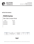
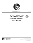
One Jake Brown Road
Old Bridge, NJ 08857-1000 USA
(800) 523-6049 • (732) 679-4000 • FAX: (732) 679-4353
www.blondertongue.com
INSTRUCTION MANUAL
ZFMSM
Agile FM Stereo Modulator
Stock No. 5872
Description
The ZFMSM is a low cost, professional quality, agile FM stereo modulator. The unit accepts either monaural or stereo
(left & right) inputs and modulates the input to any standard FM channel assignment in the frequency range of 88-108
MHz. Frequency selection is via a front panel up/down switch with a digital display. The ZFMSM modulator retains
the frequency setting in the event of power interruption. The modulator can be used in a stand alone configuration
with the ZSCA-FM wide band (88-108 MHz) amplifier. An output test port allows for easy setup and testing without
disrupting service. All controls and test ports are located on the front panel for ease of operation.
Features
•
•
•
•
•
ack Mountable - 1 EIA (1.75") Rack Space
R
High Performance FM Audio Modulator
Superior Signal to Noise and Audio Separation Performance
Switchable Mono or Stereo Capability
Front Panel Level Controls, Power Indicator, Rear AC Convenience Outlet
651214600C
©2009 Blonder Tongue Laboratories, Inc. All rights reserved. Specifications are subject to change without notice. Trademarks are the property of their respective owner.
2
ZFMSM
Instruction Manual
The STOP sign symbol is intended to alert you to the presence of REQUIRED operating and maintenance
(servicing) instructions that if not followed, may result in product failure or destruction.
The YIELD sign symbol in intended to alert you to the presence of RECOMMENDED operating and maintenance
(servicing) instructions.
The LIGHTNING flash symbol is intended to alert you to the presence of uninsulated "dangerous voltage"
within the product's enclosure that may be sufficient magnitude to constitute a risk of electrical shock.
TO REDUCE THE RISK OF ELECTRICAL SHOCK, DO NOT REMOVE COVER FROM THIS UNIT.
NO USER-SERVICEABLE PARTS INSIDE. REFER SERVICING TO QUALIFIED SERVICE PERSONNEL.
WARNING: TO PREVENT FIRE OR SHOCK HAZARD, DO NOT EXPOSE THIS UNIT TO RAIN OR MOISTURE
NOTE TO CATV SYSTEM INSTALLER
This reminder is provided to call the CATV System Installer’s attention to Article 820-40 of the NEC that provides guidelines for
proper grounding and, in particular, specifies that the cable ground shall be connected to the grounding system of the building, as
close to the point of cable entry as practical.
Safety Instructions
You should always follow these instructions to help ensure
Against injury to yourself and damage to your equipment.
➥ Read all safety and operating instructions before you operate the unit.
➥ Retain all safety and operating instructions for future reference.
➥ Heed all warnings on the unit and in the safety and operating instructions.
➥ Follow all installation, operating, and use instructions.
➥ Unplug the unit from the AC power outlet before cleaning. Use only a damp cloth for cleaning the exterior of the unit.
➥ Do not use accessories or attachments not recommended by Blonder Tongue, as they may cause hazards, and will void the warranty.
➥ Do not operate the unit in high-humidity areas, or expose it to water or moisture.
➥ D
o not place the unit on an unstable cart, stand, tripod, bracket, or table. The unit may fall, causing serious personal injury and damage to the
unit. Install the unit only in a mounting rack designed for 19” rack-mounted equipment.
ZFMSM 3
Instruction Manual
Safety Instructions - continued
➥ D
o not block or cover slots and openings in the unit. These are provided for ventilation and protection from overheating. Never place the
unit near or over a radiator or heat register. Do not place the unit in an enclosure such as a cabinet without proper ventilation. Do not mount
equipment in the rack space directly above or below the unit.
➥ O
perate the unit using only the type of power source indicated on the marking label. Unplug the unit power cord by gripping the plug, not the
cord.
➥ T he unit is equipped with a three-wire ground-type plug. This plug will fit only into a ground-type power outlet. If you are unable to insert the
plug into the outlet, contact an electrician to replace the outlet. Do not defeat the safety purpose of the ground-type plug.
➥ R
oute power supply cords so that they are not likely to be walked on or pinched by items placed upon or against them. Pay particular attention
to cords at plugs, convenience receptacles, and the point where they exit from the unit.
➥ B
e sure that the outdoor components of the antenna system are grounded in accordance with local, federal, and National Electrical Code (NEC)
requirements. Pay special attention to NEC Sections 810 and 820. See the example shown in the following diagram:
➥ W
e strongly recommend using an outlet that contains surge suppression or ground fault protection. For added protection during a lightning
storm, or when the unit is left unattended and unused for long periods of time, unplug it from the wall outlet and disconnect the lines between
the unit and the antenna. This will prevent damage caused by lightning or power line surges.
➥ D
o not locate the antenna near overhead power lines or other electric light or power circuits, or where it can fall into such power lines or circuits.
When installing the antenna, take extreme care to avoid touching such power lines or circuits, as contact with them can be fatal.
➥ Do not overload wall outlets or extension cords, as this can result in a risk of fire or electrical shock.
➥ N
ever insert objects of any kind into the unit through openings, as the objects may touch dangerous voltage points or short out parts. This could
cause fire or electrical shock.
➥ D
o not attempt to service the unit yourself, as opening or removing covers may expose you to dangerous voltage and will void the warranty. Refer
all servicing to authorized service personnel.
➥ Unplug the unit from the wall outlet and refer servicing to authorized service personnel whenever the following occurs:
❏ The power supply cord or plug is damaged;
❏ Liquid has been spilled, or objects have fallen into the unit;
❏ The unit has been exposed to rain or water;
❏ The unit has been dropped or the chassis has been damaged;
❏ The unit exhibits a distinct change in performance.
➥ W
hen replacement parts are required, ensure that the service technician uses replacement parts specified by Blonder Tongue. Unauthorized
substitutions may damage the unit or cause electrical shock or fire, and will void the warranty.
➥ U
pon completion of any service or repair to the unit, ask the service technician to perform safety checks to ensure that the unit is in proper
operating condition.
Returning Product for Repair (or Credit)
A Return Material Authorization (RMA) Number is required on all products returned to Blonder Tongue, regardless if
the product is being returned for repair or credit. Before returning product, please contact the Blonder Tongue Service
Department at 1-800-523-6049, Ext. 4256 or visit our website: www.blondertongue.com for further information.
4
ZFMSM
Instruction Manual
Controls and Connections
FRONT PANEL
POWER
ZFMSM
AGILE FM MODULATOR
M
1
REAR PANEL
RF OUT
100.3
FREQ.
R
AUDIO IN
2
3
S
4
TEST
POINT
AUDIO
MODULATION
R.F.
OUTPUT
ADJ.
LEVEL
-20 dB
5
6
7
L
120 VAC
60 Hz, 10 W
600W MAX.
8
9
10
[1] Power Indicator:
LED illuminates to indicate presence of power
[2] Frequency Display:
Seven segment display indicates FM frequency setting
[3] Frequency Select Controls:
Push buttons used to select desired frequency
[4] mono/stereo switch:
Slide switch used to select mono or stereo modes
[5] audio modulation level:
Adjusts aural carrier modulation
[6] RF Output level:
Adjusts RF output
11
12
[7] -20 dB Test Point:
Externally accessible for in-service testing
[8] RF OUtput:
RF signal is connected to distribution system
[9] audio in:
Connect a 1 V p-p (2 V p-p max.) mono or stereo signal
source from a satellite receiver or VCR
[10] Convenience outlet:
Allows looping of power between units
[11] Power Cord:
Three prong power cord connects to a 120 VAC outlet
Specifications (Typical)
RF
Frequency Range: 88-108 MHz
Frequency Step: 100 kHz
Output Level: +35 dBmV
Output Level Adjust: 10 dB
Frequency Stability: ±10 kHz
Audio Input Level: 0.2 to 2.0 V p-p
Audio Frequency Range: 30 Hz to 15 kHz
Audio S/N Ratio: >60 dB
Audio Seperation: >30 dB
General
Power Requirements
Voltage: 120, ±10% VAC
Frequency: 60 Hz
Power: 10 W
Temperature Range: 0 to +50 °C
Mechanical
Dimensions (W x H x D): 19.0 x 1.75 x 3.01 in.; 483 x 44 x 76 mm
Weight: 5 lbs.; 2.1 kg
Controls (Top Panel)
Audio Input: L/R "F" Type Female
RF Output: "F" Type Female
Test Port: "F" Type Female
Connectors (Top Panel)
Frequency Setting: Up/Down Control
Aural Modulation Adj: Control
RF Output Level: Control
Indicators
Power ON: LED, Red
Frequency Display: 4 Digit LED Screen
One Jake Brown Road
Old Bridge, NJ 08857-1000 USA
(800) 523-6049 • (732) 679-4000 • FAX: (732) 679-4353
www.blondertongue.com