1
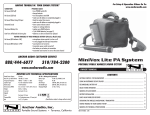
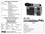
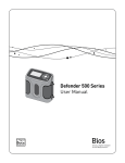
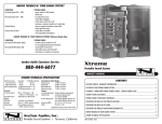
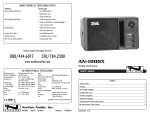
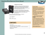
HAVING TROUBLE W/ YOUR SOUND SYSTEM?
CONDITION
No Sound (power LED off)
Charge Indicator LED off
No Sound (power LED on)
Shortened Battery Life
Distorted Sound
Excessive Hum or Noise
POSSIBLE SOLUTION
• turn POWER switch ON
• charge battery or plug in AC cord
• leave plugged in for 48 hours to repair battery
• check for output from source
• make sure all cables are completely plugged in
• turn up volume control of input used
• remove plug from speaker output if not using external speaker output
• charge battery fully; if battery life continues to deteriorate, contact
Anchor Audio customer service: 888/444-6077
• lower system volume control
• use shielded cables
• use balanced microphone
HAVING TROUBLE W/ YOUR WIRELESS SYSTEM? (WIRELESS MODELS ONLY)
CONDITION
No Sound (RX Indicator: ON)
No Sound (RX Indicator: OFF)
POSSIBLE SOLUTION
• set MUTE switch to on (handheld mic only)
• turn up WIRELESS volume control
• make sure mic is plugged into body pack transmitter
• push mic power button
• turn Explorer PRO POWER switch on
• make sure transmitter power switch is on
• set receiver and transmitter to same channel
• replace battery in transmitter
NEED MORE HELP? View demonstration videos on proper system setup and
operation at our website - www.anchoraudio.com
ANCHOR AUDIO CUSTOMER SERVICE
888/444-6077
310/784-2300
EXPLORER PRO TECHNICAL SPECIFICATIONS
Rated Power Output
Max SPL @ Rated Power
Frequency Response
AC Power Reqs.
Dimensions (HWD)
Weight
Inputs
Microphone
(2 combo jacks)
Auxiliary
75 watts AC / DC mode
110 dB @ 1 meter
80 Hz – 16 kHz
90 – 264 VAC, 50/60 Hz
16.5 x 10.5 x 10” / 42 x 27 x 25 cm
23 pounds / 10.4 Kg
Lo-Z (1 k ohm), balanced, XLR
12 VDC condenser mic phantom pwr
Hi-Z (10 k ohm), unbal, 1/4” phone
Hi-Z (10 k ohm), unbal, 1/8” & 1/4”
Sensitivity For Rated Output
Line
-8.4 dBV (380 mVrms)
Mic (unbal & bal)
-49 dBV (3.63 mVrms)
Outputs
Line (post fader)
Lo-Z, buffered, 1/4” balanced
Speaker
4-pole Neutrik Speakon® jack
EXPLORER PRO
PORTABLE SOUND SYSTEM
OWNER’S MANUAL
CONTENTS
GETTING STARTED ................................................................................................................................................. 2
SETTING UP YOUR EXPLORER PRO SOUND SYSTEM ......................................................................................... 2/3
FEEDBACK / SPEAKER STAND SETUP .................................................................................................................... 3
EXPLORER PRO SOUND SYSTEM BASIC OPERATION............................................................................................. 4
CARING FOR YOUR BUILT-IN BATTERY / STEREO LINE INPUT JACK..................................................................... 4
EXPLORER PRO ACCESSORIES................................................................................................................................ 6
OPERATING THE BUILT-IN UHF WIRELESS RECEIVER ........................................................................................... 6
(Specifications subject to change without notice)
OPERATING THE WIRELESS MICROPHONE / TRANSMITTER ................................................................................. 7
HAVING TROUBLE W/ YOUR SOUND SYSTEM? ...................................................................................................... 8
Anchor Audio, Inc.
Portable Sound Systems • Torrance, California
EXPLORER PRO SOUND SYSTEM TECHNICAL SPECIFICATIONS ............................................................................ 8
100-0172-000/A - 3/08
A MESSAGE FROM THE OWNER
OPERATING THE WIRELESS MICROPHONE / TRANSMITTER
Thank you for choosing an Anchor Audio portable sound system. Our products incorporate state-of-the-art design and the finest
quality of materials and workmanship. We’re proud of our products and appreciate the confidence which you have shown by selecting an Anchor system.
CHANNEL SELECTION - HANDHELD TRANSMITTER
1. Unscrew battery cover on bottom of microphone
I hope you’ll take a few minutes to review this manual. We’ve incorporated several unique features into our products, and your
knowledge of how to use them will enhance the performance and your enjoyment of the system.
2. Set the CHANNEL SELECTOR dial to match the
channel setting of your receiver
3. Replace battery cover and tighten firmly
CHANNEL SELECTION - BODY-PACK TRANSMITTER
1. The channel selection dial is located on the
side of the transmitter
2. Set the CHANNEL selection dial to match
the channel setting of the receiver
Janet Jacobs – President
on behalf of all Anchor Employees
GETTING STARTED
Please check your new unit carefully for any damage which may have occurred during shipment. Each Anchor product is carefully
inspected at the factory and packed in specially designed boxes for safe transport.
Notify the freight carrier immediately of any damage to the shipping box or product. Repack the unit in the original box and wait
for inspection by the carrier’s claim agent. Notify your dealer of the pending freight claim.
NOTE: All damage claims must be made with freight carrier!
RETURNING SYSTEMS FOR SERVICE OR REPAIR
For service or repair, please contact the dealer you purchased your system from or Anchor Audio Customer Service at 888/444-6077
to obtain a RA (Return Authorization) number. All shipments to Anchor Audio must include an RA number and must be shipped
prepaid. C.O.D. shipments will be refused and returned at your expense.
IMPORTANT: Save the shipping box & packing materials,
they were specially designed to ship your unit!
WARRANTY REGISTRATION
Visit our website at www.anchoraudio.com and select “Warranty Registration”. Complete the online form to activate the six-year
limited warranty on your Explorer PRO sound system and two-year limited warranty for the CD player and microphones.
SETTING UP YOUR EXPLORER PRO SOUND SYSTEM
We recommend placing your sound system between the audience and the presenter, facing the audience and raised above their
heads using a speaker stand or table. This benefits listeners in the rear of the crowd, minimizes the risk of overpowering those
in the front and helps prevent feedback by keeping microphone users behind the sound system.
SINGLE SYSTEM PLACEMENT
Place your unit along the least trafficked aisle pointing
towards the center of the audience.
2
MULTIPLE SYSTEM PLACEMENT
Place units along aisles pointing just off the audience
center line, over the crowds head. With the sound system
placed properly it should provide sufficient coverage.
Waste electrical and electronic products must not be
disposed of with household waste. Please recycle
where facilities exist. Check with your Local Authority
or Retailer for recycling advice.
NOTE: When using dual wireless, each microphone must be set to a different channel!
USING YOUR WIRELESS MICROPHONES
After you have set the transmitter channel (see above) you are ready to use your wireless microphone:
1. Body-pack transmitter users must insert the mic
plug into the transmitter jack marked MIC
2. Turn the transmitter power switch to ON
(The red LED will flash when the mic is turned on.
If the red LED stays on, the battery is low)
3. Turn the Explorer PRO power switch to ON
4. The RX indicators will light (only one indicator
will light at a time) when the wireless signal is
being transmitted and received
CAUTION: Harmful feedback may occur when walking in front of a sound system or
speaker with a wireless microphone. Always point microphone away from speakers!
REPLACE BATTERY - HANDHELD TRANSMITTER
1. Unscrew battery cover on bottom of microphone
REPLACE BATTERY - BODY-PACK TRANSMITTER
1. Slide open battery cover on front of transmitter
2. Replace old batteries with 2 fresh size ‘AA’
alkaline batteries
2. Replace old batteries with 2 fresh size ‘AA’
alkaline batteries
3. Replace battery cover and tighten firmly
3. Replace battery cover by sliding firmly into place
NOTE: Transmitter power must be OFF when changing batteries!
7
DIVERSITY WIRELESS BY ANCHOR AUDIO
FEEDBACK
Anchor Audio UHF wireless is a 16 channel, diversity wireless system that receives signals with two independent antennae.
With diversity wireless the receiver processes the stronger signal, effectively minimizing dropouts and interference from other
transmitting sources. The antennae are mounted internally so there are no obstructions or risk of damage.
CHANNEL SELECTION - BUILT-IN RECEIVER
Select a channel, set the built-in receiver & microphone transmitter to that channel before using
your wireless system.
1. Choose any available wireless channel/
frequency from 1 thru 16
(see page 7 for transmitter instructions)
WIRELESS 1 CHANNEL
SELECTION
WIRELESS 2 CHANNEL
SELECTION
WIRELESS 2
RX INDICATOR
LIGHTS
WIRELESS 1
RX INDICATOR
LIGHTS
WRONG SYSTEM PLACEMENT
• Sound reflecting off hard surfaces
AVOIDING & ELIMINATING FEEDBACK
• Point microphone in a different direction
• Reduce the sound system volume levels
WIRELESS 1
VOLUME CONTROL
WIRELESS 2
VOLUME CONTROL
EXPLORER PRO ACCESSORIES
EXP-7501- Explorer PRO Companion Speaker
Unpowered companion speaker (speaker cable not included)
SC-50NL - Heavy Duty Speaker Cable
50’ speaker cable, connect EXP-7501 to powered Explorer PRO
SS-550 - Heavy Duty Speaker Stand
Adjustable stand made of black, anodized aluminum
NL-EXP - Storage Cover
Durable nylon fitted speaker storage/dust cover
HC-1620 - Hard Case
For travel or storage - holds one Explorer PRO & accessories
EXP-SOFT-TOTE - Soft Rolling Case
Soft case w/ wheels & handle for Explorer, stand & accessories
ANCHOR WIRELESS – 16 CHANNEL UHF
WH-6000 - Handheld Microphone/Transmitter
WB-6000 - Body Pack Transmitter
Works w/ hands free microphones (mic not included)
Body Pack Transmitter Microphones:
CM-60 - Collar Microphone
Lightweight, low-profile mic
EM-60T - UltraLite Microphone
Hands free “Over-the-Ear” mic
LM-60 - Lapel Microphone
Lightweight, clip-on lapel mic
HBM-TA4F - Headband Microphone
Ultra-lightweight headband mic
CERTIFICATION
This system conforms to part 74 and part 15 of the FCC rules, contact the FCC office for filling forms.
Frequency Range: 682 MHz - 698 MHz
6
CORRECT SYSTEM PLACEMENT
• Volume setting is too loud for room
• Place speaker in FRONT of the microphone
NOTE: Ongoing wireless interference? The frequency you selected may be in use by
other systems in the area! Change channels until you find a clear frequency!
MIC-90 - Handheld Wired Microphone
Anchor’s dynamic, balanced, low impedance microphone
FEEDBACK CAUSES
• Microphone too close, pointing towards
or in front of speaker
• Keep microphone away from the speaker
2. Set the Wireless Channel Selector Knob to
the channel/frequency you choose in step 1
If you have two wireless receivers repeat above
for the second receiver. Remember each receiver/
transmitter pair must be set to different channels
to avoid interference.
Feedback, a howling noise or shrill sound, is self-generated by the sound system. It’s caused by a microphone picking up the sound
coming from the speaker and then re-amplifying it. Once a feedback loop starts it continues until the system is adjusted.
WH-6000EU and WB-6000EU transmitters meet the essential requirements of the European R&TTE
Directive 99/5/EC and are eligible to carry the CE marking. CE 0336 !
European Frequency Range: 863.125 MHz - 864.875 MHz
CAUTION: Feedback can damage your equipment & may be hazardous to hearing.
CONNECTING TWO OR MORE EXPLORER PRO SOUND SYSTEMS
USING A EXPLORER PRO UNPOWERED COMPANION SPEAKER (EXP-7501)
Connect one end of a speaker cable (SC-50NL) to the SPEAKER OUT jack on the back of a powered Explorer PRO sound system.
Connect the other end to the jack labeled IN on the back of a Explorer PRO unpowered companion speaker.
NOTE: AC power is not required for an unpowered companion speaker.
USING 2 POWERED EXPLORER PRO SOUND SYSTEMS
This method uses the line-output feature of your Explorer PRO sound system. Connect a speaker cable (1/4” phone) from the
LINE OUT jack on the first powered Explorer PRO to the LINE IN jack on the second powered Explorer PRO. Set the volume of
the second Explorer PRO to maximum so that full volume control will be at the first or primary sound system.
NOTE: The line-output feature can also be used to send the signal to a sound
system in a different room or a separate recording device.
SPEAKER STAND SETUP
1. Loosen the Lower Collar Knob
2. Separate the stand legs until
the leg support Cross Braces
are parallel to the floor
3. Tighten the Lower Collar Knob
LOWER
COLLAR
KNOB
UPPER
COLLAR
KNOB
SPEAKER STAND ADAPTER
The 1.5” dia. Speaker Stand Adapter lets
you mount the Explorer on a speaker stand.
4. Loosen the Upper Collar Knob
and extend the center pole
1. Slide Speaker Stand Adapter into
slot on Explorer PRO bottom
5. Adjust height and retighten the
Upper Collar Knob
3. Place unit on stand carefully
6. Place your Anchor sound system
on the stand
2. Tighten screw to secure adapter
CROSS BRACES
4. Tighten screw on Adapter collar
securing Explore PRO on stand
3
BASIC SYSTEM OPERATION
LINE OUT - OUTPUT JACK
NOTE: Fully Charge Battery Before First DC Use!
1. Set all Input Level Controls to minimum & Tones Controls to flat
or the middle setting before turning your system on
WIRELESS RECEIVERS 1 & 2
(see page 6)
LINE IN - INPUT JACKS
Balanced 1/4” – provides a combined
output of all active system inputs
The 1/8” (3.5 mm) jack input is used to hook up an iPod, a portable CD/
MP3/ tape player, laptop computer, or similar external audio source
Record your presentation or connect to
another powered sound system
The 1/4” unbalanced input can be used for other communication devices
including a mixer or daisy chaining together multiple Explorer speakers
2. Plug a wired microphone into the MIC 1 or MIC 2 jacks and/or
plug an audio source into the LINE-IN jack
3. Switch POWER to ON, the BATTERY LED will light
4. Slowly increase the Level Control for the input jacks used
to the desired volume
5. Adjust BASS & TREBLE controls to desired sound quality
IMPORTANT: Make all connections w/ shielded
cables to avoid hum, buzzing or interference.
NEED MORE HELP? Visit Our Website:
www.anchoraudio.com
CARING FOR YOUR BUILT-IN BATTERY
An automatic charging system is built-in to your Explorer PRO Sound System.
It is designed to properly charge and maintain the systems built-in battery.
CHARGING THE BATTERY
LINE IN LEVEL CONTROL
RX INDICATOR LIGHTS FOR
WIRELESS RECEIVER 1
A solid red light on one of the RX Indicator
Lights indicates that the sound system is getting
good reception with the wireless microphone
TONE CONTROLS - BASS/TREBLE
A solid red light on both RX Indicator Lights
indicates that the sound system is getting optimum reception with the wireless microphone
WIRED MIC LEVEL CONTROLS
RX INDICATOR LIGHTS FOR
WIRELESS RECEIVER 2
WIRELESS MICROPHONE 1
LEVEL CONTROL
MUSIC/ SPEECH BUTTON
In situations where you’re speaking to a
larger crowd or in a noisy environment, just
push the Music/Speech button in and give
your voice an added boost
Adjust knob to control
wireless microphone levels
WIRELESS MICROPHONE 2
LEVEL CONTROL
To return back to normal use, just push the
Music/Speech button again
1. The Battery Level Indicator Light will show a flashing red light
when battery is low
2. To charge the battery, plug the AC power cord into the Explorer PRO
3. Plug the other end of the cord into AC outlet
4. The Charge Indicator Light will show flashing green light when
charging is complete
To preserve the life of your battery it is recommended that it be fully charged as
soon as possible after every use regardless of the length of operation.
NOTE: System Can Be Used While Battery Charges!
OPERATING IN AC MODE
Plug your sound system into an AC outlet. Operate the system normally while
the built-in battery charges automatically. The Charge Indicator Light will
show a solid green light when battery is charging and a flashing green light
when charging is complete.
IMPORTANT: Always Store Your System w/
Battery Fully Charged!
4
VOICE OVER BUTTON
Push the “Voice Over” button in to have
the music automatically lowered when you
speak through a connected microphone
AC POWER CORD INLET
EXPLORER PRO SOUND SYSTEM
CONTROL PANEL
Music will return to original level when you
mic use/speaking stops
POWER SWITCH
Model Shown: EXP-7500U2
BATTERY LEVEL INDICATOR LIGHT
The Explorer PRO sound system features a built in Battery Level Indicator Light that
shows the battery level in two steps at power on.
BATTERY LEVEL INDICATOR LIGHT
CHARGE INDICATOR LIGHT
SPEAKER OUT - OUTPUT JACK
Connect the system to a Explorer PRO
unpowered companion speaker
CHARGE INDICATOR LIGHT
The Explorer PRO sound system is equipped with a built in rapid charger, designed to
quickly charge and maintain the battery. If the Charge Indicator Light is:
1. RED (solid): Battery is ready for use
GREEN (solid): Battery is in good condition, rapid charging has begun
2. RED (flashing): Battery level becoming low
(system auto-shut off in 45-60 minutes)
GREEN (flashing): Battery is fully charged