1
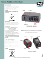
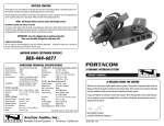
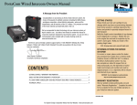
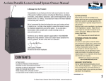
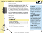
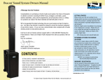
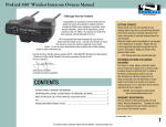
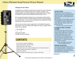
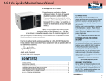
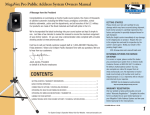
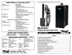
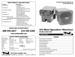
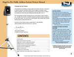
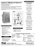
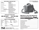
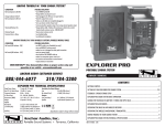
PortaCom Wired Intercom Owners Manual
MADE IN USA
TWO YEAR WARRANTY
A Message from the President
Congratulations on purchasing an Anchor Audio intercom system, the
choice of thousands of satisfied customers including the White House,
prestigious universities, school districts nationwide, police and fire
departments, and all branches of the U.S. Military. Our products are made
of the finest materials and built with pride in the U.S.
We’ve incorporated the latest technology into your intercom system yet
kept it simple to use. Just take a few minutes to review this manual to
ensure the maximum enjoyment of your Anchor system. Or, you can view a
demonstration video complete with a trouble shooting section at
www.anchoraudio.com.
Feel free to call our friendly customer support staff at 1-800-ANCHOR1
with any questions. We love to hear from our customers.
GETTING STARTED
Please check your new unit carefully for any
damage which may have occurred during shipment.
Each Anchor product is carefully inspected at the
factory and packed in specially designed boxes for
safe transport.
Notify the freight carrier immediately of any damage
to the shipping box or product. Repack the unit
in the original box and wait for inspection by the
carrier’s claim agent. Notify your dealer of the
pending freight claim.
NOTE: All damage claims must be made with freight carrier!
RETURNING SYSTEMS FOR SERVICE
OR REPAIR
Janet Jacobs, President
on behalf of all Anchor employees
CONTENTS
GETTING STARTED ................................................................................................................. 1
BASIC SYSTEM OPERATION / WHAT IS PORTACOM?.................................................................. 2
PC-2000 POWER CONSOLE / BP-2000 BELTPACKS / H-2000 AND H-2000S HEADSETS............ 3
For service or repair, please contact the dealer
you purchased your system from, call us at 1-800262-4671, or visit www.AnchorAudio.com, Contact
Us page. Our tech support team will issue an RA
number for warranted systems, after which, you can
ship the item(s) to Anchor for repair. All shipments
to Anchor Audio must include an RA number and
must be shipped prepaid. C.O.D. shipments and
shipments without an RA number will be refused
and returned at your expense.
IMPORTANT: Save the shipping box & packing materials,
they were specially designed to ship your unit!
IMPORTANT SAFETY INFORMATION.......................................................................................... 4
TECHNICAL SPECS.................................................................................................................. 5
For System Setup & Operation Videos Visit Our Website: www.anchoraudio.com
1
PortaCom Wired Intercom Owners Manual
MADE IN USA
TWO YEAR WARRANTY
What is PortaCom?
PortaCom Intercom System is a portable two-channel communication device that’s simple to
set up and easy to use. The main system components include:
PC-2000 Power Console, BP-2000 Belt Packs &
H-2000 & H-2000S Headsets
Station-to-station connections are made using standard microphone cable with 3-pin XLR
connectors.
The PC-2000 Power Console has four output jacks to make a 4-headset system. You can
add more headsets/users to the system by using the B3-2000 Branch Box to expand and
reconfigure your system for use in almost any situation.
A typical 6-headset system using one B3-2000 is illustrated here:
BASIC SYSTEM OPERATION
1. Plug headset connector into 4-pin XLR Headset Jack on belt pack
2. Plug AC adapter into standard 110V AC outlet (230V AC export)
then into AC Input Jack on the PC-2000 Power Console
3. Connect BP-2000 Belt Packs to the Output Jacks on the PC2000
NOTE: Make connections w/ standard mic cables.
4.
5.
6.
7.
Set the PC-2000 Power Switch to “on”
Adjust headset boom so microphone is close to mouth
Adjust listening level w/ Headset Volume Control on Belt Pack
Use Channel Switch to select between channel A or B
B3-2000
NOTE: The Optional RM-100 Rackmount Allows
1 or 2 PC-2000’s To Mount In Standard Racks.
PC-2000
For System Setup & Operation Videos Visit Our Website: www.anchoraudio.com
2
PortaCom Wired Intercom Owners Manual
MADE IN USA
PC-2000 Power Console
The PC-2000 Power Console can power up to 20 BP-2000 Belt Packs over
a combined total of 2,500 feet of cable. It has a power switch, an input for
connecting the AC adapter and four 3-pin XLR output jacks.
Using the RM-100 bracket you can mount one or two PC-2000s in a
standard rack.
Belt packs are connected to the PC-2000 using standard mic cable with
3-pin XLR connectors.
TWO YEAR WARRANTY
POWER SWITCH
AC/DC INPUT JACK
BP-2000 Belt Pack
The BP-2000 Belt Pack has a female, 3-pin XLR, Line Input Jack and a
male, 4-pin XLR, Headset Jack. Both jacks are located on the bottom side
of the belt pack. Power is supplied through the microphone cable by the
PC-2000 Power Console.
The BP-2000 controls can be found on the belt pack top and feature:
Headset Volume Control, A/B Channel Switch,
Mic Mute Button & Call Light & Button
The Headset Volume Control adjusts only the individual headset listening
level, not the volume level of the entire system.
Setting the Mic Mute Button to “on” enables the headset microphone.
Setting the button to “off” will short or mute the microphone. The Mic Mute
Button does not affect the headset listening volume.
Pushing the Call Button will light the Call Light on all belt packs connected
to the system. Use the Call Light to alert any users who may not be wearing
their headsets.
POWER INDICATOR LIGHT
OUTPUT JACKS
PC-2000 Power Console - control panel
NEED MORE HELP? View demonstration videos on proper system setup and operation at our website: www.anchoraudio.com
NOTE: Custom length microphone cables are available from Anchor Audio.
A/B CHANNEL SWITCH
MIC MUTE BUTTON
HEADSET JACK
H-2000 & H-2000S portacom Headsets
PortaCom comes with single-earpiece (H-2000S) and/or dual-earpiece (H2000) headsets. To use plug the headset cable into the bottom of the
BP-2000 Belt Pack. Adjust the headset listening level using the Headset
Volume Control on the belt pack.
The headset’s female 4-pin XLR connector plugs into the 4-pin XLR jack on
the bottom of the belt pack. A wiring diagram of the headset connector is
shown at right.
VOLUME KNOB
CALL LIGHT
CALL BUTTON
LINE INPUT JACK
Pb-2000 belt pack - top/bottom
For System Setup & Operation Videos Visit Our Website: www.anchoraudio.com
3
PortaCom Wired Intercom Owners Manual
MADE IN USA
TWO YEAR WARRANTY
Important Safety Instructions
1) Read Instructions – All the safety and operation instructions should be read before the product is operated.
2) Retain Instructions – The safety and operating instructions should be retained for future
reference.
3) Heed Warnings- All warnings on the product and in the operating instructions should be adhered to.
4) Follow Instructions – All operating and use instructions should be followed.
5) Cleaning – Unplug this product from the wall outlet before cleaning. Do not use liquid
cleaners or aerosol cleaners. Use a damp cloth for cleaning.
Exception: A product that is meant for uninterrupted service and that for some specific
reason, such as the possibility of the loss of an authorization code for the CATV converter,
is not intended to be unplugged by the user for cleaning or any other purpose, may
exclude the reference to unplugging the product in the cleaning description otherwise in
above 5).
6) Attachments – Do not use attachments not recommended by the product manufacturer
as they may cause hazards.
7) Water and Moisture – Do not use this product near water – for example, near a bath tub,
wash bowl, kitchen sink, or laundry tub; in a wet basement; or near a swimming pool;
and the like.
8) Accessories – Do not place this product on an unstable cart, stand, tripod, bracket, or
table. The product may fall, causing serious injury to a child or adult, and serious damage
to the product. Use only with a cart, stand, tripod, bracket, or table recommended by the
manufacturer, or sold with the product. Any mounting of the product should follow the
manufacturer’s instructions, and should use a mounting accessory recommended by the
manufacturer.
9) A product and cart combination should be moved with care. Quick stop, excessive force,
and uneven surfaces may cause the product and cart combination to overturn.
10) Ventilation – Slots and openings in the cabinet are provided for ventilation and to ensure
reliable operation of the product and to protect it from overheating, and these openings
must not be blocked or covered. The openings should never be blocked by placing the
product on a bed, sofa, rug, or other similar surface. This product should not be placed in
a build-in installation such as a bookcase or rack unless proper ventilation is provided or
the manufacturer’s instructions have been adhered to.
11) Power Sources – This product should be operated only from the type of power source
indicated on the marking label. If you are not sure of the type of power supply to your
home, consult your product dealer or local power company. For products intended to
operate from battery power, or other sources, refer to the operating instructions.
12) Grounding or Polarization – This product may be equipped with a polarized alternatingcurrent line plug (a plug having one blade wider than the other). This plug will fit into
the power outlet only one way. This is a safety feature. IF you are unable to insert the
plug fully into the outlet, try reversing the plug. If the plug should still fail to fit, contact
your electrician to replace your obsolete outlet. Do not defeat the safety purpose of the
polarized plug.
13) Power-Cord Protection – Power-supply cords should be routed so that they are not likely
to be walked on or pinched by items placed upon or against them, paying particular
attention to cords at plugs, convenience receptacles, and the point where they exit from
the product.
14) Protective Attachment Plug – The product is equipped with an attachment plug having
overload protection. This is a safety feature. See Instruction Manual for replacement or
resetting of protective device. If replacement of the plug is required, be sure the service
technician has used a replacement plug specified by the manufacturer that has the same
overload protection as the original plug.
15) Outdoor Antenna Grounding – If an outside antenna or cable system is connected to
the product, be sure the antenna or cable system is grounded so as to provide some
protection against voltage surges and built-up static charges. Article 810 of the National
Electrical Code, ANSI/NFPA 70, provides information with regard to proper grounding of
the mast and supporting structure grounding of the lead in wire to an antenna discharge
unit, size of grounding conductors, location of antenna-discharge unit, connection of
grounding electrodes, and requirements for the grounding electrode. See Figure A.
16) Lightning – For added protection this product during lightning storm, or when it is left
unattended and unused for long periods of time, unplug it from the wall outlet and
disconnect the antenna or cable system. This will prevent damage to the product due to
lightning and power-line surges.
17) Power Lines – An outside antenna system should not be located in the vicinity of
overhead power lines or other electric light or power circuits, or where it can fall into
such power lines or circuits. When installing an outside antenna system, extreme care
should be taken to keep from touching such power lines or circuits as contact with them
might be fatal.
18) Overloading – Do not overload wall outlets, extension cords, or integral convenience
receptacles as this can result in a risk of fire or electric shock.
19) Object and Liquid Entry – Never push objects of any kind into this product through
openings as they may touch dangerous voltage points or short-out parts that could result
in a fire or electric shock. Never spill liquid of any kind on the product.
20) Servicing – Do not attempt to service this product yourself as opening or removing
covers may expose you to dangerous voltage or other hazards. Refer all servicing to
qualified service personnel.
21) Damage Requiring Service – Unplug this product from the wall outlet and refer servicing
to qualified service personnel under the following conditions:
a.When the power-supply cord or plug is damaged.
b.If liquid has been spilled, or objects have fallen into the product.
c. If the product has been exposed to rain or water.
d.If the product does not operate normally by following the operating
instructions. Adjust only those controls that are covered by the operating
instructions as an improper adjustment of other controls may result in damage and will often require extensive work by a qualified technician to restore the product to its normal operation.
e.If the product has been dropped or damaged in any way.
f. When the product exhibits a distinct change in performance – this indicates a need for service.
22) Replacement Parts – When replacement parts are required, be sure the service
technician has used replacement parts specified by the manufacturer or have the same
characteristics as the original part. Unauthorized substitutions may result in fire, electric
shock, or other hazards.
23) Safety Check – Upon completion of any service or repairs to this product, ask the service
technician to perform safety checks to determine that the product is in proper operation
condition.
24) Wall or Ceiling Mounting – The product should be mounted to a wall or ceiling only as
recommended by the manufacturer.
25 Heat – The product should be situated away from heat sources such as radiators, heat
registers, stoves, or other products (including amplifiers) that produce heat.
For System Setup & Operation Videos Visit Our Website: www.anchoraudio.com
4
PortaCom Wired Intercom Owners Manual
MADE IN USA
TWO YEAR WARRANTY
PoRtacom TECHNICAL SPECIFICATIONS
Operating Distance
Normal Line Level
Signal-to-Noise Ratio
Distortion
Connecting Cables
Compatibility
B3-2000 – Branch Box
Connectors (3-pin XLR)
Dimensions
Weight
BP-2000 – Belt pack
Input Line Connector
Headset Connector
Bridging Impedance
DC Current Reqs.
Dimensions
Weight
Up to 2,500 ft (total cable length)
-15dBV
-65dB
< 0.5%
Standard 1-pair shielded mic cable
w/ 3-pin XLR (heavy-duty cable
recommended for runs over 250 ft)
Generally compatible w/ industry
standard system (call for info)
Input – 1 female / Output – 3 male
1.9” x 4.1” x 4.25”
(48 x 105 x 108 mm)
19.2 oz / 0.5 kg
3-pin XLR – female
4-pin XLR – male
10k ohm min
20mA max
3.8” x 2.75” x 1.25”
(96.5 x 69.85 x 31.75 mm)
.40 oz. / 0.0113 kg.
H-2000/H-2000S–Dual-Earpiece/Single-Earpiece Headset
Connector
4-pin XLR – female
Microphone Type
Dynamic, low impedance
Dimensions
3.5” x 7.4” x 7.9”
(8.9 x 18.8 x 20 cm)
Weight
H-200 16 oz / .45 kg
H-200S 13 oz / .37 kg
PC-2000 – Two-Channel Power Console
Output Connectors
3-pin XLR – 4 male
Voltage Output
22 volts DC to belt packs
Max. Current Capacity 400mA
Max. Belt Packs
20 BP-2000 belt packs
Input Power Reqs.
24VAC, 50/60Hz, 750mA;
30 – 40VDC, 500mA
Dimensions
1.75” x 8.5” x 4.5”
(45 x 216 x 114 mm)
Weight
57.6 oz / 1.63 kg
AC Power Adapter
Anchor model AC-20
Input Voltage
120VAC, 60Hz
Output Voltage/Current 24VAC @ 750mA
Anchor Audio Customer Service
800.262.4671
FOR ADDITIONAL INFORMATION
visit www.anchoraudio.com
For System Setup & Operation Videos Visit Our Website: www.anchoraudio.com
5