1
12 CHANNEL
MIXING CONSOLE
User's Manual
12 CHANNEL MIXING CONSOLE
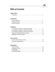
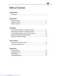
INDEX
01 SAFETY RELATED SYMBOLS
AUX RETURNS
Input
1
Frequency response
Distortion(THD+N)
02 WARNING
1/4' TRS with un-balanced
10Hz to 55KHz,+/-3dB
<0.03% at +0dB ,22Hz~22KHz A-weighted
1
GAIN range
03 IMPORTANT SAFETY INSTRUCTION
2
SNR
Impedances
04 INTRODUCTION
3
Microphone input
05 READY TO START
3
All other input
1.8K
10K or greater
Tape out
1K
04 FEATURES
4
120
05 CONTROL ELEMENTS
5
All other out
DSP section (options)
A/D and D/A converters
24bit
Echo ,Echo+Verb , Tremolo , Plate , Chorus ,Vocal
Rotary , Small Room , Flange + Verb , Large Hall
06 INSTALLATION & CONNECTION
19
06 PRESET LIST
22
Type of effects
07 BLOCK DIAGRAM
08 TECHNICAL SPECIFICATION
23
24
Controls
OFF TO +15dB
<-100dBr A-weighted
100 position preset selector(10 preseter * 10 variation)
Mute switch & Foot-switching with LED indicator
FOOT-SW
TIP:FX
SLEEV:GND
Main mix section
Max. MAIN MIX output
+22dBu XLR balanced (+16dBu un-balanced)
AUX range
OFF to +15dB
Fader range
OFF to +10dB
PHONES/CONTROL-ROOM range OFF to +15dB
Hum & Noise
<-80dB @ 20Hz~22KHz A-weighted
level:0dB,the other :minimum
Crosstalk
<-80dB @0dB 20Hz~22KHz A-weighted
the other :minimum,
Power supply
Main voltage
100-240V ~ 50/60Hz
Fuse
T1.6A AC250V
Rated power consumption
40W
25
1 channel & MAIN
MAIN level:0dB,
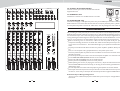
12 CHANNEL MIXING CONSOLE
SAFETY RELATED SYMBOLS
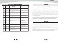
TECHNICAL SPECIFICATIONS
MODEL :
Mono channels
Microphone input
12 channel mixing console
CAUTION
RISK OF ELECTRIC SHOCK
DO NOT OPEN
Distortion(THD+N)
XLR with balanced
10Hz to 55KHz,+/-3dB
<0.03% at +0dB ,22Hz~22KHz A-weighted
Gain range
0dB to 50dB
Max. Input
+15 dB
LOW CUT
75Hz
<-100dBr A-weighted
Frequency response
SNR
Phantom power
Line input
Frequency response
+48V with switch control
1/4' TRS with balanced
Distortion(THD+N)
10Hz to 55KHz,+/-3dB
<0.03% at +0dB ,22Hz~22KHz A-weighted
Sensitivity range
+15dB~ -35dB
COMPRESSOR
THRESHOLD:20dB--->
5dB
Mic input
XLR with balanced
LOW CUT
Line input
75Hz
1/4' TRS or TRS/RCA with un-balanced
Frequency response
10Hz to 55KHz,+/-3dB
<0.03% at +0dB ,22Hz~22KHz A-weighted
Sensitivity range
SNR
Channels EQ
-20dBu~ +20dBu
<-100dBr A-weighted
The symbol is used to indicate that
some hazardous live terminals are
involved within this apparatus, even
under the normal operating conditions.
The external wiring connected to the output
hazardous live terminals requires installation
by an instructed person, or the use of readymade leads or cords.
The symbol is used in the service
documentation to indicate that specific
component shall be only replaced by
the component specified in that
Documentation for safety reasons.
Do not Remove any Cover
Protective grounding terminal.
The cover should be removed by the qualified
personnel only.
No user serviceable parts inside.
There are maybe some areas with high
voltages inside, to reduce the risk of electric
shock, do not remove any cover if the power
supply is connected.
Alternating current /voltage.
ON: Denotes the apparatus turns on.
Fuse
OFF: Denotes the apparatus turns off, because of using the single pole switch, be sure
to unplug the AC power to prevent any
electric shock before you proceed your
service.
To prevent a fire, make sure to use fuses
with specified standard (current, voltage,
type). Do not use a different fuse or short
circuit the fuse holder.
Before replacing the fuse, turn OFF the
apparatus and disconnected the power
source.
WARNING: Describes precautions that
should be observed to prevent the danger
of injury or death to the user.
Protective Grounding
mono channel
stereo channel
High
+/-15dB @12KHz
+/-15dB @12KHz
Mid
+/-15dB @2.5KHz
+/-15dB @2.5KHz
Low
2-TACK IN
+/-15dB @80Hz
+/-15dB @80Hz
TAPE IN
Frequency response
External Connection
Hazardous live terminal .
GAIN:0~9dB
Stereo input channels
Distortion(THD+N)
Unplug this apparatus during lightning
storms or when unused for long periods
of time.
Disposing of this product should
not be placed in municipal waste
and should be separate collection.
Make sure to connect the protective
grounding to prevent any electric shock
before turning ON the apparatus.
Never cut off the internal or external protective grounding wire or disconnect the
wiring of protective grounding terminal.
CAUTION: Describes precautions that
should be observed to prevent danger of the
apparatus.
Operating Conditions
WARNING
RCA jack
Distortion(THD+N)
10Hz to 55KHz,+/-3dB
<0.03% at +0dB ,22Hz~22KHz A-weighted
Gain range
OFF to 15dB
24
This apparatus shall not be exposed to
dripping or splashing and that no objects
filled with liquids, such as vases, shall be
placed on this apparatus.
Power Supply
Ensure the source voltage matches the
voltage of the power supply before turning
ON the apparatus.
1
12 CHANNEL MIXING CONSOLE
a blower or clean with rag etc.
To reduce the risk of fire or electric shock,
do not expose this apparatus to rain or
moisture.
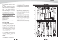
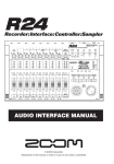
BLOCK DIAGRAM
Don't use solvents such as benzol, alcohol,
or other fluids with very strong volatility and
flammability for cleaning the apparatus body.
Clean only with dry cloth.
Do not use this apparatus near water.
Install in accordance with the manufacture-r's
instructions. Do not install near any heat
sources such as radiators, heat registers,
stoves, or other apparatus (including amplifiers) that produce heat. Do not block
any ventilation openings.
Servicing
Refer all servicing to qualified personnel. To
reduce the risk of electric shock, do not
perform any servicing other than that
contained in the operating instructions unless
you are qualified to do so .
No naked flame sources, such as lighted
candles, should be placed on the apparatus.
Servicing is required when the apparatus has
been damaged in any way , such as power
supply cord or plug is damaged , liquid has
been spilled or objects have fallen into the
apparatus, the apparatus has been exposed
to rain or moisture , does not operate
normally, or has been dropped.
IMPORTANT SAFETY INSTRUCTIONS
Read these instructions.
Follow all instructions.
Keep these instructions.
Heed all warnings.
Only use attachments/accessories specified by the manufacturer.
The mains plug is used as the disconnect device,
the disconnect device shall remain readily
operable.
Power Cord and Plug
Do not defeat the safety purpose of the
polarized or grounding type plug.
A polarized plug has two blades with
one wider than the other. A grounding
type plug has two blades and a third
grounding prong. The wide blade or the
third prong are provided for your safety.
If the provided plug does not fit into your
outlet, consult an electrician for replacement of the obsolete outlet.
Protect the power cord from being walked on or pinched particularly at plugs,
convenience receptacles, and the point
where they exit from the apparatus.
Cleaning
When the apparatus needs a cleaning, you
can blow off dust from the apparatus with
2
23
12 CHANNEL MIXING CONSOLE
INTRODUCTION
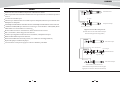
PRESET LIST ( for 12 CHANNEL with digital effect )
Thank you choosing for purchasing 12 Channel Mixing Console. This is a professional
No.
Preset
Description
Parameter
compact mixer to give you great quality and better reliability than ever before You will get
the smooth, accurate more natural and open sound from this apparatus. and it is really ideal
00~09
Echo
Reproduce the sound in input on the
output after a lapse of time or delay.
10~19
Echo+Verb
Echo with Room effect.
Tremolo
Amplitude modulation of the signal.
30~39
Plate
Simulate the transducers sound like
classic bright vocal plate.
Decay time:0.9s~3.6s
40~49
Chorus
Recreate the illusion of more than one
instrument from a single instrument sound.
Rate : 0.92Hz ~1.72Hz
50~59
Vocal
Simulate a small space with slight
decay time.
Rev. decay time: 0.8~0.9s
Pre-delay: 0~45ms
Rotary
Simulate the sound effect achieved by
Modulation depth : 20%~80%
rotating horn speakers and a bass cylinder.
Small Room
Simulate a bright studio room.
80~89
Flanger+Verb
Simulate to play with another person
carrying out same the notes on the same
instrument and reverb.
Decay time : 1.5~2.9s
Rate : 0.8Hz ~2.52Hz
90~99
Large Hall
Simulate a large acoustic space of the
sound.Decay time : 3.6~5.4s
Pre-delay : 23~55ms
Delay Time : 145~205ms
for gigs, recording and fixed PA installations.
Delay Time : 208~650ms
Decay time : 1.7~2.1s
The 12 Channel Mixing Console is packed with features that can not be found in other
consoles of its size: 4mono (provided with ultra low noise microphone pre amplifiers and
Phantom Power at +48 Volt ) and 4 stereo input channels and each of them is provided with
20~29
Rate : 0.6 Hz~5 Hz
a 3-band equalizer for HI, MID and LOW controls, as well as 2 auxiliary control; highly
accurate 12-segment bar graph meters and 2-track inputs assignable to main mix, control
60~69
room/phones Outputs etc..
This unit is very easy to operate but we advise you to go through each section of this manual
carefully. In this way you will get the best out of your 12 Channel Mixing Console.
READY TO START
1) Please check the AC voltage available in your country before connecting your mixer to the
AC socket.
70~79
Decay time : 0.7~2.1s
Pre-delay : 20~45ms
2) Be sure that the main power switch is turned off before connecting the mixer to the AC
socket. Also, you should make sure that all input and output controls are turned down. This
will avoid damage to your speakers and avoid excessive noise.
3) Always turn on the mixer before the power amplifier; turn off the mixer after the power
amplifier.
4) Before connecting and disconnecting the unit from the power source always turn off the unit.
5) Do not use solvents to clean your mixer. A dry and clean cloth will be OK.
22
3
12 CHANNEL MIXING CONSOLE
FEATURES
Ring=Return Signal (Connected together)
To Channel Insert
Ultra-low noise discrete MIC Preamps with +48V Phantom Power.
4 MIC Input Channels with XLRs and balanced Line Inputs and Insert I / O and Compressors
Sleeve=Ground/Screen
control
Low Cut for each MIC Input
Tip=Signal
2 Stereo Input Channels with mono XLRs Input and TRS Jacks;2 Stereo Input Channels with
RCA Jacks and TRS Jacks.
To Tape or FX Input
3-band EQ and Peak LEDs on each MIC channels. 2-band EQ and Peak LEDs on Stereo channels.
1 AUX Sends POST/PRE per channel for monitoring or external effects.1 DFX(AUX) Sends
POST Fader for internal effects or monitoring
Mute and PFL function for each channels, 60mm Fader for level control.
GR1 / 2 and Main L / R bus assign for each channel
Sleeve=Ground/Screen
'Tapped' Connection Direct Output Lead
(Enables the Insert to be used as a Direct Output
while maintaining the channel signal flow)
2-Track Input assignable to Main Mix or Control Room / Headphone Outputs.
Balanced XLR & TRS outputs for Main Mix
Built in 24-bit DSP effect with 100 presets.( for 12CH mixer with digital effects)
Option MP3 player or Bluetooth player.
To Processor Input
Internal switch-mode power supply for maximum flexibility 100-240V.
Sleeve=Ground/Screen
Tip=Send Signal
Tip
To Channel Insert
Sleeve
Ring=Return Signal
Ring
To Processor Output
Y-Stereo lead for insert Connection
(To be used when the processor does not employ a
single jack connection for the In/Out Connections)
4
21
12 CHANNEL MIXING CONSOLE
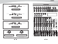
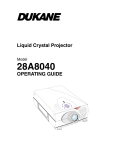
CONTROL ELEMENTS
Ring=Right Signal
Tip
Ring
Sleeve
Strain Clamp
Tip=Left Signal
1
2
3
4
MIC
MIC
MIC
MIC
LINE
LINE
LINE
LINE
INSERT
INSERT
INSERT
INSERT
5/6
7/8
MIC
MIC
9/10 11/12
2TK IN
2TK OUT
MAIN MIX OUTPUT
L
L
R
L
Sleeve=Ground/Screen
R
Use for Headphone, Stereo Return
1/4" Stereo (TRS) Jack Plug
Sleeve
L(MONO)
L(MONO)
R
R
R
LINE 9/10
LINE 11/12 ST RETURNS
CTRL.
GR1 OUT
MAIN MIX
AUX SENDS
FOOT SW
GR2 OUT
L
DFX SENDS
PHONES
L
L
L(MONO)
L
R
R
R
R
R
Tip
Tip=Signal
Strain Clamp
0 MIC
15 LINE
50dB
35dB
0 MIC
15 LINE
LOW CUT
50dB
35dB
0 MIC
15 LINE
LOW CUT
50dB
35dB
0 MIC
15 LINE
LOW CUT
0 MIC
20 LINE
LOW CUT
COMP
COMP
50dB
35dB
40dB
20dB
0 MIC
20 LINE
LOW CUT
COMP
40dB
20dB
LOW CUT
COMP
Sleeve=Ground/Screen
0
10
0
10
0
1
Use for Mono Line In, Mono 1/4"Jack Plugs
0
1/4" Mono (TS) Jack Plug
0
EQ
4
0
EQ
5/6
0
EQ
7/8
0
EQ
9/10
0
EQ
11/12
0
EQ
EQ
HI
HI
HI
HI
HI
HI
12KHz
12KHz
12KHz
12KHz
12KHz
12KHz
12KHz
12KHz
15
15
15
MID
MID
MID
0
0
LOW
0
LOW
80Hz
MID
80Hz
80Hz
0
LOW
80Hz
10
0
LOW
80Hz
80Hz
7
0
LOW
4
TO AUX
LOW
80Hz
PWR
CLIP
TO MAIN
15
PROGRAM (PUSH)
0
LOW
ST RETURNS
0
88
2.5KHz
15
15
0
LOW
48V
DIGITAL
EFFECTS
15
15
MID
2.5KHz
15
15
15
15
0
2.5KHz
15
15
15
15
0
2.5KHz
15
15
15
15
0
2.5KHz
0
15
15
0
15
15
Ring=Return Signal
15
15
0
MID
Tip
Ring
0
EQ
2.5KHz
Sleeve
10
HI
0
15
0
3
HI
15
15
10
2
2
80Hz
0
15
15
15
15
15
15
15
15
15
15
15
15
15
15
15
15
15
2
AUX
AUX
AUX
AUX
AUX
AUX
AUX
AUX
0
FX TO
AUX
0
SENDS
4
AUX
7
Strain Clamp
Tip=Send Signal
15
POST
PRE
Sleeve=Ground/Screen
15
POST
PRE
15
POST
PRE
15
POST
PRE
15
POST
PRE
15
POST
PRE
15
POST
PRE
15
POST
PRE
15
20
DFX
DFX
DFX
DFX
DFX
DFX
DFX
DFX
POST
POST
POST
POST
POST
POST
POST
POST
15
15
PAN
15
PAN
15
PAN
15
PAN
15
BAL
15
BAL
15
BAL
BAL
Use for Pre-Gain Channel Inserts
L/1
R/2
L/1
R/2
L/1
R/2
L/1
R/2
L/1
R/2
L/1
R/2
L/1
R/2
L/1
10
15
00
10
20
30
40
50
60
70
80
90
09 Echo
19 Echo Verb
29 Tremolo
39 Plate
49 Chorus
59 Vocal
69 Rotary
79 Small Room
89 Flange Verb
99 Large Hall
0
DFX
0
0
15
CTRL./PHONES
MUTE
MUTE
MUTE
MUTE
MUTE
MUTE
MUTE
PFL
PFL
PFL
PFL
PFL
PFL
PFL
PFL
PEAK
R
15
15
R/2
MUTE
30
L
OUTPUT LEVEL
2TK IN/MP3
MUTE
1/4" Stereo (TRS) Jack Plug
PEAK
2=Hot(+)
2
1
3
2=Hot(+)
1=Ground/Screen
2
1
3
3=Cold(-)
3=Cold(-)
Use for Balanced Mic Inputs
(For unbalanced use, connect pin 1 to 3)
Use for Main output
(For unbalanced use, leave pin 3 unconnected)
3-pin XLR Male Plug
3-pin XLR Line Socket
(seen from soldering side)
(seen from soldering side)
20
PEAK
PEAK
PEAK
PEAK
PEAK
10
10
10
10
10
10
10
dB
dB
dB
dB
dB
dB
dB
5
5
5
5
5
5
5
5
GR1 2
5
0
GR1 2
5
L R
0
GR1 2
5
L R
0
GR1 2
5
L R
0
GR1 2
5
L R
0
GR1 2
5
L R
0
GR1 2
5
L R
MAIN
GR 1-2
TO CTRL.
TO MAIN
PEAK
10
dB
0
1=Ground/Screen
PEAK
PFL
GR1 2
0
5
L R
10
10
10
dB
dB
dB
5
5
5
0
0
5
0
5
L R
5
L R
10
10
10
10
10
10
10
10
10
10
10
15
15
15
15
15
15
15
15
15
15
15
20
20
20
20
20
20
20
20
20
20
20
30
40
60
30
40
60
30
40
60
30
40
60
30
40
60
30
40
60
30
40
60
30
40
60
30
40
60
30
40
60
30
40
60
GR 1-2
MAIN
MIX
1
2
3
4
5/6
7/8
5
9/10
11/12
DFX
12 CHANNEL MIXING CONSOLE
1
2
3
4
5/6
7/8
MIC
MIC
MIC
MIC
MIC
MIC
LINE
LINE
LINE
LINE
L(MONO)
L(MONO)
9/10 11/12
2TK IN
2TK OUT
0 MIC
15 LINE
50dB
35dB
INSERT
0 MIC
15 LINE
LOW CUT
50dB
35dB
0
10
0
0
50dB
35dB
0 MIC
20 LINE
LOW CUT
10
0
0
R
40dB
20dB
0 MIC
20 LINE
LOW CUT
LINE 11/12 ST RETURNS
L
L
L(MONO)
L
R
R
R
R
0
EQ
5/6
0
EQ
7/8
0
EQ
9/10
0
EQ
0
EQ
HI
HI
HI
HI
12KHz
12KHz
12KHz
12KHz
15
15
0
15
15
0
0
MID
MID
MID
MID
2.5KHz
2.5KHz
2.5KHz
2.5KHz
15
0
15
15
0
0
LOW
80Hz
10
80Hz
7
15
0
LOW
0
LOW
80Hz
PWR
CLIP
TO MAIN
MID
2.5KHz
0
LOW
48V
ST RETURNS
0
15
15
15
15
0
LOW
80Hz
15
15
0
LOW
80Hz
15
15
15
15
0
MID
15
15
15
2.5KHz
15
0
LOW
80Hz
4
HOW
80Hz
TO AUX
2
80Hz
0
15
15
15
15
15
15
15
15
15
15
15
15
15
15
15
15
15
2
AUX 1
1
AUX 1
AUX 1
AUX 1
AUX 1
AUX 1
AUX 1
AUX
0
SENDS
4
AUX1
7
15
POST
PRE
15
POST
PRE
2
15
POST
PRE
2
15
POST
PRE
2
POST
15
POST
PRE
2
POST
15
POST
PRE
2
POST
15
POST
PRE
2
POST
15
POST
PRE
2
POST
15
20
0
2
POST
10
POST
AUX2
POST
30
L
R
OUTPUT LEVEL
15
15
PAN
L/1
R/2
15
PAN
L/1
R/2
15
PAN
L/1
R/2
15
PAN
L/1
R/2
15
BAL
L/1
R/2
15
BAL
L/1
R/2
15
BAL
L/1
R/2
15
BAL
L/1
0
0
15
R/2
15
CTRL./PHONES
MUTE
MUTE
MUTE
MUTE
MUTE
MUTE
MUTE
MUTE
PFL
PFL
PFL
PFL
PFL
PFL
PFL
PFL
PEAK
PEAK
PEAK
PEAK
PEAK
PEAK
PEAK
10
10
10
10
10
10
10
dB
dB
dB
dB
dB
dB
dB
5
5
5
5
5
5
5
5
0
5
0
GR1 2
5
L R
0
GR1 2
5
L R
0
GR1 2
5
L R
0
GR1 2
5
L R
0
GR1 2
5
L R
0
GR1 2
5
L R
MAIN
GR 1-2
2TK IN/MP3
TO CTRL.
TO MAIN
PEAK
10
dB
GR1 2
GR1 2
0
5
L R
10
10
dB
dB
5
5
0
0
5
L R
5
L R
10
10
10
10
10
10
10
10
10
10
15
15
15
15
15
15
15
15
15
15
20
20
20
20
20
20
20
20
20
20
30
40
60
30
40
60
30
40
60
30
40
60
30
40
60
30
40
60
30
40
60
30
40
60
30
40
60
30
40
60
GR 1-2
MAIN
MIX
1
2
3
ON
ON
AC POWER
+48V
48
49
50
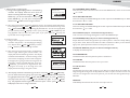
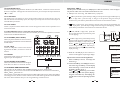
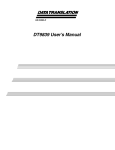
50. PHANTOM ON / OFF
This switch will apply +48V phantom power only to the 6XLR inputs sockets. When these
XLR sockets are connected with devices that do not require phantom power, please make
sure the phantom power is turned off. Otherwise, this may damage the device and mixer.
R
EQ
HI
12KHz
0
PHONES
AC INPUT
100-240V 50/60Hz
Fuse:T1.6AL AC250V
Rated Power: 40W
11/12
HI
0
AUX2 SENDS
49. POWER ON / OFF
This button is used to turn the Main Power on and off.
INSTALLATION AND CONNECTION
4
12KHz
15
L
GR2 OUT
Use only with a 250V fuse
10
HI
15
AUX1 SENDS
MAIN MIX
LOW CUT
12KHz
15
GR1 OUT
40dB
20dB
HI
15
CTRL.
COMP
3
EQ
R
R
LINE 9/10
12KHz
15
15
0 MIC
15 LINE
COMP
2
EQ
INSERT
LOW CUT
1
0
50dB
35dB
COMP
10
15
0 MIC
15 LINE
LOW CUT
COMP
0
INSERT
R
L
R
INSERT
48. AC INLET WITH FUSE HOLDER
Use it to connect your mixer to the main AC with the
supplied AC cord.
MAIN MIX OUTPUT
L
L
4
5/6
7/8
9/10
11/12
Ok, you have got to this point and you are now in the position to successfully operate your 8/10
Channel Mixing Console. However, we advise you to read carefully the following section to be
the real master of your own mixer. Not paying enough attention to the input signal level, to the
routing of the signal and the assignment of the signal will result in unwanted distortion, a corrupted
signal or no sound at all. So you should follow these procedures for every single channel:
Before connecting mics or instruments, make sure that the power of all your systems
components including the mixer is turned off. Also, make sure that all input and output controls
of your mixer are turned down. This will avoid damage to your speakers and avoid excessive
noise.
Properly connect all external devices such as mics, power amplifiers, speakers, effect processor
etc.
Now, turn on the power of any peripheral devices, then power up the mixer.
Note: the power amplifier or powered monitors shall be turned on after the mixer and turned
off before the mixer.
Set the output level of your mixer or the connected power amplifier at no more than 75%.
Set the CONTROL ROOM/PHONE level at no more than 50%.
Position HI, MID and LOW EQ controls on middle position.
Position panoramic (PAN/BAL) control on center position.
While speaking into the mic (or playing the instrument ), adjust the channel Level control so
that the PEAK LED will blink occasionally, in this way you will maintain good headroom and
idea dynamic range.
You can shape the tone of each channel by adjusting the equalizer controls as desired.
Now repeat the same sequence for all input channels. The main LED could move up into the
red section, in this case yo can adjust the overall output level through the MAIN MIX control.
Some Final Tips on Wiring Configuration
You can connect unbalanced equipment to balanced inputs and outputs. Simply follow these
schematics.
6
19
12 CHANNEL MIXING CONSOLE
e- VOL+
Press VOL+ key to increase volume during Power on state.
The following features will be applied to both the 12 channe1s and 12 channels with
digital effects. In case where different features need to be described for each other,
the unit 12 channels with digital effects will be descried first, followed by the unit 12
fPLAY/PAUSE
In play state, press
PLAY / PAUSE key to pause the player. In pause state, press
PAUSE key to start playing.
channels feature in brackets.
PLAY /
g- PAIR
Press this key and hold for 2-3 seconds, the player will change to matching state. In this sate,
the two LEDs alternately flash quickly, and you can u se your mobile phone, tablet or
PC Bluetooth adapter to find devices, BT-2.1. If your device's Bluetooth version lower than
2.0, you should enter the password "0000". If your device's Bluetooth version higher than 2.0,
you do not need to enter a password.
1
1
4
3
3
2
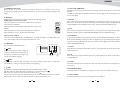
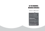
2. LINE INPUT JACKS (CHs 1 to 4)
These are balanced TRS phone-jack line
inputs. You can connect either balanced
or unbalanced phone plugs to these jacks.
5
6
3. LINE INPUT JACKS (CHs 5/6 to
47. Optional USB interface
This section can be selected and installed according to user' s
requirement.
The USB interface provides a digital audio connections to
PC / MAC.
0 MIC
15 LINE
11/12)
These are unbalanced phone-jack stereo
line inputs.
USB USE
With this interface you can use the unit like soundcard for recording at 16 bit / 44.1 kHz and
play back audio file (wave, aiff, mp3 etc.) With Windows and Macintosh computers. Use the
computer built in audio recorder or use dedicated Digital Audio Workstation software (DAW)
to record and play back CD-quality audio within your computer. For connection the unit to
computer. We suggested a standard A MALE / B MALE USB cable , and we wish that you do
not use hubs and other extenders, that often cause glitches and other problems. The USB
port sends the MAIN MIX left and right signals to the computer.
The USB port receives a stereo audio stream from the computer and assigns it to the 2-TRACK
INPUT left and right channels of your mixer.
NOTE: If a device is connected to the 2-TRACK INPUT, the signal from this device is merged
with the signal from the computer.
To ensure that the unit is recognized correctly by your computer, always turn the mixer on a
few seconds before inserting the USB cable into the computer. When powering up both your
computer and the unit, turn on the mixer first and the computer second.
When powering down your computer and the unit, turn off the computer first . Wait to turn
off the mixer until the computer has completed the shut down process.
50dB
35dB
0 MIC
20 LINE
40dB
20dB
7
LOW CUT
LOW CUT
COMP
8
0
47
18
1. MIC INPUT JACKS (CHs 1 to 7/8)
These are balanced XLR-type microphone
input jacks
10
4. LINE INPUT JACKS (CH 9/10 to 11/12)
These are unbalanced stereo RCA pin jacks.
NOTE: Where an input channel provides both a MIC input jack and a LINE input jack, or a
LINE input jack and an RCA pin jack, you can use either jack but not both at the same time.
Please connect to only one jack on each channel.
5. INSERT JACKS
Each of these jacks provides an insert point between the equalizer and level control of
the corresponding input channel, The INSERT jacks can be used to independently connect
devices such as graphic equalizers, compressors, or noise filters into the corresponding
channels. These are TRS phone jacks that carry both the send and return signal.
6. GAIN CONTROL
Adjusts the input signal level. To achieve the best balance between S / N and dynamic range,
adjust the level so that the peak LED indicator lights occasionally only on the highest input
transients. For mono channel the MIC input adjustment range of the Gain is 0 to 50dB and the
sensitivity of line input is +15 to -35dB; For stereo channel the MIC adjustment range of the
Gain is 0 to 40dB and the sensitivity of line input is +20 to -20dB.
7
12 CHANNEL MIXING CONSOLE
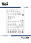
7. LOW CUT
By pressing this button you will activate a 75Hz low frequency filter with a slope of 18dB per
octave. You can use this facility to reduce the hum noise infected by the mains power supply.
Or the stage rumble while using a microphone.
8.COMP CONTROL
Adjust the amount of compression applied to the channel. Turn the knob to the right to increase
the compression ration and the output gain will automatically adjusted. The result is smoother,
more even dynamics because louder signals are attenuated which the overall level is boosted.
9. EQUALIZER
Hi
This is the treble control. You can use it to get rid of high
frequency noises or to boost the sound of cymbals or the high
harmonics of the human voice. The gain range goes from -15dB
to +15dB with a center frequency of 12kHz.
ePLAY/PAUSE
In play state, press
PLAY / PAUSE key to pause the player. In pause state, press
PAUSEkey to start playing.
PLAY /
f - REC
In power on state, press this key, it will go to the recording preparation state. Press REC again
to start recording. Any other operations are not available in recording state until press POWER
to stop recording;
g - POWER(Push & Hold)
When the unit is off, press this key and hold for about 2 or 3 seconds to turn on the power
supply of player. Repeat the above operation, you can turn off the power supply of the player.
1
0
EQ
h- DISPLAY:
All the USB player information are monitored through this sexy & magic display.
HI
12KHz
15
15
0
MID
2.5KHz
MID
This is the mid range control. It can affect most fundamental
frequencies of all musical instruments and human voice. An
attentive use of this control will give you a very wide panorama
of sound effects. The range goes from -15dB to +15 dB and the
center frequency of 2.5kHz.
0
LOW
80Hz
15
15
AUX
15
POST
PRE
POST
12
15
PAN
13
L/1
R/2
MUTE
10. AUX
These controls are used to adjust the level of the signal sent to
AUX buses, and their adjustable range is from - to +15dB .
14
a-Display
Bluetooth Audio Interface
These two LEDs use to display different
working state:
1). For the first time that module power on,
SBT-2.1
it is on stand by state, and the right LED
flashes twice about 2 seconds once.
2). Matching state, two LED's alternately flash quickly.
3). After connected the device, the right LED lighted on constantly.
VOL-
VOL+
PAIR
(d) (e) (g)
PFL
15
PEAK
16
10
11. PRE/POST
Each channel is equipped with the PRE/POST button, pressing
this button the signal can be assigned to PRE / POST-FADER.
Option Four - Bluetooth Version 2.1
C an be paired with mobile phones, tablets or PC Bluetooth adapter to play stereo audio with
two LED status indicator.
(a)
(b) (c) ( f )
10
11
DFX
Low
This is bass control . it is used to boost male voice, kick drum
or bass guitar. The gain range goes from -15dB to +15dB with
a center frequency of 80Hz.
9
15
15
dB
17
5
0
bPRE
Press this key, it will go to the previous track and start playing.
GR1 2
18
5
L R
10
cNEXT
Press this key, it will go to the next track and start playing.
15
12. DFX / POST
These controls are used to adjust the level of the POST FADER
signal sent to DFX (AUX) SENDS output, which can be used
for monitor application and effects & sound processors input.
8
20
30
40
60
19
1
d- VOLPress VOL- key to decrease volume during Power on state. The default factory setting
is maximum.
17
12 CHANNEL MIXING CONSOLE
g- POWER(Push & Hold)
When the unit is off, press this key and hold for about 2 or 3 seconds to turn on the
power supply of player. Repeat the above operation, you can turn off the power supply of the
player.
h- DISPLAY:
All MP3 player information are monitored via this sexy & magic display.
NOTE: basic interface instruction
When the player isn't connected to a USB memory equipment,
the interface is as follows:
When the player is searching for USB tracks, the interface is as
follows:
When the player is in pause state, the interface is as follows:
When the player is in use, the interface is as follows:
14. MUTE
Each channel is equipped with the MUTE button , pressing this button is equal to turning the
fader down, which can mute the corresponding channel output except for the PRE AUX sends,
channel INSERT send and SOLO (in PFL mode), and the MUTE LED will illuminate.
15. PFL
Each channel is equipped with the PFL button , pressing this button which the corresponding
AUX send will be routed to CTRL ROOM/PHONES outputs and METER display.
Option Three - SMP-R
The file system of USB memory for USB players is FAT16 and FAT32, and these players can
only decode MP3. It has 7 rank subordinate folders at most.
a- USB PORT
For connecting with USB memory.
(h)
SMP-R
17. GR1-2
Each channel is equipped with the GR1-2 button , pressing this button which can send the signal
to GR1-2 mix bus.
REC
(e) ( f )
POWER
(Push & Hold)
(g)
cNEXT
In pause state, press this key, it will go to next track and keep in pause state. In play state,
press this key, it will go to the next track and start playing.
dRPT
Press this key, the player will change between the following four modes:
REP ALL means to repeat all tracks in the memory, mark on the screen is
REP1 means to repeat one track, the mark on the screen is
Play in order means to play the tracks according to the order, the mark on the screen is blank.
Random play means to play the tracks at random, the mark on the screen is A.
16
16. PEAK LED
The peak level of the post-EQ signal is detected, and the PEAK indicator lights red when the
level reaches 3dB below clipping. For XLR-equipped stereo input channels, both the post-EQ
and post-mic-amp peak levels are detected, and the indicator lights red if either of these levels
reaches 3 dB below clipping.
(b) (a) (c) (d)
USB PLAYER
bPRE
In pause state, press this key, it will go to
previous track and keep in pause state. In
play state, press this key, it will go to the
previous track &start playing.
13. PAN / BAL CONTROL.
The PAN control determines the stereo positioning of the channel signal on the stereo L and
R buses.
The BAL control knob sets the balance between left and right channels. Signal input through
the stereo L/R bus.
18. L-R
Each channel is equipped with the L-R button , pressing this button which can send the signal
to MAIN MIX bus.
19. LEVEL
This fader will adjust the overall level of this channel and set the amount of signal sent to the
main output.
20. MAIN MIX LEVEL
This fader is used to set the amount of signal sent to the main mix output and tape out.
21. GR1-2 LEVEL
This fader is used to set the amount of signal sent to the GR1-2
9
12 CHANNEL MIXING CONSOLE
22. DFX LEVEL (only for 12 channel with digital effects)
This fader is used to set the amount of signal sent to the internal digital effect return to MAIN
MIX bus.
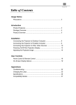
23.2-TRACK SIGNAL PATH
If you push down the 2 TRACK SIGNAL PATH knob, the 2 TRACK IN signal will be routed into
the CONTROL ROOM output. Then push the knob again, the 2TRACK IN signal will be
routed into the MAIN MIX output..
31
24. 2-TK IN/MP3
This control is used to adjust the volume
from - to +10dB.
25. MAIN MIX/GR1-2
If you push down the MAIN MIX/GR1-2
button, the signal from GR1-2 will be
routed into the CONTROL ROOM
output. Then push the knob again, the
signal from MAIN MIX will be routed
into the CONTROL ROOM output
(Note, once the PFL button was pressed,
the signal on CONTROL ROOM will not
be affected by pressing the MAIN MIX/
GR1-2 button)
26. PHONES/CONTROL ROOM
This control is used to adjust the signal
present at the Phones / control room
output, which can be varied from - to
+15 dB.
35
36
48V
PWR
e )-Folder List:
See the Fig 3, the display shows MP3 files folders names. Use
PRE/
NEXT key to
scan, press
PLAY / PAUSE key, you'll enter into corresponding folder. In order to
return to Fig5 interface, you just need to press the STOP key.
Option Two - SMP-T
The file system of USB memory for USB players is FAT16 and FAT32, and these players can
only decode MP3. It has 7 rank subordinate folders at most.
(h)
DIGITAL
EFFECTS
ST RETURNS
0
88
34
10
7
15
PROGRAM (PUSH)
0
4
SMP-T
TO AUX
2
33
0
15
27
2
30
0
FX TO
AUX
0
SENDS
4
AUX
32
7
15
10
15
29
09 Echo
19 Echo Verb
29 Tremolo
39 Plate
49 Chorus
59 Vocal
69 Rotary
79 Small Room
89 Flange Verb
99 Large Hall
0
DFX
30
L
R
OUTPUT LEVEL
0
24
2TK IN/MP3
MUTE
23
PFL
MAIN
GR 1-2
TO CTRL.
TO MAIN
25
27. OUTPUT LEVEL
This stereo 12 segments LED meter
will be indicate the level of overall
output signal.
10
10
10
dB
dB
dB
5
5
5
0
0
0
5
5
10
10
10
5
15
15
15
20
20
20
30
40
60
30
40
60
30
40
60
GR 1-2
MAIN
MIX
L R
DFX
22
cNEXT
In pause state, press this key, it will go to next track and keep in pause state. In play state, press
this key, it will go to the next track and start playing.
15
CTRL./PHONES
PEAK
28
15
0
15
26
10
POWER
(Push & Hold)
bPRE
(g)
(e) ( f )
In pause state, press this key, it will
go to previous track and keep in pause state. In play state, press this key, it will go to the previous
track & start playing.
20
00
10
20
30
40
50
60
70
80
90
28. DFX (AUX2)
These control is used to determine the
internal DSP module levels and DFX
sends output, which can be varied from
- to +15 dB.
USB PLAYER
a- USB PORT
For connecting with USB memory.
CLIP
TO MAIN
(b) (a) (c) (d)
21
20
dRPT
Press this key, the player will change between the following four modes:
REP ALL means to repeat all tracks in the memory, mark on the screen is
REP1 means to repeat one track, the mark on the screen is
Play in order means to play the tracks according to the order, the mark on the screen is blank.
Random play means to play the tracks at random, the mark on the screen is A.
ePLAY/PAUSE
In play state, press
PLAY / PAUSE key to pause the player. In pause state, press
PAUSEkey to start playing.
PLAY /
f- STOP
In play state, press this key to stop playing and all the songs in USB memory will appear on the
display; In stop state, press STOP /
PRE/
NEXT keys again to go to first song and the
player will keep in pause state, then press
PLAY/PAUSE key to play the song.
15
12 CHANNEL MIXING CONSOLE
c- "Playing" mode - single song play
1). In Fig 2, selecting the Playing mode to recall following
interface. This display shows the name of all the
folders containing MP3 files. Using the
PRE /
NEXT keys, you can scan the folders, then press
PLAY / PAUSE key, you will open corresponding
folders. Press STOP to return to Fig 2 interface.
[ 002 ] 00 : 05
01. Plena pop 01.mp
02. Pop 02.mp3
03. Plena pop 03.mp
Fig 4
2). After opening the folder, the display will show as Fig 3. This display shows MP3 file list,
and scrolling list using
PRE /
NEXT keys you can choose the desired song. Press
the PLAY / PAUSE key, the selected song playback will start. In order to stop playback,
you just need to press the stop key. Then, if you press the
PLAY / PAUSE key, the
song playback will start from the pause point, if you press again the stop key, the
system will return to Fig 3 interface.
d)-"Program" mode
1). In Fig 2, select "Program" to enter into the following
interface: " Play list Set ": Set the playing list."Playing
List": Play list. Press
PRE/
NEXT key to select,
press STOP key to return the Fig2 interface.
2). After entering into the "Play List Set", the display will
show as Fig3. Selecting the desired folder, the
display will show the following interface. The display
will show all the MP3 files, the selected song will be
inserted into the playing list and a mark will appear.
Press again you're going to delete the song from the
playing list, and the mark will disappear. Press the
STOP key, you will return to Fig 2 interface. The
playing list can accept up to 20 songs, and it will
display the list according to song insert order.
3 ). The display will show the following interface. Press the
Fig 5
30. ST RETURNS TO AUX
This control assign the ST RETURN signals to their respective AUX SEND outputs. Which can
be varied from - to +15 dB.
31. ST RETURNS TO MAIN
This control assign the ST RETURN signals to their respective MAIN MIX outputs. Which can
be varied from - to +15 dB.
32. FX TO AUX (only for 12 channel with digital effects)
This control is used to assign the signal from FX to AUX SEND output.
33. PROGRAM(PUSH) (only for 12 channel with digital effects)
Adjust this knob to select the right effect you wish to perform. There are totally 100 options
for you: Echo, Vocal, Plate and versatile two-effect combination. When you are satisfied the
right preset, please push this knob to store this preset you want.
34. DIGITAL EFFECTS (only for 12 channel with digital effects)
It displays the selected preset.
Fig 6
[ . ] 00 : 20
01. lena pop 02.mp3
02. Plena pop 06.mp
03. Plena pop 04.mp
Fig 7
PRE /
NEXT key,
you can select the starting song, then press the PLAY/PAUSE key, the selected
song playback will start. Press PLAY / PAUSE key again, or press STOP key,
the play back will stop. Press
PLAY / PAUSE key again, or press STOP
key, the playback will start again from the same point. Twice press STOP, the
USB player will return to Fig 3 interface.
14
29. AUX SENDS (AUX1 SENDS)
This control is used to determine the master AUX SEND levels, which can be varied from
to +15 dB.
35. PHANTOM LED
This LED indicates when the phantom power is switched on.
36. PWR LED
This LED indicates when the power is on in your mixer.
37. 2TK IN / OUT
TAPE IN
Use the Tape input if you wish to listen to your Mix from a Taper Recorder or DAT. You can
assign the signal coming from the Tape Recorder either to a pair of studio monitor using the
control room assignment on the front panel or you can also send the signal directly to the
Main Mix.
TAPE OUT
These RCA jacks will route the main mix into a tape recorder.
11
12 CHANNEL MIXING CONSOLE
38. MAIN MIX OUTPUT
The stereo output is supplied both XLR and 1/4" TRS sockets, which are used to send the
audio to an amplifier. Through the main mix level control, you can adjust the output level from
- to +10dB.
Option One - SMP-S
The file system of USB memory for USB players is FAT16 and FAT32, and these players can
only decode MP3. It has 7 rank subordinate folders at most.
a - USB port: For connecting with USB memory equipment.
39. ST RETURNS
Use these stereo 1/4" sockets to return the sound of an effect unit to the main mix. You can
also use them as extra auxiliary inputs, but they are primarily used to connect the output of
external effect processors.
b-
PRE: In pause state, press this key, it will go to the previous song and still keep in pause
state; In play state, press this key, it will go to the previous song and start playing;
Furthermore, press this key and hold for a few seconds to decrease the volume.
40. CTRL-ROOM
These 1/4" phone sockets will be used to send the signal to studio monitor speakers or to
a second set of PA.
c-
NEXT: In pause state, press this key it will go to the next song and still keep in pause
state; In play state, press this key it will go to the next song and start playing; Furthermore
press this key and hold for a few seconds to increase the volume.
41. FOOT SWITCH (only for 12 channel with digital effects)
This socket is used to connect external foot switch for your convenient operation, it has the
same function as DFX MUTE button.
41
37
38
d-
PLAY / PAUSE: In play state, press this
key to pause the player; In pause state, press
to start playing.
42. AUX SENDS (AUX1 SENDS)
These 1/4" phone sockets are used to send out
the signal from the AUX bus to external devices
such as effects.
e-
2TK IN
2TK OUT
MAIN MIX OUTPUT
L
R
L
R
43. GR1/2 OUT
These 1/4" TRS jack are used to send out the
signal from the GR 1 / 2 mix bus to external
devices.
ST RETURNS
CTRL.
GR1 OUT
MAIN MIX
AUX SENDS
FOOT SW
L(MONO)
L
GR2 OUT
L
DFX SENDS
PHONES
R
44. PHONES
This socket will be used to send out the mix
signal to a pair of headphones.
39
f- DISPLAY: All USB player information are
monitored through this sexy & magic display.
R
R
40
43
CN6
45
42
44
CN12
45. DFX SENDS (AUX2 SENDS)
These 1/4" sockets are used to send the signal
from DFX mix buses to external devices .
46
46. OPTIONAL MODULES SECTION
This section can be selected and installed according to user's requirement.
Opening the cover and connect the module with MIXER CN6. the module include SMP-R
SMP-S SMP-T Bluetooth-2.1.
The signal for module playback can be assigned to Main Mix by 2TK routing. when using SMP-R
recording function, the Cn12 need to be connected which the signal come from the Main
Mix. After above finished then you can using following module function:
12
STOP: In play state, press this key to stop
playing and all the songs in USB memory will
appear on the display ; In stop state, press
STOP /
PRE /
NEXT keys again to go
to first song and the player will keep in
pause state, then press
PLAY/ PAUSE key
to play the song.
Operation Instruction for Song Module
a- When no USB key inserted, the display will
show as Fig. 1
b- Inserted the USB key, the USB player starts to
search the songs in USB key, and the display
shows "Searching". At the end of the search,
the display will show as Fig. 2.
Using
PRE /
NEXT keys, you can select
one of following three menu options ("Playing",
"Program" and "Folder List"). Press Playing, the
unit will enter into the corresponding operation
mode.
13
(f)
(d) (b) (a)
(c) (e)
USB PLAYER
SMP-S
INSERT USB KEY
Fig 1
MENU:
PLAYING
PROGRAM
FOLDER LIST
Fig 2
FOLDER:
classic music
jazz music
pop music
Fig 3