1
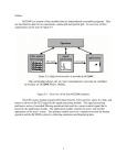
Si3462-EVB 3. Connectors and Switches The Si3462-EVB is equipped with two banana jacks and an optional third banana jack on one side and two RJ-45 connectors on the other side. Figure 2. Placement of Connectors and Switches The board receives power through the banana jacks: J1 GND +50 V nominal input (+45 V to +57 V) for PoE; +54 V nominal input (+51 V to +57 V) for PoE+ J3 Optional banana jack: +3.3 V input An optional onboard +3.3 V shunt regulator generates the supply voltage for the Si3462 from the +50 V input voltage. The +3.3 V supply voltage may also be provided by an external source through the optional banana jack if higher efficiency is desired. In this case, the regulator and its associated resistors (including the series resistors) should be removed. J2 BLACK banana jack: RED banana jack: The RJ-45 Ethernet connectors: J7 ETHERNET IN PoE Reset pushbutton: J8 input output SW1 Mode setting DIP switch: SW2 These switches set the operating mode according to Table 2 on page 7 including the following: Available power level (4 W, 7 W, 15.4 W, and 30 W) or Endpoint configuration Automatic restart or restart after disconnection modes of operation Midspan Refer to "6.1. Initialization and Operating Mode Configuration" on page 7 for more details. Rev. 1.2 4/12 Copyright © 2012 by Silicon Laboratories Si3462-EVB