1
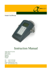
Model DSP-Ex
Portable Dewpoint Meter
Instruction Manual
Alpha Moisture Systems
Alpha House
96 City Road
Bradford
BD8 8ES
England
Tel:
Fax:
Email:
Web:
+44 1274 733100
+44 1274 733200
[email protected]
www.amsystems.co.uk
Model DSP-Ex Automatic Dewpoint Meter
Index
1.
2.
General Description ...............................................................................................................1
Instrument Configuration.......................................................................................................1
2.1
Adjusting Variables .......................................................................................................2
2.2
Selecting Engineering Units ..........................................................................................3
3. Normal Operation ..................................................................................................................5
4. Factory Calibration ................................................................................................................7
5. Batteries .................................................................................................................................7
6. Transit Case ...........................................................................................................................7
7. Hazardous Area Certification ................................................................................................8
1458 DSP-Ex User Manual
Issue 1.0
1. General Description
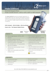
The Model DSP-Ex Automatic Dewpoint Meter is a fully self-contained portable
instrument, specifically designed to measure the moisture content of air or gas on a spotcheck basis.
The instrument is operated with its own internal batteries and requires no external power
source.
The read-out of moisture content is on a dot-matrix LCD, in any one of several selectable
engineering units.
The unique measuring head is designed to keep the sensor dry when the instrument is not in
use, making spot checks a simple and speedy process with minimum air or gas usage.
Model DSP-Ex utilises Alpha Moisture Systems advanced dewSmart sensor which allows
complete interchangeability of sensors and ranges.
The calibrated measuring range is stored within the sensor and is readable from the analyser
display (see page 2, item 2).
Details of normal operation, engineering unit selection, sensor data and configuration of the
instrument are described within this manual.
2. Instrument Configuration
The standard factory settings are such that the instrument will display the moisture content
in °C Dewpoint has the auto switch-off facility activated and the display contrast set at a
mid-point.
The other facilities and information available from the sensor and instrument are determined
by the range of sensor in use, it's calibration data and the hardware of the instrument itself.
To access the available information and change variables use the following procedure:Switch the instrument on by pressing the I/0 key once.
The display will read the word INITIALISING. This is the normal start-up routine during
which the functions of the instrument and integrity of the sensor calibration data are
verified.
The display will then read INSTRUMENT OK. This confirms that all instrument
functions are working normally.
Page - 1
The display will then read CALIBRATION DATA OK. This confirms that normal
communications with the sensor have been established and that the integrity of the
calibration data, held within the sensor, has been verified.
The display will then read the moisture content of the air surrounding the sensor in °C
Dewpoint, (or the equivalent in other engineering units if so selected).
2.1 Adjusting Variables
To read Sensor and Instrument information, change the display contrast and
enable/disable the automatic shut-down facility:a)
Press the keys marked
and
approximately 4 seconds.
together and hold pressed for
The display will read SENSOR INFORMATION.
b)
Press the key marked
once.
The display will show the sensor (probe) serial number.
c)
Press the key marked
once more.
The display will show the calibrated range of the sensor installed.
d)
Press the key marked
once more.
The display will show the calibration date of the sensor installed.
e)
Press the key marked
once more.
The display will show the suggested date of recalibration of the sensor
installed. Normally 12 months after the calibration date.
f)
Press the key marked
once.
The display will show the instrument type and software version
g)
Press the key marked
once more.
The display will show LCD CONTRAST- LIGHTER DARKER
At this point the contrast can be adjusted to the desired level by
either the key marked
to lighten the display or
Page - 2
pressing
to darken the display.
NOTE: The contrast is incremented by the keys and does not scroll by holding the keys
pressed.
When the contrast level is satisfactory, move to step h.
h)
Press the key marked
once more.
The display will show AUTO SHUT DOWN together with the status of this
facility, either ON or OFF.
To put this facility ON (enable) press
To turn it OFF (disable) press
NOTE: When the AUTO SHUT DOWN is ON, the instrument will automatically switch
OFF if no keys are pressed within a period of 5 minutes.
i)
When the variables have been set to the desired positions press the
key marked
.
This fixes the settings within the instrument and on each subsequent start-up
these levels will be maintained.
The display will now be shown °C Dewpoint (or equivalent).
2.2 Selecting Engineering Units
To change the displayed engineering units from ºC Dewpoint to either ºF Dewpoint,
PPM(V), PPB(V), g/m3, lb/MMSCF or PPM(W), use the following procedure:a)
Press the key marked
and hold pressed for approximately 4 seconds.
The display will show the letters SU (select units) in the top right hand corner.
b)
Subsequent presses of the key marked
options of engineering units available.
will scroll the display through the
The order in which the engineering units will appear on the display and their
definitions is as follows:°C DEWPOINT:
The temperature at which Condensation or Frost forms if
the gas is cooled, expressed in degrees centigrade.
It is important to note that the term DEWPOINT is
comonly used to include frost point and all readings below
0ºC are in fact measurements in equilibrium over ice.
°F DEWPOINT:
As above but expressed in degrees Fahrenheit.
Page - 3
PPM(V):
The volume of water vapour per total volume of gas
expressed as parts of water vapour per million parts of
gas.
PPB(V):
As ppm(V) but expressed in parts of water vapour per
billion parts of gas.
This unit is only used in cases where the moisture content
of the gas is less than 1ppm(V) (1000 ppb(V)). At levels
above 1000 ppb(V) the instrument display will show OUT
OF RANGE if switched to the PPB(V) section.
g/m3:
Mass of water per unit volume of gas expressed as grams
of water per standard cubic meter of gas.
lb/MMSCF:
As g/m3 but expressed as pounds of water per million
standard cubic feet of gas.
PPM(W):
Similar to PPM(V) but with reference to mass (weight)
rather than volume. In this case the ratio of weights
change with the molecular weight of the carrier gas.
When the required units of measurement are displayed, press
to enter this
information into the instrument. The instrument will then display the moisture content
in the selected engineering units on each subsequent start-up
If the (enter) key is pressed to select PPM(W) units, the option is then available to select
one of several common gases or a variable setting where the molecular weight of any
other gas can be entered. This option is denoted by the letters SG (Select Gas) which
will be seen in the top right hand corner of the display.
The common gas types installed are AIR, ARGON, NITROGEN, CO2, SF6 & H2.
Scrolling through these options is achieved by pressing the key marked
.
Following the end of the list shown above, the screen will display PPM(W) Mol Wt: X;
where X is any number between 0 and 99.
If PPM(W) is the required unit of measurement and the gas to be measured does not
appear on the installed list, then the molecular weight of this gas should be installed by
pressing the key marked
(1 press = 1 digit).If the key (
which indexes the number (mol weight) between 0 and 99
) is pressed at 99 then the number reverts to 0.
,
When the required gas or molecular weight has been selected, press the key marked
at this point the letters SG will disappear. This installs the selected units into the
instrument programme and the instrument will start-up in these units at every
subsequent 'start-up'.
Page - 4
NOTE. If when the
(enter) key is pressed to select units in PPM(W), the display
already shows the correct gas, simply press
again to confirm this setting.
Other units can be installed by reselecting and storing, using the above procedure.
3. Normal Operation
In order to take moisture content readings of air or gas, having pre-selected the required
units of measurement, use the following procedure:1) Locate the instrument in a convenient position, as close as is practical to the sample
point and move the handle from its carrying position to allow clear operation of the
telescopic measuring head.
NOTE. The position of the handle is adjustable, in 300 steps, by pressing the two black
buttons, one at each pivot point, and manually positioning the handle. Releasing the
buttons allows the handle to lock into the required position.
It is not important which position the instrument is placed in, as it will operate in any
attitude.
2) Switch the instrument ON by pressing the key marked I/0.
NOTE. When the instrument is switched ON, the instrument will go through its initialising
routine and data verification procedures described above. This routine takes
approximately 10 seconds, after which time the instrument will display the moisture
content of the air or gas surrounding the sensor, in whatever engineering units have been
selected. This will happens every time the instrument is switched ON.
3) The sample tube supplied is fitted with a Female Swagelok quick connect coupling, at
one end, for connection to the male connector positioned below and to the left of the
measuring head. To make this connection, simply push the two halves of the connector
together and allow the locking ring to locate. To disconnect this coupling push the
locking ring towards the instrument panel and the two halves will spring apart.
The other end of the sample tube is supplied with a 1/8" NPT male connector which
should be adapted to fit the sample point connector.
NOTE. It is important to note, at this time, that the material used for the sample tube
is critical, especially when measuring very low moisture levels. The ideal material is
stainless steel but this is normally impractical for a portable instrument. Where flexible
tube is to be used, the preferred material is PTFE (Teflon). This offers a reasonable
degree of flexibility and has good resistance to external moisture ingress. The sample
tube supplied with the instrument is ideally suited to this purpose.
4) Open the sample valve, at the sample point, to allow a small flow of air or gas through
the system, at atmospheric pressure. The actual flow is unimportant, as the measuring
sensor is not flow sensitive, but it is suggested that a flow of between 5 and 10 L/min is
an ideal compromise between minimum gas usage and system response speed.
Page - 5
5) Allow the instrument and pipework to purge and then restrict the sample exhaust, from
the instrument, with a finger. This will cause the telescopic section of the measuring
head to extend from the front panel of the instrument under the pressure of air or gas. If
there is insufficient gas pressure to extend the head, grip the outer knurled section of the
head and, while twisting clockwise, gently extend the head by pulling it out from the
front panel, while keeping the sample exhaust blocked.. When the head is fully
extended, remove the finger from the sample exhaust and allow the sample to
flowthrough the measuring head.
6)
The display will indicate the change in moisture content surrounding the sensor.
Observe the display and when there is no further change in reading, the displayed value
is the gas moisture content.
NOTE. If there is any uncertainty as to whether equilibrium has been achieved in the
system (pipework and measuring head), which is necessary to reach an accurate
measurement, a simple test can be carried out as follows:-
a)
b)
After the display has stopped moving, increase the sample flow, slightly.
Observe the display.
i) If the displayed value remains constant the reading is accurate.
ii) If the displayed value begins to fall, the system was insufficiently purged and
water vapour is still outgassing from the internal surfaces of the sample pipe
work or measuring head OR there is a leak at the sample valve or one of the
connections.
It is very important to note that if there is a leak in any part of the system, water vapour
will defuse, from the ambient air, into the sample, even though the gas is flowing out of
the faulty connection.
7)
When the measurement is complete,
a)
Close the measuring head by manually pushing the extended section back
towards the panel front and switch the instrument OFF.
NOTE. Ensure that the measuring head is fully closed. Failure to do so will cause the
internal desiccant to become wet and impair the efficiency of operation of the instrument.
b)
Remove the sample by closing the valve at the tapping point,
c)
Disconnect the sample tube from the instrument and sample point.
This completes the procedure and the instrument can be removed to the next test point
or stored until required again.
NOTE. If the reading taken from the instrument is in 0C or 0F dewpoint, it is important to
remember that this value is at 1 bar A pressure. If the dewpoint is required at any other
pressure, the dewpoint calculator, supplied with the instrument, should be used to calculate
that dewpoint. Instructions for use are printed on the calculator face.
Page - 6
4. Factory Calibration
Comparing the readings given from the instrument with those obtained from a standard,
traceable dewpoint analyser performs factory calibration. The traceability is to the British
Standard Moisture Generator held at the National Physical Laboratory, London. These
comparative results are detailed in the Certificate of Test and Calibration supplied with the
instrument.
5. Batteries
The Model DSP-Ex is powered by 6 x C size batteries.
The typical battery life is in excess of 250 hrs. continuous operation.
The analyser will display, in the top left hand corner of the screen, the letters LB (LOW
BATTERY) when the batteries are to be changed.
At the point when the LB sign is displayed there is approximately 2 hrs. battery life left
before the sign changes to VLB (VERY LOW BATTERY).
At the point when the VLB sign is displayed the batteries will only power the instrument
for a further 30 minutes, at which time the instrument will shut-down totally, and will not
be operational until new batteries are installed.
If the instrument is switched ON after the very low battery automatic shut-down has taken
place it will automatically switch itself OFF again.
Access to the batteries, for replacement purposes, is gained by firstly removing the cover
plate, on the back panel of the instrument, using the Allen Key provided and then
unscrewing the covers from both of the battery holders.
Fit new batteries as shown on label adjacent to the battery holders, replace the covers and
refit the cover plate.
6. Transit Case
(If Supplied)
The transit case is designed specifically to protect the instrument during transportation and
storage.
Access to the analyser, within the case, is achieved by lifting the two catches towards the
carrying handle and moving the latch bars away from the upper section of the locks.
The instrument can be operated either while still installed in the transit case, if the handle is
positioned to allow full movement of the sample chamber, or removed from the case for
ease of positioning near to the sample point.
The sample tube, dewpoint calculator and Allen key to remove the battery carrier cover
plate, are housed in the hinged section inside the lid of the transit case.
Page - 7
The case carrying shoulder strap and keys to lock the case are also housed in the hinged
section inside the lid.
Access to this storage compartment is achieved by pulling the small leather strap,
positioned near the outer edge of the hinged cover, to release the two spring catches, which
secure it.
Ensure that both catches are secure when closing the cover of the compartment to
guarantee secure storage of the items held within.
7. Hazardous Area Certification
See next page
Page - 8