1
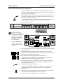
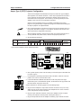
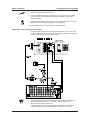
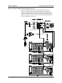
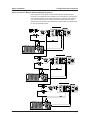
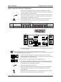
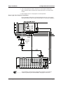
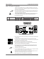
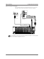
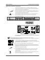
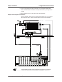
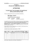
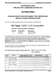
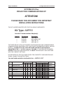
Ampro Installation
Configuration and Connections
SYSTEM 8/10 Plus
PROJECTOR COMMUNICATIONS KIT
ATTENTION!
PLEASE READ THIS DOCUMENT FOR IMPORTANT
INSTALLATION INSTRUCTIONS
THIS KIT HAS BEEN SHIPPED WITH THE FOLLOWING COMPONENTS:
Kit Type: AMPRO
Included Communications Adapter(s):
Quantity
1
1
1
1
Part Number
26-477-01
26-304-01
26-468-01
26-467-01
Description
ADP, UNV, “H”
ADP, AMPRO CRT
ADP, UNV, “B”
ADP, UNV, “A”
THE TABLE BELOW LISTS THE POSSIBLE CONFIGURATION(S) AND CORRESPONDING
COMMUNICATIONS ADAPTER(S) FOR YOUR PROJECTOR MANUFACTURER’S VARIOUS
MODELS. PLEASE NOTE THAT YOUR SWITCHER HAS BEEN CONFIGURED AS
INDICATED BY THE “✔” IN THE “Config as” COLUMN. IF YOUR PROJECTOR MODEL
DIFFERS FROM THIS CONFIGURATION, YOU MUST RECONFIGURE YOUR SWITCHER
WITH THE CORRECT SETTINGS.
PLEASE REFER TO THE FOLLOWING PAGES FOR COMPLETE CONFIGURATION AND
SIGNAL CONNECTION INSTRUCTIONS.
THIS SWITCHER HAS BEEN CONFIGURED FOR:
Config
as
✔
Model
AMPRO CRT
Rotary Switches Cable
SW15 Settings
Comm
RS1 RS2 RS3 RS4 J2/J3 1 2 3 4 5 6 7 8 9 10 Adapter
Ampro LCD-150
0
0
0
B
J2
↓ ↓ ↑ ↓ ↑ ↓ ↓ ↓ ↑ ↓ <none>
Ampro CRT
0
1
5
1
J2
↓ ↓ ↑ ↑ ↓ ↓ ↓ ↓ ↑ ↓ 26-304-01
Ampro 160
0
0
F
F
J2
↓ ↓ ↑ ↓ ↑ ↓ ↓ ↓ ↑ ↓ 26-477-01
Ampro Light Valve
0
1
5
1
J2
↓ ↓ ↑ ↑ ↓ ↓ ↓ ↓ ↑ ↓ 26-468-01
Ampro Alice
0
1
5
1
J2
↓ ↓ ↑ ↓ ↑ ↓ ↓ ↓ ↑ ↓ 26-467-01
Extron • System 8/10 PLUS • User’s Manual • P/N 68-404-01 Rev. A
Ampro Installation
Configuration and Connections
Ampro LCD-150 Projector Configuration
Verify that the System 8/10 PLUS is already configured for the Ampro LCD-150
projector. The general setup is explained on page 3-4 and the switch settings for
the projector are repeated below.
1. Use a small screwdriver to remove the access cover from the System 8/10 PLUS
front panel. See bottom of page 3-3. The label on the back of the access cover
also has the configuration information.
__________ Before changing anything, remove the AC power cord to the System 8/10 PLUS
to verify that the main power is OFF; also turn the projector power OFF.
2. Set the switches as follows:
Config
Model
Rotary Switches Cable
as
RS1 RS2 RS3 RS4 J2/J3
Ampro LCD-150
0
0
0
B
J2
SW15 Settings
1 2
RS5 is for RGB switching
delay. See page 3-4 for
more information on switch
functions.
4
5
6
1
2
3
4
5
6
Comm
7 8
↓ ↓ ↑ ↓ ↑ ↓
ON
_ When connecting the
projector for Video Loopback
(VLB) operation: SW15, DIP
switch #8 must be Down.
See page 3-4 for switch
description, and page 2-10
for VLB operation.
3
9 10
↓ ↓ ↑ ↓
7
8
9
Adapter
<none>
10
SW15 DIP Switch
RS2
RS3
RS5 RS2 RS1
RS4
RS1
RS3 RS4
Configured For:
RS-232
3. Use a grease pencil (or other rub-off marker) to mark the space on the label next
to “Ampro LCD-150”.
4. Locate the switcher’s Address DIP switches on the rear panel, lower right.
Unless this is part of a master/slave system, set #3 and #5 to the up position and
the others down. See illustration to the left.
Use the illustration on the facing page to do the following steps.
5. Connect the Comm Adapter’s 15-pin male connector to the 15-pin female
“REMOTE” connector on the side panel of the projector.
6. Connect the CC-50' (or CC-100') cable from the 15-pin male connector of the
Comm Adapter to the 15-pin HD “Projector Control” port located on the rear
panel of the System 8/10 PLUS.
______ Secure the screws on all D connectors.
7. Connect the BNC (RGBS) cables from the System 8/10 P LUS outputs to the
Ampro LCD-150 projector’s “RGB1 INPUT” according to the application
requirements.
8. Apply Main Power to the System 8/10 PLUS by connecting the power cord. The
Main Power LED should light. Apply power to the projector.
9. Return System 8/10 PLUS and projector to normal operation.
Extron • System 8/10 PLUS • User’s Manual • P/N 68-404-01 Rev. A
Page 1
Ampro Installation
Configuration and Connections
Ampro LCD-150 Projector Connections
Use the illustration below when connecting the System 8/10 PLUS to a Ampro
LCD-150 projector. Refer to Ampro documentation to continue the installation.
VIDEO
INPUT
RGB1
OUTPUT
RGB2
RGB1 INPUT
RGB OUTPUT
SYNC
75Ω TTL
S-VIDEO
INPUT
RGB2 INPUT
REMOTE
SYNC
75Ω TTL
9-Pin
CC 100'
4 or 5 BNC
SY-VGA
100' Cable
_ If the installation includes looping (master/slave) switchers, see Chapter 5.
If Video Loop Back is part of the installation, see pages 2-10 and 2-11.
Extron • System 8/10 PLUS • User’s Manual • P/N 68-404-01 Rev. A
Page 2
Ampro Installation
Configuration and Connections
Ampro CRT Projector Configuration
There are two adapters included with the Ampro kit; this configuration uses the
one marked “26-304-01”. Some Ampro projectors do not have a port for switcher
communications, therefore the switcher must “intercept” all commands sent to
the projector. This is done by connecting the Ampro Comm Adapter to the “Host”
port on the projector rear panel.
Check to see if the System 8/10 PLUS is already configured for the Ampro
projector. The general setup is explained on page 3-4 and the switch settings for
the Ampro are repeated below.
1. Use a small screwdriver to remove the access cover from the System 8/10 PLUS
front panel. See bottom of page 3-3. The label on the back of the access cover
also has the switch configuration information.
__________ Before changing anything, remove the AC power cord to the System 8/10 PLUS
to verify that the main power is OFF; also turn the projector power OFF.
2. Set the switches as follows:
Config
Model
as
✔
Rotary Switches Cable
RS1 RS2 RS3 RS4 J2/J3
Ampro CRT
0
1
5
1
J2
SW15 Settings
1 2
3
4
5
6
↓ ↓ ↑ ↑ ↓ ↓
ON
1
2
3
4
5
6
7 8
Comm
9 10
↓ ↓ ↑ ↓
7
8
9
Adapter
26-304-01
10
SW15 DIP Switch
RS2
RS3
RS5 RS2 RS1
RS4
RS1
RS3 RS4
Configured For:
RS-232
3. Use a grease pencil (or other rub-off marker) to mark the space on the label next
to “Ampro CRT”.
________ If the projector is operating in Executive mode, set SW15, switch #7 to the Off
position; turn it On if not in Executive mode.
4. Locate the switcher’s Address DIP switches on the rear panel, lower right.
Unless this is part of a master/slave system, set #3 and #5 to the up position and
the others down. See picture to the left.
Use the illustration on the facing page to do the following steps.
5. Plug the Comm Adapter’s 15-pin male connector into the “Host” connector on
the rear panel of the Ampro projector.
6. Plug the 9-pin male connector of the Comm Adapter into the female connector
on the CC-50' (or CC-100'). Plug the other end of the CC-50' cable (15-pin HD)
to the “Projector Control” port located on the back of the System 8/10 PLUS.
7. Plug the adapter’s remaining connector (15-pin female) onto the Ampro Remote.
Extron • System 8/10 PLUS • User’s Manual • P/N 68-404-01 Rev. A
Page 3
Ampro Installation
Configuration and Connections
______ Secure the screws on all D connectors.
8. Connect the BNC cables from the System 8/10 P LUS outputs to the projector
inputs according to the application requirements. (RGBS, S-Video and/or
Composite Video)
9. Apply Main Power to the System 8/10 PLUS by connecting the power cord. The
Main Power LED should light. Apply power to the projector.
10. Return System 8/10 PLUS and projector to normal operation.
Ampro CRT Projector Connections
15-Pin
Use the illustration below when connecting the System 8/10 PLUS to an Ampro
projector. Refer to Ampro documentation to continue the installation.
15-Pin
________ The comm adapter must be connected to the switcher before the hand-held
remote or IR receiver will work.If the installation includes looping (master/slave)
switchers, see Chapter 5.
If Video Loop Back is part of the installation, see pages 2-10 and 2-11.
Extron • System 8/10 PLUS • User’s Manual • P/N 68-404-01 Rev. A
Page 4
Ampro Installation
Configuration and Connections
Ampro Type II (CRT) Projector Configuration
There are two adapters included with the Ampro kit, unless the Type II adapter
was requested. It is marked “26-322-01”. Some Ampro projectors do not have a
port for switcher communications, therefore the switcher must “intercept” all
commands sent to the projector. This is done by connecting the Ampro Comm
Adapter to the “Host” port on the projector rear panel.
Check to see if the System 8/10 PLUS is already configured for the Ampro
projector. The general setup is explained on page 3-4 and the switch settings for
the Ampro projector are repeated below.
1. Use a small screwdriver to remove the access cover from the System 8/10 PLUS
front panel. See bottom of page 3-3. The label on the back of the access cover
also has the switch configuration information.
__________ Before changing anything, remove the AC power cord to the System 8/10 PLUS
to verify that the main power is OFF; also turn the projector power OFF.
2. Set the switches as follows:
Config
Model
as
Rotary Switches Cable
RS1 RS2 RS3 RS4 J2/J3
Ampro Type II
0
1
5
1
J2
* Type II Comm Adapter must be ordered separately
SW15 Settings
1 2
3
4
5
6
↓ ↓ ↑ ↑ ↓ ↓
ON
1
2
3
4
5
6
Comm
7 8
9 10
↓ ↓ ↑ ↓
7
8
9
Adapter
26-322-01
10
SW15 DIP Switch
RS2
RS3
RS5 RS2 RS1
RS4
RS1
RS3 RS4
Configured For:
RS-232
3. Use a grease pencil (or other rub-off marker) to mark the space on the label next
to “Ampro Type II”.
________ If the projector is operating in Executive mode, set SW15, switch #7 to the Off
position; turn it On if not in Executive mode.
4. Locate the switcher’s Address DIP switches on the rear panel, lower right.
Unless this is part of a master/slave system, set #3 and #5 to the up position and
the others down. See picture to the left.
Use the illustration on the facing page to do the following steps.
5. Plug the Comm Adapter’s 15-pin male connector into the CC-50' (or CC-100')
cable. Plug the 15-pin male connector of the adapter into the “Host” connector
on the rear panel of the Ampro projector.
6. Plug the 15-pin HD male connector of the Comm Adapter into the “Projector
Control” port located on the rear panel of the System 8/10 PLUS.
7. Plug the Ampro Remote into the adapter’s remaining 15-pin female connector.
Extron • System 8/10 PLUS • User’s Manual • P/N 68-404-01 Rev. A
Page 5
Ampro Installation
Configuration and Connections
______ Secure the screws on all D connectors.
8. Connect the BNC cables from the System 8/10 PLUS outputs to the projector
inputs according to the application requirements. (RGBS, S-Video and/or
Composite Video)
9. Apply Main Power to the System 8/10 PLUS by connecting the power cord. The
Main Power LED should light. Apply power to the projector.
10. Return System 8/10 PLUS and projector to normal operation.
Ampro Type II (CRT) Projector Connections
15-Pin
15-Pin
Use the illustration below when connecting the System 8/10 PLUS to an Ampro
projector. Refer to Ampro documentation to continue the installation. See page
3-2 for a description of the CC 50' Type II cable.
________ The comm adapter must be connected to the switcher before the hand-held
remote or IR receiver will work. If you wish, you can make your own
communications cables see page 3-2.
If the installation includes looping (master/slave) switchers, see Chapter 5.
If Video Loop Back is part of the installation, see pages 2-10 and 2-11.
Extron • System 8/10 PLUS • User’s Manual • P/N 68-404-01 Rev. A
Page 6
Ampro Installation
Configuration and Connections
Ampro Connection - Multiple Switchers/Single Projector
Refer to the illustration below for connecting multiple System 8/10 PLUS
switchers to a single Ampro projector. Additional looping instructions are
included in Chapter 5. Only one switcher (the Master) communicates with the
projector. The Master Switcher is also the only switcher that supplies video
signals to the projector. There must not be any other connections between the
EP Comm Adapter and the projector.
15-Pin
Extron • System 8/10 PLUS • User’s Manual • P/N 68-404-01 Rev. A
Page 7
Ampro Installation
Configuration and Connections
Ampro Connection - Multiple Switchers/Multiple Projectors
Ampro projectors have duplex RS-232 communications, allowing multiple
projectors to be addressed and controlled by one control device. Each projector
has a separate switcher to provide source selection. Switchers and projectors
must have corresponding unit numbers for proper system operation, that is,
projector #00 receives input from switcher #01, projector #01 from switcher #02,
etc. See the illustration below.
Extron • System 8/10 PLUS • User’s Manual • P/N 68-404-01 Rev. A
Page 8
Ampro Installation
Configuration and Connections
Ampro Light Valve Projector Configuration
Check to see if the System 8/10 PLUS is already configured for the Ampro
projector. The general setup is explained on page 3-4 and the switch settings for
the Ampro projector are repeated below.
1. Use a small screwdriver to remove the access cover from the System 8/10 PLUS
front panel. See bottom of page 3-3. The label on the back of the access cover
also has the switch configuration information.
__________ Before changing anything, remove the AC power cord to the System 8/10 PLUS
to verify that the main power is OFF; also turn the projector power OFF.
2. Set the switches as follows:
Config
Model
Rotary Switches Cable
as
RS1 RS2 RS3 RS4 J2/J3
Ampro Light Valve
0
1
5
1
J2
SW15 Settings
1 2
3
4
5
6
↓ ↓ ↑ ↑ ↓ ↓
ON
1
2
3
4
5
6
Comm
7 8
9 10
↓ ↓ ↑ ↓
7
8
9
Adapter
26-468-01
10
SW15 DIP Switch
RS2
RS3
RS5 RS2 RS1
RS4
RS1
RS3 RS4
Configured For:
RS-232
3. Use a grease pencil (or other rub-off marker) to mark the space on the label next
to “Ampro Light Valve”.
_ RS5 is for RGB switching delay. See page 3-4 for more information on switch functions.
Notice that SW15, position #7 is “up”. This is different from the other Ampro configurations and is not shown
on the label on the back of the Access Cover.
4. Locate the switcher’s Address DIP switches on the rear panel, lower right.
Unless this is part of a master/slave system, set #3 and #5 to the up position and
the others down. See picture to the left.
Use the illustration on the facing page to do the following steps.
5. Plug the Comm Adapter’s 9-pin female connector onto the male connector on
the rear panel of the Ampro Light Valve projector. The name on the connectors
may be different from one projector to another.
______ Secure the screws on all D connectors.
6. Connect the BNC cables from the System 8/10 PLUS outputs to the projector
inputs according to the application requirements. (RGBS, S-Video and/or
Composite Video)
7. Apply Main Power to the System 8/10 PLUS by connecting the power cord. The
Main Power LED should light. Apply power to the projector.
Extron • System 8/10 PLUS • User’s Manual • P/N 68-404-01 Rev. A
Page 9
Ampro Installation
Configuration and Connections
8. Turn on the projector and select “switcher” from the Projector Mode Menu.
Select “switcher enable” and follow the setup instructions in your Ampro User
manual.
9. Return System 8/10 PLUS and projector to normal operation.
Ampro Light Valve Projector Connections
Use the illustration below when connecting the System 8/10 PLUS to an Ampro
Light Valve projector. Refer to Ampro documentation to continue the installation.
"B"
AM LV COM
26-468-01
"B"
________ If the installation includes looping (master/slave) switchers, see Chapter 5.
If Video Loop Back is part of the installation, see pages 2-10 and 2-11.
Extron • System 8/10 PLUS • User’s Manual • P/N 68-404-01 Rev. A
Page 10
Ampro Installation
Configuration and Connections
Ampro 160 Projector Configuration
Check to see if the System 8/10 PLUS is already configured for the Ampro 160
projector. The general setup is explained on page 3-4 and the switch settings for
the projector are repeated below.
1. Use a small screwdriver to remove the access cover from the System 8/10 PLUS
front panel. See bottom of page 3-3. The label on the back of the access cover
also has the configuration information.
__________ Before changing anything, remove the AC power cord to the System 8/10 PLUS
to verify that the main power is OFF; also turn the projector power OFF.
2. Set the switches as follows:
Config
Model
as
Rotary Switches Cable
SW15 Settings
RS1 RS2 RS3 RS4 J2/J3
Ampro 160
0
0
F
F
1 2
3
4
5
6
7 8
↓ ↓ ↑ ↓ ↑ ↓
J2
ON
1
2
3
4
5
6
7
8
Comm
9 10
↓ ↓ ↑ ↓
9
Adapter
26-477-01
10
SW15 DIP Switch
RS2
RS3
RS5 RS2 RS1
RS4
RS1
RS3 RS4
Configured For:
RS-232
3. Use a grease pencil (or other rub-off marker) to mark the space on the label next
to “Ampro 160”.
4. Locate the switcher’s Address DIP switches on the rear panel, lower right.
Unless this is part of a master/slave system, set #3 and #5 to the up position and
the others down. See illustration to the left.
Use the illustration on the facing page to do the following steps.
5. Connect the Comm Adapter’s 9-pin male connector to the 9-pin female “RS232C” connector on the rear panel of the projector.
6. Connect the CC-50' (or CC-100') cable from the 9-pin male connector of the
Comm Adapter to the 15-pin HD “Projector Control” port located on the rear
panel of the System 8/10 PLUS.
______ Secure the screws on all D connectors.
7. Connect the BNC (RGBS) cables from the System 8/10 P LUS outputs to the EPS
projector inputs according to the application requirements.
8. Apply Main Power to the System 8/10 PLUS by connecting the power cord. The
Main Power LED should light. Apply power to the projector.
9. Return System 8/10 PLUS and projector to normal operation.
Extron • System 8/10 PLUS • User’s Manual • P/N 68-404-01 Rev. A
Page 11
Ampro Installation
Configuration and Connections
Ampro 160 Projector Connections
Use the illustration below when connecting the System 8/10 PLUS to an Ampro
160 projector. Refer to Ampro documentation to continue the installation.
RS - 232C
Side Panel
H
CommAdapter
26-477-01 "H"
9-Pin Female
Rear Panel
RCA Adapter
S-Video
Adapter
Composite
Video
S-Video
RGBHV 5 BNC
15-Pin
Male
_ If the installation includes looping (master/slave) switchers, see Chapter 5. If Video Loop Back
is part of the installation, see pages 2-10 and 2-11.
Extron • System 8/10 PLUS • User’s Manual • P/N 68-404-01 Rev. A
Page 12
Ampro Installation
Configuration and Connections
Ampro Alice Projector Configuration
Check to see if the System 8/10 PLUS is already configured for the Ampro
projector. The general setup is explained on page 3-4 and the switch settings for
the Ampro Alice projector are repeated below.
1. Use a small screwdriver to remove the access cover from the System 8/10 PLUS
front panel. See bottom of page 3-3. The label on the back of the access cover
also has the switch configuration information.
__________ Before changing anything, remove the AC power cord to the System 8/10 PLUS
to verify that the main power is OFF; also turn the projector power OFF.
2. Set the switches as follows:
Config
Model
as
Rotary Switches Cable
RS1 RS2 RS3 RS4 J2/J3
Ampro Alice
0
1
5
1
J2
SW15 Settings
1 2
3
4
5
6
Comm
7 8
↓ ↓ ↑ ↓ ↑ ↓
9 10
↓ ↓ ↑ ↓
Adapter
26-467-01
ON
1
2
3
4
5
6
7
8
9
10
SW15 DIP Switch
RS2
RS3
RS5 RS2 RS1
RS4
RS1
RS3 RS4
Configured For:
RS-232
3. Use a grease pencil (or other rub-off marker) to mark the space on the label next
to “Ampro Alice”.
_ RS5 is for RGB switching delay. See page 3-4 for more information on switch functions.
Notice that SW15, position #7 is “up”. This is different from the other Ampro configurations and is not shown
on the label on the back of the Access Cover.
4. Locate the switcher’s Address DIP switches on the rear panel, lower right.
Unless this is part of a master/slave system, set #3 and #5 to the up position and
the others down. See picture to the left.
Use the illustration on the facing page to do the following steps.
5. Plug the Comm Adapter’s 9-pin female connector onto the male connector on
the rear panel of the Ampro Alice projector. The name on the connectors may be
different from one projector to another.
______ Secure the screws on all D connectors.
6. Connect the BNC cables from the System 8/10 PLUS outputs to the projector
inputs according to the application requirements. (RGBS, S-Video and/or
Composite Video)
7. Apply Main Power to the System 8/10 PLUS by connecting the power cord. The
Main Power LED should light. Apply power to the projector.
Extron • System 8/10 PLUS • User’s Manual • P/N 68-404-01 Rev. A
Page 13
Ampro Installation
Configuration and Connections
8. Turn on the projector and select “switcher” from the Projector Mode Menu.
Select “switcher enable” and follow the setup instructions in your Ampro User
manual.
9. Return System 8/10 PLUS and projector to normal operation.
Ampro Alice Projector Connections
Use the illustration below when connecting the System 8/10 PLUS to an Ampro
Alice projector. Refer to Ampro documentation to continue the installation.
SERIAL PORT 1
S-VIDEO
"A"
VIDEO OUT
AM LV COM
26-467-01
"A"
VIDEO IN
RED
GREEN BLUE
SYNC V DRIVE
VGA
________ If the installation includes looping (master/slave) switchers, see Chapter 5.
If Video Loop Back is part of the installation, see pages 2-10 and 2-11.
Extron • System 8/10 PLUS • User’s Manual • P/N 68-404-01 Rev. A
Page 14