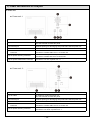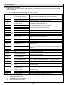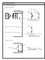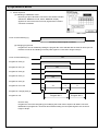
1
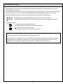
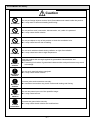
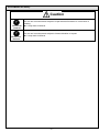
Aicure LED Line Type UV Curing Systems UD40 series (ANUD4S50) User’s manual WUME-ANUD4S50-01 2015.3|panasonic.net/id/pidsx/global Precaution on safety Precautions provided here are for prevention of hazards and damages to you and others by using the product safely and correctly. In order to indicate the level of hazards, damages and the degree of urgency, contents of precautions that are presumed to occur in the case of erroneous handling are classified into “warning” and “caution.” Both are important contents concerning safety, and hence must be observed without fail. Warning Contents with presumed possibility of death or severe injury for people Caution Contents with presumed risk of injury for people and occurrence of physical damage Pictogram example Symbols indicate prohibited actions. “Disassembly prohibited” in the picture to the left ● Symbols force or instruct actions. “Observe without fail” in the picture to the left Though we incorporate safety measures based on specification agreements, there is no guarantee from us whatsoever in the case of occurrence of safety issues. Likewise, there is no guarantee from us whatsoever for production halt and product defect caused by equipment failure, malfunction, problem, etc., human and physical damage due to failure of other companies’ merchandise equipped with the product, or related lawsuit and so forth. -2- Precaution on safety Warning Prohibited Prohibited Prohibited Prohibited Prohibited Use appropriate transport device and stay away from the underside of machinery. Use of inappropriate transport device may lead to dropping and causing injury. Do not install this equipment near important electronic apparatuses supporting human life. Users of pacemaker and so forth must stay away from the device during operation. Electromagnetic noises may cause errors in the function of life-support devices. Do not use in combustible gas atmosphere. It may result in explosion. Do not throw this product into the flame. It may cause explosion of electronic components. Do not see or catch on skin the direct or reflected light of LED while it’s on. It may cause disorders and inflammation in the eye or the skin. Be sure to observe Set up the unit in such manner to avoid exposure of human body to LED-UV light. Exposure to LED-UV light may cause disorders and inflammation in the skin. If there is a risk of exposure to LED-UV light and UV reflection, cover up with a shield with appropriate transmittance and thermal characteristics to block the UV light. Be sure to observe Be sure to wear protective glasses and protective gears when installing and operating. Failure to wear them may cause disorders and inflammation in the eye or the skin. Be sure to wear protective glasses that shield UV lights since the light emitted by this machine contains UV light of either 365nm/385nm. Be sure to observe Disassembly prohibited Be sure to perform cleaning of LED head while the power supply is cut off. Performing with the power supply on may cause disorders and inflammation in the eye or the skin as well as electric shocks. Do not disassemble or modify. It may cause accidents, injuries and electric shocks. It may result in abnormal heating and fuming. It may cause disorders and inflammation in the eye or the skin due to exposure to LED-UV light. -3- Precaution on safety Caution Prohibited Prohibited Prohibited Prohibited Be sure to observe Be sure to observe Be sure to observe Be sure to observe Ground connection Do not put foreign objects such as liquid, flammables and metals inside the product. It may result in abnormal heating and fuming. Do not perform work (connection, disconnection, etc.) while it is powered. It may cause electric shocks. Do not put objects on top of this product or block the ventilation hole. It may cause burnout due to heating. Do not touch with bare hands during radiation or right after radiation. It may cause burns due to high temperature. Use this product with a margin against its guaranteed characteristics and performance. Exceeding limit values of guaranteed characteristics and performance may result in breakage. Do not touch terminals when energized. It may cause electric shocks. Connect wires and connectors securely. Insufficient connection may result in abnormal heating and fuming. Do not use power input out of the specified range. It may cause burnout. Connect the ground wire securely. It may cause electric shocks and malfunctions. -4- Precaution on safety Caution Be sure to observe Be sure to observe Do not use in environments subject to major thermal fluctuation or occurrence of dewing. It may result in failures. Do not use in environments subject to intense vibration or impact. It may result in failures. -5- Usage Precautions Standard on the safety of LED products LED light source used in this product is the scope of application of “Photobiological Safety of Lamps and Lamp Systems (JIS C7550:2011, IEC62471:2006).” Standard : JIS C7550:2011, IEC62471:2006 Classification : Risk group 3 However, we recommend safety management equivalent to Class 4 under “Standard on the safety levels of laser products” in consideration of safety for users. <Reference: Standard on the safety levels of laser products> Standard : IEC60825-1 Edition2.0:2007 JIS C6802:2011 Classification : Class 4 LED products Wavelength : 365±10nm, 385±10nm <Safety control items> Do not see or catch on skin the direct or reflected light of LED while it’s on. (It may cause disorders and inflammation in the eye or the skin.) Set up the unit in such manner to avoid exposure of human body to LED-UV light. (Exposure to LED-UV light may cause disorders and inflammation in the skin. If there is a risk of exposure to LED-UV light and UV reflection, cover up with a shield with appropriate transmittance and thermal characteristics to block the UV light.) Be sure to wear protective glasses (UV light blocking) and protective gears when installing and operating. (Failure to wear them may cause disorders and inflammation in the eye or the skin.) *Handling of LED products overseas Though LEDs are currently excluded from the application of “Standard on the safety of laser products” under IEC and JIS as of current, older editions may be adopted in some countries and regions. Hence, please check the laser safety regulations and standards of the country of usage. -6- Usage Precautions Read product specifications and user’s manual thoroughly before usage and use it correctly. 1. Take external safety measures (interlocking, installation of smoke detector, etc.) so that a fail-safe mechanism will work for the entire system in the case of product failures or errors caused by external factors. 2. Do not disassemble or modify. It may result in failures. Warranty will be void for failure or breakage occurring from usage with disassembly and modification. 3. Power source voltage for this device is single phase, 200 to 240V AC (frequency of 50 to 60Hz). Do not use it on power source voltage and frequency deviating the provision in this manual. It may cause breakage. 4. Customers shall prepare the power cable (AC supply cable) with the diameter appropriate for the maximum input current (5A). 5. Securely connect the power cable to the terminal block (screw diameter ø4) on the back of the control unit. 6. Connect the ground wire securely. 7. Do not share the power line for this product with motors, machines with induction properties, or devices that consume large amounts of power. 8. Despite the sufficient resistance to noises superimposed on the power line, it is recommended to use an isolation transformer and so forth to attenuate noises before feeding the power. 9. Use the supplied cables for the connections among the control unit, power unit, and LED head. Make sure that the cables are connected securely. Warranty will be void for failure, breakage or destruction occurring from usage of products other than what’s designated or recommended by us. 10. When connecting cables to D-Sub37 connector for external I/O, perform soldering accurately to prevent short circuits between the terminals inside the connector. 11. When connecting an inductive load (motor or relay) to the external I/O, connect a noise absorber (noise killer and so forth) to the load side. 12. After finishing the connections of the power cable (AC supply cable), securely screw the terminal block cover to prevent electric shocks. 13. Hold the connector (plug) area when connecting/disconnecting the cables. 14. Wire the cables in such manner to avoid load and stress to the cables and connectors. 15. Place the rubber feet on a horizontal surface. Do not install in tilted, sidelong, or flipped positions. It may cause breakage due to occurrence of heating. 16. Do not install in a sealed space. 17. Do not block the ventilation hole of the power unit. 18. Please have a margin to installation space, and do not allow the exhaust air from the fan to enter through the air intake. 19. Check that all the connections are correct before turning on the power. 20. Installation environment: Ambient temperature 0 to +35 C Ambient humidity 30 to 85%RH (at 25C, no dewing or freezing) A place free from dust, oil smoke, conductive dust, corrosive or flammable gas, salt content, and iron dust A place free from splashes of water, oil and chemicals A place free from sudden temperature changes, vibration and shocks A place free from direct sunlight A place free from high magnetic field and intense electric field -7- Usage Precautions Warranty Products and specifications described in this document are subject to change without notice for product improvement and so forth (including specification changes and discontinued production). Upon considering using these products or placing orders, please check whether the information provided in this document is up to date by contacting our inquiry desk as necessary. Though we make utmost efforts on quality control of this product, 1. we would like to ask you to consult our inquiry desk and exchange specification documentation in the case that the application may entail usage beyond the range of specifications, environments and conditions provided in this document or in the case of applications requiring especially high reliability such as usage under conditions and environments not prescribed or safety devices and control systems such as railways, aviation and medical use. 2. In order to prevent the occurrence of unexpected troubles regarding matters not provided in this document, please consult about the specifications of your product, its customers, usage condition for this product, details on the area this product is mounted, etc. 3. Take external safety measures such as a redundant circuit so that a fail-safe mechanism will work for the entire system in the case of product failures or errors caused by external factors. Please use this product with a margin against the values of its guaranteed characteristics and performance as provided in this document. 4. Please perform acceptance inspection with purchased or delivered articles in a timely manner and also carry out the handling of this product before and during the acceptance inspection with sufficient consideration on controlled maintenance. Warranty period In the case of failures for which we are to be held responsible within 1 year from technical acceptance, we will perform the repair or provide the parts free of charge. However, warranty period shall be 1 year from accounting acceptance in the case that technical acceptance is not performed within 15 days from accounting acceptance due to reasons on your side or that the article about deeming accounting acceptance as technical acceptance out of articles concerning accounting acceptance prescribed on product specification sheet is to be applied. Warranty coverage In the case of failure or flaw with this product revealed during the warranty period for which we are to be held responsible, we will provide substitute articles or required replacement parts or replace or repair the flawed part free of charge. However, failures and flaws corresponding to the following will be excluded from the scope of this warranty. 1. If it is due to the specifications, standards, handling methods, etc. ordered by you. 2. If it is caused by modifications on the structure, performance, specifications, etc. performed after purchase or after delivery without any involvement from us. 3. If it is due to a phenomenon that cannot possibly be foreseen by the technology made available at the time of the purchase or contract. 4. If the usage deviated from the range of conditions and environments prescribed in the catalog, specification sheet, and user’s manual. 5. In the case of damages that could be avoided if your devices, into which this product is integrated for use, retain functions and structures that should naturally be equipped by common sense in the industry. 6. If it is due to natural disasters, infliction by a third party, or an act of God. 7. If the failure is due to specifications deviating from power source specification recommended by us or the power source. 8. Other cases where our responsibility is not clarified through failure analysis. 9. If the device is damaged due to corrosion caused by poisonous gases in the vicinity. 10. In the case of occurrence due to use of products not designated or recommended by us. 11. In the case of occurrence due to usage with disassembly and modification. 12. If it is caused by relocation from the original position at the time of technical acceptance. 13. If it is due to scratches, damages, erroneous connection, or erroneous setup upon assembling the apparatus. 14. If it is used without performing appropriate maintenance. 15. In the case of minor performance change that can be compensated by output adjustment and so forth. 16. Concerning consumables and secondary materials such as filter. 17. Other cases where free warranty is not granted based on our judgment. The warranty as mentioned herein is limited to the warranty on the sole unit of this purchased or delivered product, and damages brought about due to failures or flaws of this product will be excluded. This warranty is applied to the application at the time of purchase. Please contact us when changing the application or relocating abroad. Location to which free services are applicable Final delivery address in Japan designated at the time of order or location of your staff in charge of this device in Japan. -8- Usage Precautions Warranty Handling of overseas relocation If this device is taken outside of Japan by the hands of you or final users, the scope of 12-month free services will only include provision of replacement parts to the designated domestic location and free repair on the device sent to us, and on-location support by us or local agents will be provided for a fee. Production warranty Losses due to production halt caused by failures of this device and losses incurred due to defects will not be compensated. Safety warranty Make sure to perform any maneuver such as maintenance or trouble shooting where human body parts such as hands and fingers touch the equipment after shutting down the power source. It may lead to electric shocks or other disasters. Though safety covers and switches will be installed in line with directions from you based on specification agreements, safety issues occurring during usage will not be guaranteed by us. Responsibility for flaws Flaws of the device resulting from the specifications, standards, handling methods, etc. ordered by you will not be guaranteed. Responsibility due to usage methods deviating from specifications If due to usage method deviating from specifications, there will be no warranty on safety, environment, device, etc. nor any warranty on the resulting problems. Also, device troubles caused by this will be excluded from the warranty regardless of the warranty period. Warranty on LED head Warranty on the LED head will, in contrast to the warranty for this product (UD40 controller), be in accordance with the content of the specification sheet and manual for the LED head. -9- Table of Contents Safety Precautions ・・・・・・・・・・・・・・・・・・・・・・・・・・・・・・・・・・・・・・・・・・・・・・・・・・・・・・・・・・・・・・・・・・・・ 2 Usage Precautions ・・・・・・・・・・・・・・・・・・・・・・・・・・・・・・・・・・・・・・・・・・・・・・・・・・・・・・・・・・・・・・・・・・・・・ 6 1) Device overview 1. Function overview description ・・・・・・・・・・・・・・・・・・・・・・・・・・・・・・・・・・・・・・・・・・・・・・・・・・・・・・・・・・ 11 2. Features ・・・・・・・・・・・・・・・・・・・・・・・・・・・・・・・・・・・・・・・・・・・・・・・・・・・・・・・・・・・・・・・・・・・・・・・・・・・・ 11 3. Device configuration ・・・・・・・・・・・・・・・・・・・・・・・・・・・・・・・・・・・・・・・・・・・・・・・・・・・・・・・・・・・・・・・・・・ 11 4. Basic specifications ・・・・・・・・・・・・・・・・・・・・・・・・・・・・・・・・・・・・・・・・・・・・・・・・・・・・・・・・・・・・・・・・・・・ 12 5. Outline drawing ・・・・・・・・・・・・・・・・・・・・・・・・・・・・・・・・・・・・・・・・・・・・・・・・・・・・・・・・・・・・・・・・・・・・・・ 14 2) Installation of device 1. Installation environment ・・・・・・・・・・・・・・・・・・・・・・・・・・・・・・・・・・・・・・・・・・・・・・・・・・・・・・・・・・・・・・・ 17 2. Work at your expense ・・・・・・・・・・・・・・・・・・・・・・・・・・・・・・・・・・・・・・・・・・・・・・・・・・・・・・・・・・・・・・ 17 3. Installation of device ・・・・・・・・・・・・・・・・・・・・・・・・・・・・・・・・・・・・・・・・・・・・・・・・・・・・・・・・・・・・・・・・・・ 17 4. Space for installation ・・・・・・・・・・・・・・・・・・・・・・・・・・・・・・・・・・・・・・・・・・・・・・・・・・・・・・・・・・・・・・・・ 18 5. Wiring method ・・・・・・・・・・・・・・・・・・・・・・・・・・・・・・・・・・・・・・・・・・・・・・・・・・・・・・・・・・・・・・・・・・・・・・・ 19 6. Primary power source connection ・・・・・・・・・・・・・・・・・・・・・・・・・・・・・・・・・・・・・・・・・・・・・・・・・・・・・・ 20 7. Wiring ・・・・・・・・・・・・・・・・・・・・・・・・・・・・・・・・・・・・・・・・・・・・・・・・・・・・・・・・・・・・・・・・・・・・・・・・・・・・・・ 20 3) Names and functions of each part 1. Control unit ・・・・・・・・・・・・・・・・・・・・・・・・・・・・・・・・・・・・・・・・・・・・・・・・・・・・・・・・・・・・・・・・・・・・・・ 21 2. Power unit ・・・・・・・・・・・・・・・・・・・・・・・・・・・・・・・・・・・・・・・・・・・・・・・・・・・・・・・・・・・・・・・・・・・・・・22 3. LED head ・・・・・・・・・・・・・・・・・・・・・・・・・・・・・・・・・・・・・・・・・・・・・・・・・・・・・・・・・・・・・・・・・・・・・・・23 4) Touch screen 1. Touch screen display ・・・・・・・・・・・・・・・・・・・・・・・・・・・・・・・・・・・・・・・・・・・・・・・・・・・・・・・・・・・・24 2. Description on touch screens and switching between screens ・・・・・・・・・・・・・・・・・・・・・・・・・・・・・・ 24 5) Operation of device 1. LOCAL / REMOTE common items ・・・・・・・・・・・・・・・・・・・・・・・・・・・・・・・・・・・・・・・・・・・・・・・・・・・・・・ 25 2. Data menu ・・・・・・・・・・・・・・・・・・・・・・・・・・・・・・・・・・・・・・・・・・・・・・・・・・・・・・・・・・・・・・・・・・・・・・・・・・ 27 3. Program setup ・・・・・・・・・・・・・・・・・・・・・・・・・・・・・・・・・・・・・・・・・・・・・・・・・・・・・・・・・・・・・・・・・・・・・・・ 28 4. Manual operation ・・・・・・・・・・・・・・・・・・・・・・・・・・・・・・・・・・・・・・・・・・・・・・・・・・・・・・・・・・・・・・・・・・・・・ 29 5. Operation by external signal ・・・・・・・・・・・・・・・・・・・・・・・・・・・・・・・・・・・・・・・・・・・・・・・・・・・・・・・・・・・ 30 6) Error display 1. Error display ・・・・・・・・・・・・・・・・・・・・・・・・・・・・・・・・・・・・・・・・・・・・・・・・・・・・・・・・・・・・・・・・・・・・・・・・・ 35 2. Error items and contents ・・・・・・・・・・・・・・・・・・・・・・・・・・・・・・・・・・・・・・・・・・・・・・・・・・・・・・・・・・・・・・ 35 3. Emergency stop ・・・・・・・・・・・・・・・・・・・・・・・・・・・・・・・・・・・・・・・・・・・・・・・・・・・・・・・・・・・・・・・・・・・・・・ 37 7) Maintenance list ・・・・・・・・・・・・・・・・・・・・・・・・・・・・・・・・・・・・・・・・・・・・・・・・・・・・・・・・・・・・・・・・・・・・・・・ 38 8) Troubleshooting ・・・・・・・・・・・・・・・・・・・・・・・・・・・・・・・・・・・・・・・・・・・・・・・・・・・・・・・・・・・・・・・・・・・・・・・・ 39 9) Manual revision history ・・・・・・・・・・・・・・・・・・・・・・・・・・・・・・・・・・・・・・・・・・・・・・・・・・・・・・・・・・・・・・・・・ 40 - 10 - 1) Device overview 1. Function overview description This device is an ultraviolet hardening device that swiftly hardens UV resins (ink, adhesive & paint) by radiating ultraviolet from its LED light source. UV radiation onto objects in various radiation widths is made possible by freely changing the radiation area. 2. Features 1. Major reduction in power consumption: Power consumption can be kept low in comparison to conventional lamp type. 2. With forced cooling with a fan, it requires no such equipment as chillers for LED cooling. 3. Extensive size variation is available. 4. Flexible UV radiation is possible. 5. Exhaust duct is not required, contributing to maintaining a clean environment. 6. Low-temperature radiation containing no infrared reduces thermal impact on the object. 7. Downsized power unit and absence of exhaust blower save space. 8. Lifetime is longer than conventional lamp-type UV lamp reducing the burden of maintenance. 3. Device configuration This devices consists of the control unit, power unit, and LED head (radiation unit). Control unit PLC-based controller Power unit Power source to light LED LED head Forced air-cooled type LED head with fan Note) Prepare LED head separately. - 11 - 1) Device overview 4. Basic specifications Controller part number Power unit type ANUD4S50 Power unit - 1 ANUD4P32N Power unit - 2 ANUD4P21X Number of LED head blocks to be handled Rated Part number of corresponding LED head λ: 365nm ANUD4A511 λ: 385nm ANUD4B511 Input power supply voltage Single phase AC 200 to 240V Input power supply frequency 50 to 60Hz Maximum input current 5A Maximum power consumption 550W Number of radiation program patterns 32 patterns*1 Display / setting / operation Display / setting / operation from touch screen External control Type Parallel I/O (D-Sub37*2) External input LED lighting / program selection / individual LED block lighting Local-remote switching / external emergency stop External output Dimming control*1 Performance Peak radiation intensity*3 Main unit emergency stop Function to detect LED heard temperature to stabilize UV output Radiation distance: 10mm 4,200mW/cm2 (at 365nm) / 4,600mW/cm2 (at 385nm) Radiation distance: 30mm 2,300mW/cm2 (at 365nm) / 2,600mW/cm2 (at 385nm) Radiation distance: 10mm 36mm (with 1-block radiation), 108mm (with consecutive 2-block radiation) 180mm (with consecutive 3-block radiation) 252mm (with consecutive 4-block radiation) 324mm (with full-block radiation) Radiation distance: 30mm 16mm (with 1-block radiation), 88mm (with consecutive 2-block radiation) 160mm (with consecutive 3-block radiation) 232mm (with consecutive 4-block radiation) 304mm (with full-block radiation) Effective radiation width*3 Circumstantials Equipment power ON / LED radiation ready / during radiation / warning / Error 50% to 100% (in increments of 1%) LED temperature feedback *1 *2 *3 5 blocks Speculated LED head life*3 15,000 hours (at the point of 70% against initial UV intensity) Operating ambient temperature 0 to +35ºC Operating ambient humidity 30 to 85%RH (at 25°C, no dewing or freezing) Storage ambient temperature -10 to +60ºC Storage ambient humidity 30 to 85%RH (at 25°C, no dewing or freezing) To be set from touch screen. Customers shall prepare the cable to be connected to D-Sub37 connector. By our measurement standards. Representative value, not guaranteed value. Check the specification sheet and manual of LED head for basic specifications of the LED head itself. - 12 - 1) Device overview Configuration Control unit equipped with PLC, power supply for LED lighting Separate type radiation unit equipped with UV-LED AC inlet Terminal block (screw diameter of terminal block: ø4) *4 Control unit Cooling method Power unit LED head Structure Control unit Outer surface finish Size*5 Miscellaneous Weight*6 *4 *5 *6 *7 Power unit Fan-less natural air-cooling Forced air-cooling with fan Matte black coat LED head A5052 cover (black anodized finish) Control unit W×H×D=280mm×222.2mm×560mm Power unit W×H×D=280mm×301mm×326mm LED head W×H×D=50mm×477mm×142mm Control unit Approx. 15kg Power unit - 1 Approx. 14kg Power unit - 2 Approx. 12kg LED head Approx. 3.5kg Outline drawing See P.14 to 16 Space for installation See P.18 Wiring type See P.19 Included items Control unit Power keys, D-Sub37 connector Power unit Signal cable, AC connection cable, LED head connection cable LED head Connector for power source wiring (NJW-2824-PF16, NJW-2824-PFX16)*7 Customers shall prepare the power cable (AC supply cable) with the diameter appropriate for the maximum input current (5A). Excluding protruding parts of connectors and cables Excluding connectors and cables If the LED head is purchased together with the controller, the LED connection cable accompanying the controller will be used, and the power wire connector included in LED head will not be used. - 13 - 1) Device overview 5. Outline drawing (unit: mm, protrusions not included) Control unit - 14 - 1) Device overview Power unit - 15 - 1) Device overview LED head Number of blocks Outline dimension drawing shown above is an example of the 3-block version. Please refer to the table for dimensions A-C. Products with 4-6 blocks will have 2 connectors to be connected to the main unit. - 16 - 2) Installation of device 1. Installation environment 1.Ambient temperature: 0 to +35°C, ambient humidity: 30 to 85%RH (at 25°C), no dewing or freezing 2.Must be a place free from dust, oil smoke, conductive dust, corrosive or flammable gas, salt content, and iron dust. 3.Must be a place free from splashes of water, oil and chemicals. 4.Must be a place free from sudden temperature changes, vibration and shocks. 5.Must be a place free from direct sunlight. 6.Must be a place free from high magnetic field and intense electric field. 2. Work at your expense 1.Installation and wiring work with device at installation location 2.Power source to feed to device and related wiring work • Primary power supply work 3.Works other than what is prescribed as work to be done at our expense on estimate sheet 3. Installation of device [Control unit, power unit] 1.Place the rubber feet on a horizontal surface. 2.Do not install in tilted, sidelong, or flipped positions. It may cause breakage due to occurrence of heating. 3.Do not install in a sealed space. 4.Do not block the ventilation hole of the power unit. 5.Please have a margin to installation space, and do not allow the exhaust air from the fan to enter through the air intake. 6.Take external safety measures (interlocking, installation of smoke detector, etc.) so that a fail-safe mechanism will work for the entire system in the case of product failures or errors caused by external factors. [LED head] 1.Do not block the ventilation hole. It may result in abnormal heating. 2.Do not touch the radiation window (glass) with bare hands. It may cause taint. 3.UV radiation unit (radiation window) is protected by glass. Impact to this area may cause breakage of glass. Stains in this area may reduce UV output intensity. Wipe taint, if any, with alcohol (ethanol, IPA) thoroughly. 4.See the LED head specification sheet, user’s manual, etc. for details needed for appropriate installation. - 17 - 2) Installation of device 4. Space for installation ●LED head 50 or more 150 or more 50 or more Do not install the control unit, power unit, and LED head in a sealed space. Please have a margin to installation space, and do not allow the exhaust air from the fan to enter through the air intake. Perform installation of LED head to customer’s equipment securely using total of 8 pieces of M4 screws on the side faces of the head. (Standard tightening torque: 1.0N·m) See the LED head specification sheet and installation work description documents for details on LED head installation needed for appropriate installation. - 18 - 2) Installation of device 5. Wiring method • • • Use the supplied cables for the connections among the control unit, power unit, and LED head. Make sure that the cables are connected securely. Customers shall prepare the power cable (AC supply cable) with the diameter suited to withstand the maximum input current (5A). Use AWG #20 to 28 wires for the cable to D-Sub37 connector for external I/O and perform soldering accurately to prevent short circuits between the terminals inside the connector. - 19 - 2) Installation of device 6. Primary power source connection 1.Supply single phase 200V to 240V (frequency of 50Hz to 60Hz) for power source voltage. 2.Customers shall prepare the power cable (AC supply cable) with the diameter appropriate for the maximum input current (5A). 3.Securely connect the power cable to the terminal block (screw diameter ø4) on the back of the control unit. Make sure the primary power is cut off when connecting. It may cause electric shocks. Be sure to observe 4.Be sure to connect the power ground wire. Usage without ground connection may lead to electric shocks and device troubles. Ground connection 5.After finishing the connections of the primary power source, securely screw the terminal block cover to prevent electric shocks. 6.Do not share the power line for this product with motors, machines with induction properties, or devices that consume large amounts of power. 7.Despite the sufficient resistance to noises superimposed on the power line, it is recommended to use an isolation transformer and so forth to attenuate noises before feeding the power. 7. Wiring 1.Use the supplied cables for the connections among the control unit, power unit, and LED head. See P.19 for reference, and make sure that the cables are connected securely. 1.Use AWG #20 to 28 wires for the cable to D-Sub37 connector for external I/O and perform soldering accurately to prevent short circuits between the terminals inside the connector. 2.When connecting an inductive load (motor or relay) to the external I/O, connect a noise absorber (noise killer and so forth) to the load side. 3.Hold the connector (plug) area when connecting/disconnecting the cables. 4.Wire the cables in such manner to avoid load and stress to the cables and connectors. 5.Due to the external emergency stop function, this device cannot be used without #17 and #18 pins of external I/O connector being shorted. 6.Use dry contacts for the wiring to short #17 and #18 pins of external I/O connector. - 20 - 3) Names and functions of each part 1. Control unit Name Function (1) Circuit breaker AC power is supplied to the equipment. (2) Pilot lamp When AC is supplied and the breaker is on, the light stays on. (3) Key switch The equipment can be started or stopped. (4) Touch screen Each setting and display are available. (5) Emergency stop switch This starts an emergency stop and stops UV radiation. To recover from an emergency stop, follow instructions provided on the touch screen. (6) Radiation switch / Radiation underway lamp This switch starts or stops UV radiation in manual mode. During UV irradiation, red light stays on. (7) AC supply connector Connector for AC power supply to power unit - 1 Connects to “AC IN” of power unit - 1. (8) Power unit communication connector - 1 Connector for communication with power unit - 1 Connects to “CNT IN” of power unit - 1. (9) External I/O connector For connection with external apparatuses such as PLC (See P.30 for connector pin numbers and signal content.) (10) Grounding terminal Terminal for ground wire connection (screw diameter of terminal block: ø4) (11) AC power receiving terminal Terminal for AC 200 to 240V connection (screw diameter of terminal block: ø4) (12) Power unit communication connector - 2 Connector for communication with power unit - 2 Connects to “CNT IN” of power unit - 2. - 21 - 3) Names and functions of each part 2. Power unit Power unit - 1 Name Function (1) Air intake Air intake for cooling the power unit. The anti-dust filter is inside the panel. (2) Exhaust port Exhaust opening for discharging heat produced inside the power unit. (3) LED head connection connector For connection with LED head (4) Power unit communication connector Connector for communication with control unit Connects to “HEAD1 CNT OUT 1” of control unit. (5) AC power receiving connector Connector for reception of AC power Connects to “HEAD1 AC OUT” of control unit. (6) AC power transmission connector The connector allows AC power to be supplied to the second power unit. Connects to “AC IN” of power unit - 2. Power unit - 2 Name Function (1) Air intake Air intake for cooling the power unit. The anti-dust filter is inside the panel. (2) Exhaust port Exhaust opening for discharging heat produced inside the power unit. (3) LED head connection connector For connection with LED head (4) Power unit communication connector Connector for communication with control unit Connects to “HEAD1 CNT OUT 2” of control unit. (5) AC power receiving connector Connector for reception of AC power Connects to “AC OUT” of power unit - 1. - 22 - 3) Names and functions of each part 3. LED head Exhaust fan LED head connection cable 4 M4 depth 6 (Opposite side is identical.) Mounting screws (Opposite side is identical.) Aiv intake area (Opposite side is identical.) Details of mounting portion F.G. connection screw M4 screw depth 5.5 UV emitting window Outline drawing of 3B version is shown as an example of LED head. See the LED head specification sheet and installation work description documents for details. - 23 - 4) Touch screen 1. Touch screen display The following screens are displayed on the touch panel. Initial screen Main screen Data menu screen Data confirmation screen Operating time confirmation screen Error screen Main unit Emergency stop screen Language selection screen Program setup screen External Emergency stop screen Error confirmation screens 2. Description on touch screens and switching between screens 1.Initial screen Turn ON control unit circuit breaker to display the initial screen as shown to the right after touch screen initialization is complete. In the language of the inverted state by pressing the switch of the language selection, , the touch panel is displayed. PLC software version is shown in the bottom right corner of screen. 2.Startup preparation screen Turn ON the key switch to jump to startup preparation screen and start initialization of the device. Switches to main screen upon completion of startup preparations. Initial screen 3.Main screen Various switches are displayed. Major ones include the following: • Temperature Feedback ON / OFF Switch for activation of detection of LED head temperature to stabilize UV intensity • Data menu Switches to data menu screen. • LED wavelength 365nm / 385nm Displays LED wavelength of connected LED head. Startup preparation screen • LOCAL / REMOTE Displays control type of UD40 controller. LOCAL : Manual operation is possible from control unit. REMOTE: Controlled by signal input to external I/O connector. • Program No. Displays selected program No. When LOCAL : Modification is possible by touching the number field. REMOTE : Displays program No. set by external signal. • LED head Displays lit LED blocks as illustrated in the bottom left corner of screen. - 24 - Main screen 5) Operation of device 1. LOCAL / REMOTE common items Front panel Main screen (1)“EMERGENCY” switch Press this switch to turn the device into emergency stop, jump to main unit emergency stop screen, and stop UV radiation. Follow the procedure displayed on touch screen to resume from emergency stop state. (2)“Temperature feedback ON / OFF” key By pressing this key and achieving “temperature feedback ON,” the function to detect LED head temperature and stabilize UV intensity will be activated. Main unit emergency stop screen However, this function will be deactivated even under “temperature feedback ON” if the dimming rate is set to 100% in program setting screen as in P.28. Also, this function will be deactivated if the dimming rates are not identical for all the blocks of LED head. Temperature feedback ON state Temperature feedback invalid state (3)“LED head” status display area Displays lit LED blocks while LED radiation is on, as illustrated in the bottom left corner of screen. (4)“Data menu” key Press this key to jump to data menu screen. See P27 for details. UV radiation underway screen - 25 - 5) Operation of device (5)Warning display “Warning“ message appears on screen when LED lighting time and fan working time come close to the preset lifetime. Press this area when this message is displayed to jump to “operating time confirmation” screen, where details of the warning can be checked. Data menu screen Block No. of LED and fan approaching preset lifetime will be displayed inversed and blinking. Please contact our inquiry desk as the LED and fan will soon need to be replaced. Operating time confirmation screen - 26 - 5) Operation of device 2. Data menu Press “data menu” key on main screen to jump to data menu screen. Description on each key Press the keys on touch screen to switch screens and carry out the following confirmation, settings, and actions. Data menu screen (1) Data confirmation screen This screen displays the dimming rate of the selected program No. as well as LED temperature of each block of the current LED head. It is also possible to switch temperature feedback ON/OFF on this screen. Data confirmation screen (2) Operating time confirmation screen This screen allows confirmation of lighting time of LED on each block of the LED head as well as working time of the fan. Operating time confirmation screen (4) Language selection screen In this screen, can switch the display language on the touch panel. Language selection screen (4) Program setup screen Dimming rate of LED when lit can be set in this screen. Details will be explained in the next section. (5) “ESC” key Press this key to go to the previous screen. - 27 - 5) Operation of device 3. Program setup Press “program setup” key on data menu screen to jump to program setup screen. LED head lighting conditions can be set in this screen. Description on each key The following confirmation and settings will be enabled by pressing the keys on touch screen. Program setup screen (1) “” and ”” keys Press these keys to modify program No. Program No. takes the range of 0 to 31, and turns to “31” when “” is pressed in the state of “0” and turns to “0” when “” is pressed in the state of “31.” Also, the set dimming rate for each LED block corresponding to the program No. will be displayed on screen, and if the set dimming rate appears as “0%,” that LED block is set to not illuminate the LED. (2) Dimming rate input screen Keyboard pops up on screen by touching the number field of the set dimming rate on screen, allowing entry of dimming rate. Keyboard allows entry of dimming rate of 0% and 50 to 100%, which will be determined by pressing “ENT” after entering the number. If a number exceeding 100% is entered and “ENT” is pressed, it is deemed as input error and user will be prompted to re-enter the number. If a number from 1 to 49% is entered and “ENT” is pressed, it will automatically be converted to 50%. The block will not be illuminated when turning on LED if the dimming rate is set at 0%. Dimming rate input screen Press ”CLR” to clear the entered value. Press “BS” to delete 1 last character of the number entered last. Press “ESC” to cancel the input. Press “ENT” key and set the dimming rate on keyboard to display 2 keys to the right of the screen. (3) “Confirm” key Press this key to finalize the entered dimming rate. (4) “Cancel” key Press this key to discard the entered dimming rate and restore the state before modification. (5) “END” key Press this key to finish dimming rate setting, save the set dimming rate in memory, and return to the previous screen. Please note that the set dimming rate data will not be saved in memory if the device is powered off before pressing this “finish” key. - 28 - Dimming rate confirmation, cancel screen 5) Operation of device 4. Manual operation Allows for manual operation of UD40 controller when in “LOCAL” state on main screen. Front panel Main screen Description on each key The following actions will be taken when switches and keys on touch screen in the front panel of control unit are pressed. (1) “EMISSION” switch Press this switch to light LED head under radiation conditions for the selected program No. The lamp of this switch is lit while LED is on. Press the switch again while LED is on to turn off LED and the lamp goes off as well. Displays lit LED blocks while LED radiation is on, as illustrated in the bottom left corner of screen. UV radiation underway screen (2) “Program No.” key Touch the number field of “program No.” to display keyboard on screen and enable entry of program No. Keyboard allows entry of program No. from 0 to 31, and the program No. will be finalized by pressing “ENT” after entering the number. If a number other than 0 to 31 is entered and “ENT” is pressed, it is deemed as input error, user will be prompted to re-enter the number, and program No. will not be finalized. Press ”CLR” to clear the entered value. Press “BS” to delete 1 last character of the number entered last. Press “ESC” to cancel the input. - 29 - Program No. input 5) Operation of device 5. Operation by external signal UD40 controller can be controlled by external devices by sending signals into “External I/O” connector on the back side of control unit. 1. Pin-out and descriptions for External I/O connector (D-Sub37) Pin No. I/O Signal name Content Local / remote switching Enable external signal control (remote control) when ON *1 2 LED lighting Light LED head under selected program conditions when ON*1 3 Program No. change pulse Modify program No. by one-shot ON*2 signal. 4 Program No. bit - 0 5 Program No. bit - 1 6 Program No. bit - 2 7 Program No. bit - 3 8 Program No. bit - 4 9 LED - 1 ON Light block 1 of LED head when ON*1 LED - 2 ON Light block 2 of LED head when ON*1 LED - 3 ON Light block 3 of LED head when ON*1 12 LED - 4 ON Light block 4 of LED head when ON*1 13 LED - 5 ON Light block 5 of LED head when ON*1 14 NC Not connected. (not used.) 15 Reserve input - 1 Reserve input 16 Reserve input - 2 Reserve input 17 External emergency stop - 1 18 External emergency stop - 2 Device goes to emergency stop when OPEN. (Dry contacts independent from other signals must be used for his signal.) 19 Common input Common for Nos. 1 to 16 signals (for input) NC Not connected. (not used.) 29 Equipment power ON ON*3 when power is fed to device (ON*3 to be maintained upon occurrence of errors as well) 30 LED radiation ready ON*3 when LED radiation is possible (OFF*4 during radiation on all blocks, at the time of errors) 31 LED radiation underway ON*3 at the time of LED radiation (OFF*4 only when lights are off on all blocks) Warning ON*3 when LED or fan reaches end of life warning status Occurrence of equipment error OFF*4 at the time of device errors (content of error to be checked on touch screen) 34 Equipment main unit under emergency stop OFF*4 upon emergency stop on device’s main unit 35 Reserve output - 1 Reserve output 36 Reserve output - 2 Reserve output 37 Common output Common for Nos. 29 to 36 signals (for output) 10 11 INPUT 1 32 33 *1 *2 *3 *4 OUTPUT 20-28 Designate LED lighting program No. Set program No. with total of 5 bits (32 ways). Set program contents from touch screen. Shorted with common input One-shot pulse with 0.3sec or longer shorting with common input Shorted state with common output Open state with common output - 30 - 5) Operation of device 2. Input and output specifications Input specifications Connection example UD40 controller side Open collector Relay contact Internal circuit INPUT 24V COM [Caution] Rated input voltage: 24V Maximum input current: 10mA Relay contact External emergency stop - 1 (No.17 pin) External emergency stop - 2 (No.18 pin) [Caution] Dry contacts must be used for external emergency stop. Maximum rated voltage: 30V DC Maximum rated amperage: 1A DC Output specifications UD40 controller side OUTPUT [Caution] Output type : Relay contact output Maximum rated voltage : 30V DC Maximum rated amperage : 1A DC Internal circuit COM - 31 - 5) Operation of device 3. Action sequence (1) Switching to “REMOTE” mode By turning #1 pin of D-Sub37 connector to ON, UD40 controller switches to “REMOTE” mode, where “REMOTE” display appears on main screen and control by signals from D-Sub37 connector is enabled. Main screen Local / remote switching (1) ON Control by external signal is enabled. (2) Changing program No. Program No. can be modified by setting the program No. to be selected with the 5 bits of #4 to 8 pins of D-Sub37 connector and feeding one-shot pulse signal of 0.3 second or longer to #3 pin. Local / remote switching (1) ON Program No. bit-0 (4) ON Program No. bit-1 (5) ON Program No. bit-2 (6) ON Program No. bit-3 (7) ON Program No. bit-4 (8) ON Program No. to be set 1 Program No. change pulse (3) ON Program No. set 31 3 0 ON Program No.1 Program No.3 Items to note) Program No. will no be changed by just modifying the 5 bits of #4 to 8 pins of D-Sub37 connector. Modification of program No. cannot be done without feeding one-shot pulse signal of 0.3 second or longer to #3 pin. - 32 - 5) Operation of device (3) Lighting LED head LED head will be lit under the selected program conditions while #2 pin of D-Sub37 connector is ON. Local / remote switching (1) ON LED lighting (2) ON UV radiation (4) Individual lighting of each LED block LED block of corresponding LED head will be lit under the selected program conditions while #9 to 13 pins of D-Sub37 connector are ON. Local / remote switching (1) ON LED 1~5 ON (9~13) ON Corresponding block radiates UV. Items to note) If the dimming rate is set to 0% (no to be lit) condition in the corresponding program condition, this signal will be ignored and LED will not be lit. - 33 - 5) Operation of device (5) Output signal Output signals (excluding reserve output) on #29 to 34 pins of D-Sub37 connector are generated in a sequence as follows. ON Equipment circuit breaker Key switch ON Equipment power ON (29) ON LED radiation ready (30) LED radiation underway (31) Occurrence of equipment error (33) ON ON ON ON ON ON ON ON (note: normal state) Occurrence of error Equipment main unit under emergency stop (34) ON (note: normal state) ON Main unit emergency stop LED lighting (2) ON Items to note) • “Equipment power ON” on #29 pin turns ON when device’s circuit breaker is ON and PLC inside the device is ready, and the ON state will be maintained until device circuit breaker is turned OFF. Use as a signal to check from external devices whether the power to UD40 controller is ON. • “LED radiation ready” signal on #30 pin goes OFF only at the time of error occurrence during full-block radiation, and the ON state will be maintained as long as there is any LED block that can be turned ON when LEDs of individual blocks are lit. • “Occurrence of equipment error” signal on #33 pin and “Equipment main unit under emergency stop” on #34 pin have ON signal when there is no error. • “Occurrence of equipment error” on #33 pin goes OFF when there is an error with the system, when the emergency stop button of the main unit is pressed, and when the external emergency stop signal is lost. • “Warning” signal on #32 pin turns ON only in the case of occurrence of warning state, and will not be affected by other signals. - 34 - 6) Error display 1. Error display Upon occurrence of errors in the device, the following screen is displayed, where error items appear in black and the buzzer beeps. Device comes to complete halt state upon occurrence of errors. Press “Buzzer” key to stop the buzzer. Press “RESET” after inspecting the area of error occurrence and solving the abnormality to return to main screen by way of startup preparation screen. When pressed the language part, can change the display language. Press the error item key displayed in black color to jump to detailed error content display screen. 2. Error items and contents (1) LED head connection error This is an error that occurs when the connection of LED head cannot be confirmed. Possible causes • Are the connections correct between control unit, power unit, and LED head? • Is there any snapped wire in the cables? • Please contact our inquiry desk if this error occurs in spite of proper connection. LED head connection error screen (2) LED lifetime reached This is an error that occurs when the accumulated lighting time of LED reaches the preset lifetime. Applicable LED blocks have the values in No. field inversed and blinking. Please contact our inquiry desk as the LED needs to be replaced. LED lifetime reached screen - 35 - 6) Error display (3) LED temperature error This is an error that occurs when LED temperature takes an abnormal value. Applicable LED blocks have the values in No. field inversed and blinking. Possible causes • Is the LED head fan working? • Aren’t the air inlet and outlet of LED head blocked? • Isn’t there any accumulation of dust around LED head? LED temperature error screen • Isn’t there any snapped wire in LED head connection cable? (4) Power supply error There is an error in the power supply for lighting LED. Applicable LED blocks have the values in No. field inversed and blinking. Possible causes • Isn’t there any damage to LED such as snapped wire or short circuit? • Isn’t there any snapped wire in the cables? • Please contact our inquiry desk if this error occurs at all times, which may indicate a power supply failure. Power supply error screen (5) Fan lifetime reached This is an error that occurs when the accumulated working time of LED head fan reaches the preset lifetime. Applicable LED blocks have the values in No. field inversed and blinking. Please contact our inquiry desk as the fan needs to be replaced. Fan lifetime reached screen (6) Fan revolution dropping This is an error that occurs when the revolution of LED head fan drops. Applicable LED blocks have the values in No. field inversed and blinking. Possible causes • Is the LED head fan working? • Aren’t the air inlet and outlet of LED head blocked? • Isn’t there any accumulation of dust around LED head? • Isn’t there any snapped wire in LED head connection cable? - 36 - Fan revolution dropping screen 6) Error display (7) Current out of range error This is an error that occurs when LED current is out of range. Applicable LED blocks have the values in No. field inversed and blinking. Possible causes • Isn’t there any damage to LED such as snapped wire or short circuit? • Isn’t there anomaly of power supply? • Isn’t there any snapped wire in LED head connection cable? Current out of range error screen (8) Sudden change in voltage error This is an error that occurs when LED voltage has changed rapidly. Applicable LED blocks have the values in No. field inversed and blinking. Possible causes • Isn’t there any damage to LED such as snapped wire or short circuit? • Isn’t there anomaly of power supply? • Isn’t there any snapped wire in LED head connection cable? Sudden change in voltage error screen 3. Emergency stop (1) Equipment main unit emergency stop This screen will be displayed when the emergency stop button of the device’s main unit is pressed. Device comes to complete halt state when the emergency stop button is pressed. To cancel emergency stop, turn the emergency stop button knob to the right and press “Cancel” key on touch panel as supported on screen. Main screen will be resumed by way of startup preparation screen. Equipment main unit emergency stop screen (2) External emergency stop This screen will be displayed when #17 pin and #18 pin of the external I/O connector (D-Sub37) are in open state. Device comes to complete halt state when this state is entered. Short #17 and #18 pins to cancel emergency stop. Use dry contacts for the wiring for short circuits. Main screen will be resumed by way of startup preparation screen when #17 and #18 pins are shorted. External emergency stop screen - 37 - 7) Maintenance list Check for clogging with dust in the filter inside the panel in the lower front face of power unit periodically. See the LED head specification sheet, manual, etc. to perform appropriate maintenance on LED head. - 38 - 8) Troubleshooting In the case of suspected failures, stop using it immediately and check the following. Phenomenon Cause and handling Pilot lamp of control unit is not lit. • Is the primary power source supplied? • Is the main circuit breaker of control unit ON? LED fails to light when “EMISSION” switch of control unit is pressed. • Is the key switch ON? • Isn’t it set to “REMOTE”? Main screen on touch panel does not show up. • Is the key switch ON? Manual operation is disabled. • Isn’t it set to “REMOTE”? Operation with external control is disabled. • Isn’t it set to “LOCAL”? See “6) Error display” on P.35 to 37 for cases other than the above. - 39 - 9) Manual revision history Manual No. WUME-ANUD4S50-01 Issued March 2015 Revision content First edition - 40 - - 41 - WUME-ANUD4S50-01