1
Industrial Web-Smart PoE & High Power PoE Ethernet Switch
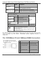
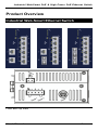
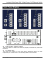
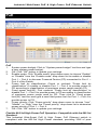
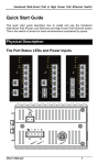
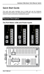
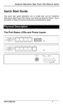
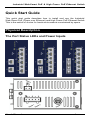
LED
Link/ACT
PoE
High Power PoE
State
Indication
Steady
A valid network connection established.
Flashing
Transmitting or receiving data.
ACT stands for ACTIVITY.
Steady
Power Device (PD) is connected.
Off
Power Device (PD) is disconnected.
Power Input Assignment
Power3
Power2
Power1
48, 55VDC (High Power)
+
48, 55VDC (High Power)
-
Power Ground
+
48, 55VDC (High Power)
-
Power Ground
DC Jack
Terminal
Block
Earth Ground
Relay Output Rating
0.1A @ 24VDC
Relay Alarm Assignment
FAULT
*Warning signal disable for following:
The relay contact closes if Power1 and Power2 are both
failed but Power3 on.
The relay contact closes if Power3 is failed but Power1
and Power2 are both on.
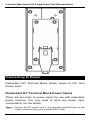
DC Terminal Block Power Inputs: There are two pairs of power inputs can be
used to power up this switch. Redundant power supplies function is
supported.
The 10/100Base-TX and 100Base-FX/BX Connectors
The 10/100Base-TX Connections
The following lists the pinouts of
10/100Base-TX ports.
2
Pin Regular Ports
Uplink port
1
Output Transmit Data + Input Receive Data +
2
Output Transmit Data - Input Receive Data -
3
Input Receive Data +
Output Transmit Data +
4
NC
NC
5
NC
NC
6
Input Receive Data -
Output Transmit Data -
7
NC
NC
8
NC
NC
User’s Manual