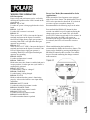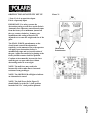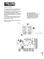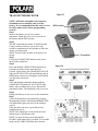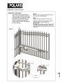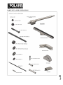
1
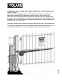
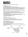
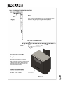
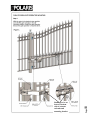
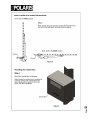
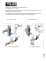
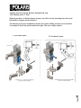
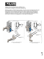
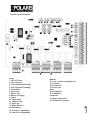
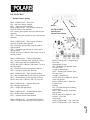
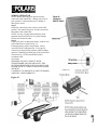
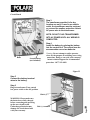
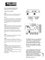
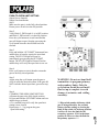
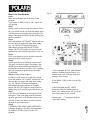
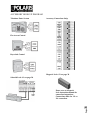
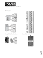
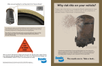
User Manual 500 & 700
Polaris 700/702
Polaris 500/502
Document revision: 1.1
Page
1
Warning: Before installing your Polaris
Automatic Gate operator (sometimes also
referred to as the “Product”), read this entire
Installation Manual for information about Product
safety matters and proper use of the Product.
Only use the Product for the purpose of
operating a driveway gate.
Table of Contents
Gate Operator Class Categories .............................................................................. 4
Warnings and Precautions ........................................................................................ 5
Installing The Polaris Operator(s)............................................................................. 8
Pull-to-Open Gate Operator Mounting ..................................................................... 9
Push-to-Open Gate Operator Mounting ................................................................. 11
Post Mount Brackets ............................................................................................... 13
Circuit Board Diagram ............................................................................................. 16
Board Layout Description ....................................................................................... 16
Dip Switches ............................................................................................................. 17
Wiring Operator ........................................................................................................ 18
Pull-to-Open Limit Setting ....................................................................................... 22
Push-to-Open Limit Setting ..................................................................................... 24
Primary/Secondary Gate Movement ....................................................................... 26
Obstruction Sensitivity Set Up ............................................................................... 27
Auto Close Timer ..................................................................................................... 28
Transmitter/Receiver ............................................................................................... 29
Accessory Hook Up Diagram .................................................................................. 30
Exit Wand Hook Up Diagram ................................................................................... 33
Photo Eyes Hook Up Diagram ................................................................................ 34
Emergency Disconnect ........................................................................................... 36
Technical Specifications ......................................................................................... 37
Parts List and Illustrations ...................................................................................... 38
Troubleshooting/Maintenance ................................................................................ 40
List of Accessories .................................................................................................. 42
Page
Polaris Automatic Gate Operators
8617 Paseo Alameda NE
Albuquerque, NM 87113
Phone: 877-313-8902
Fax: 800-830-3952
Email: [email protected]
Web: www.polarisgate.com
2
Warranty ................................................................................................................... 43
WARNING OF RISKS, PURCHASER’S RESPONSIBILITIES, AND ASSUMPTION OF
CERTAIN RISKS:
The directions for installation and use of the Product must be followed carefully. It is
impossible to eliminate all risks inherently associated with use of the Product. The
effectiveness of the Polaris Automatic Gate Operator depends on proper installation and
the manner of use or application, all of which are beyond the control of Polaris Professional
Products or the seller. All such risks are assumed by the purchaser, and by the purchaser’s
installation and use of the Product.
Page
3
The Polaris Automatic Gate Operator is for use on driveway gates only. The Product meets
or exceeds the requirements of UL 325, the standard that regulates gate operator safety, as
established and made effective March 14, 2003, by Underwriters Laboratories, Inc.
Gate Operator Class Categories
Gate operator CLASS CATEGORIES*
The Polaris Automatic Gate Operator is intended for use with vehicular swing gates. The
operator can be used in Class I and Class II applications.
Residential Vehicular Gate Opener–Class I: A vehicular gate opener (or system) intended
for use in a home of one-to-four single family dwelling, or a garage or parking area
associated therewith.
Light Commercial/General Access Vehicular Gate Opener Class II: A vehicular gate
opener (or system) intended for use in a commercial location or building such as a
multifamily housing unit (five or less single family units), hotel, garages, retail store or
other building servicing the general public.
Industrial/Limited Access Vehicular Gate Opener–Class III:
A vehicular gate opener (or system) intended for use in an industrial location or building
such as a factory or loading dock area or other locations not intended to service the general
public.
Restricted Access Vehicular Gate Opener–Class IV: A
vehicular gate opener (or system) intended for use in a guarded industrial location or
building such as an airport security area or other restricted access locations not servicing
the general public, in which unauthorized access is prevented via supervision by security
personnel.
*Categories established by Underwriters Laboratories for vehicle gate operators
Polaris is a high end residential gate operator. Also suited for light commercial
applications. Not advised for continuous duty.
4
Retailer/store name: __________________
Customer Service
8:00am to 5:00pm, MST, Monday – Friday
Polaris Gate Operators
8617 Paseo Alameda NE
Albuquerque, NM 87113
Phone: 877-313-8902 Fax: 800-830-3952
Email: [email protected]
Page
GATE OPERATOR CLASS CATEGORIES
FOR YOUR RECORDS
Please record the serial number
(found on the control box cover)
and purchase information below.
Keep this with your proof of purchase
(receipts) in case your product is lost, stolen
or requires service.
Serial number: _______________________
Purchase date: ____________________
Warnings and Precautions
The gate operator’s built-in means of entrapment
protection (Type A) may not be sensitive enough to
prevent bodily injury in some circumstances.
Secondary means of entrapment protection (Type
B1), such as a photo cell are suggested for enhanced
safety.
WARNING – To reduce the risk of injury or death:
• SAVE THESE INSTRUCTIONS
• Use this operator only with swing gates.
• READ AND FOLLOW ALL
INSTRUCTIONS.
• Never let children operate or play with gate
controls.
• Keep the remote control away from
children.
• Always keep people and objects away from the
gate.
• NO ONE SHOULD CROSS THE PATH
OF THE MOVING GATE.
• The entrance is for vehicles only.
Pedestrians must use a separate entrance.
• Remember that the Polaris Automatic Gate
Operator must only be installed on gate
systems meeting the requirements of the
application.
• Ensure that you are using the correct gate
operator for the type and size of gate, its
frequency of use and the class rating.
•
•
•
•
•
•
•
•
Ensure that the gate and gate operator
installation comply with applicable
local codes.
Contact local fire and law enforcement
to arrange emergency access
procedures.
Keep people, animals, and property
away from the gate area. Do not let
children play in or near the gate area.
Use caution with moving parts to avoid
injuring fingers or hands.
Consider installing contact sensors, or
non-contact sensors to provide
additional safety and protection against
entrapment.
Never activate the gate operator until
you ensure that the area is clear of
people, pets, or other obstructions.
Watch the gate until it stops.
Controls must be far enough from the
gate so that the user is prevented from
coming in contact with the gate while
operating the controls.
5
The Polaris Automatic Gate Operator is designed to
provide for safe operation. One of the most important
safety features of the gate operator is obstruction
sensing. When there is an obstruction that prevents
the gate from opening or closing, the gate will
immediately reverse direction and return to the fully
open or closed position. While in the process of
returning to the fully open or closed position, if the
gate senses an additional obstruction the gate will
stop immediately and sound an alarm. At this point
the gate operator will need to be reset by turning the
power switch on the control box OFF for a minimum
of ten seconds.
The Polaris gate operator includes an adjustment for
setting the sensitivity of the obstruction performance.
Refer to page 27 for Obstruction Sensitivity Set Up
details.
Vehicular gates are large heavy objects. Polaris
Automatic gate operators provide a convenient way
to open and close the gates. Since the gate system and
its components exert a high level of force to open and
close the gate, they can be dangerous, causing severe
injuries or death to you and others.
Your safety and the safety of others depend on the
installer of this system to read, understand, and
follow the information and instructions in this
manual.
The Polaris Automatic Gate Operator is designed to
comply with UL 325, the safety standard covering
automatic gate opening systems. UL 325 requires that
gate opening systems have provisions for, or be
supplied with, at least one independent primary and
one independent secondary means of protection
against entrapment. The primary means of
entrapment protection in the Polaris Automatic
Gate Operator is Type A, an inherent means of
entrapment protection. The secondary means of
entrapment protection in the Polaris Automatic Gate
Operator is Type B1, the provision for the connection
of a photo cell or other non contact sensor
Safety overview checklist:
Page
General Safety Information
Protection against Entrapment
Important! Study the figure below and keep safety foremost at all times.
Entrapment areas for a proper pull-to-open installation
Entrapment Area 1
Hinged edge of the gate and the fence post
Entrapment Area 2
Between the gate and the gate post
Entrapment Area 3
The path of the gate
Entrapment Area 4
The space between the gate in the open position and
any object such as a wall, fence, tree, etc.
Entrapment Area 5
Pinch points between the operator and gate or post
Area 1
Area 2
Area 5
Area 3
Area 4
Page
6
Driveway
Gate in open
position
Entrapment Alarm
Warning Signs and Labels
(UL 325; 30.1)
In compliance with UL 325 the Polaris
Automatic Gate Operator is designed to
stop and reverse direction within two
seconds of sensing an obstruction. In
addition, the Polaris Automatic Gate
Operator activates an audible alarm if the
unit incurs an obstruction twice while
opening or closing. This alarm sounds for
five minutes, or until the operator receives
a renewed, intended input from a
hardwired control such as the Push Button
Control. At that point the gate returns to a
fully open or fully closed position. Turning
the power switch on the control box OFF
for ten seconds and back ON also
deactivates the alarm.
Required Safety Precautions for Gates
Warning signs alert people of automatic
gate operation. They are required when
installing the Polaris Automatic Gate
Operator. If pedestrians will be in the area,
install a walkthrough gate for their use.
Warning Signs
The warning signs must be installed on
both sides of the gate.
These warning signs and decals must be
used. If any
were missing when the gate operator was
purchased,
immediately contact Polaris Automatic
Gate Operators for replacements.
Figure 2
Warning signs (two enclosed) to be
installed on each side of the gate
(three to five feet above the bottom
of the gate)
Figure 3
Page
7
Install warning decals,
one on each side of gate
operator
INSTALLING THE POLARIS 500 & 700 SWING OPERATOR
WARNINGS--------------------1. Read and follow all instructions.
2. NEVER let children operate the gate or play with the controls.
3. Keep people and objects away from the gate and its immediate areas, both open and closed.
4. After the limit adjustments are made, all auto reversing controls including the current
sensing circuit built into the Polaris must be checked. They must be working and set to proper
sensitivity. Failure to adjust and retest the gate system increases the chance of injury or
death.
5. Test the system MONTHLY. Check to make sure that all auto-reversing devices including
the current sensing circuit are working and set to the proper sensitivity.
6.Verify that the emergency (manual) release pin connected to the gate leaf can be easily
removed. This check should only be made with the battery disconnected to prevent the gate
from moving during the test.
7. This is a VEHILCLE GATE ONLY. Pedestrians must use a separate entrance.
8. NEVER install any control device on the outside of the Polaris cabinet or in such a way that
someone can reach through the gate to activate it.
9. SAVE THESE INSTRUCTIONS!
CAUTIONS----------------------1. NEVER operate the gate unless you can see it.
2. Do not enter the gate area while the gate is in motion.
3. Do not allow children near the gate and do not allow anyone to ride on the gate.
4. Do not attempt to drive through the gate opening while the gate is in motion.
Page
8
ENTRAPMENT ZONES--------------------Zone 1- Leading edge of the gate and catch-post
Zone 2- Area between gate and hinge post.
Zone 3- The gate path or "arc of the swing"
Zone 4- The area between the gate in its' open position and any obstruction like a fence,
building, landscaping feature, etc...
Zone 5- Not shown below but similar to zone 1- the point where two biparting gate leafs meet
when closed.
9
Page
10
Page
11
Page
Bushings to be set
between bottom
side of actuator
rod ends and
mounting bracket
12
Page
Amazing Gates Post Mount Brackets Pull and Push Arm
with Amazing Gates 3 1/2" Posts
With the purchase of a Polaris Opener System, you will receive the Amazing Gates Universal
Pull brackets and gate attach bracket(s).
The Amazing Gates post attachment arm does not require drilling of the post to be installed.
You simply set it into the position and bolt it tight. The correct angle is preset.
13
3 1/2" Post Push to Open
Page
3 1/2" Post Pull to Open
Amazing Gates Post Mount Brackets Pull and Push Arm
with Amazing Gates 5" Posts
With the purchase of a Polaris Opener System, you will receive the Amazing Gates Universal
Pull brackets and gate attach bracket(s).
The Amazing Gates post attachment arm does not require drilling of the post to be installed.
You simply set it into the position and bolt it tight. The correct angle is preset.
14
5" Post Push to Open
Page
5" Post Pull to Open
Amazing Gates Post Mount Brackets Pull/Push Arm
with customers existing Posts other than Amazing Gates.
Page
15
With the purchase of a Polaris Opener System, you will receive the Amazing Gates Universal
Pull and Push brackets and gate attach bracket(s). These brackets can be used with your
exiting posts or any non-Amazing Gates posts, to include column mounting. Though the
Amazing Gates bracket system can be used on any post/column setup, the diagram shown
below must be followed concerning geometry of pivot point and hinge point.
Board Layout Description
16
Buttons
16. Cycle – used as an input device
17. Set Limit
18. Learn Code
19. Power Save
Fuses
20. 15 amp Fuse
21. 4 amp Fuse
Connectors
22. Buzzer Connection
23. RF Board Connection
Page
LED’s
1. 18 VAC Power
2. 24V Converter
3. Gate Operator Retracting
4. Gate Operator Extending
5. Obstruction
6. Auto Close
7. Battery OK
8. Battery Charging
9. Status
10. Safety Loop
11. Shadow Loop
12. Exit Loop
13. Radio Receiver
Potentiometers
14. Stall Force Adjustment
15. Auto Close Adjustments
DIP SWITCHES
* - Default factory setting
Block 1, DIP Switch 1 – Auto Close
ON – Auto close feature enabled
OFF* – Auto close feature disable
Block 2, DIP Switch 2 – Pull-to-Open or Push-toOpen for Primary Gate Operator
ON – Primary gate operator set up for push-to-open
operation
OFF* – Primary gate operator set up for pull-to-open
operation
Block 1
Block 2
NOTE: All DIP
Switches are
shown in the factory
Block 2, DIP Switch 3 – Pull-to-Open or Push-toOpen for Secondary Gate Operator
ON – Secondary gate operator set up for push-toopen operation
OFF* – Secondary gate operator set up for pull-toopen operation
NOTE: Only active if Block 2, DIP Switch 1 is set in
the ON position
Block 2, DIP Switch 1 – Single or Dual Gate
ON – Dual gate applications
OFF* – Single gate applications
Block 1, DIP Switch 2 – Audible Motion Alarm
ON – Audible motion alarm enabled
OFF* – Audible motion alarm disabled
Block 1, DIP Switch 3 – Extended Soft Start/Stop
NOTE: To adjust auto close time refer to figure 17.
17
Block 1, DIP Switch 4 – Time of Soft Start/Stop
ON – Max. extended time of soft start/stop operation
OFF* – Extended time of soft start/stop operation
NOTE: Only active if Block 1, DIP 3 is set to ON
Block 2, DIP Switch 5 – Sequencing of
Dual Gate
Opening and Closing
ON – Secondary gate operator opens
first and closes
second (2 second delay)
OFF* – Primary gate operator opens
first and closes
second (2 second delay)
NOTE: Only active if Block 2, DIP 4 is
in the ON position
Block 2, DIP Switch 6 – Dual Gate
Position Limit
Settings
ON – Set limit setting for secondary
gate operator
OFF* – Set limit setting for primary
gate operator
NOTE: Only active if Block 2, DIP
Switch 1 is set in the
ON position
Block 2, DIP Switch 7 – Off - Not Used
Block 2, DIP Switch 8 – Off - Not Used
Page
Block 2, DIP Switch 4 – Timing of Dual Gates
ON – One gate is delayed when opening or closing
OFF* – Gates open and close simultaneously
NOTE: Only active if Block 2, DIP Switch 1 is set in
the ON position
ON – Extended soft start/stop operation enabled
OFF* – Normal soft start/stop operation
WIRING OPERATOR
NOTE: Before powering, gate operator must be
connected to the control box – damage may occur if
gate operator is connected directly to a battery or
other power source.
Step 1
Ensure the control box power switch is in the OFF
position. The control box power switch is located on
the bottom of the control box.
NOTE: Use only 16 gauge dual conductor, multistranded, direct burial wire for AC power hookup.
Follow local electrical codes.
Step 2
If using AC power to charge the battery, connect wire
to the control box as shown in fig. 19.
If charging battery with a solar panel(s), refer to
Accessory Hook-Up Diagram fig. 32 on page 28.
Connect wires from primary operator (and secondary
operator if installing on a dual gate) to the control box
as shown in fig. 19. Wire should be buried in
accordance with
local codes.
WARNING: DO NOT CONNECT BOTH
TRANSFORMER AND SOLAR PANEL. THIS
SYSTEM IS DESIGNED TO RUN ON ONLY ONE
POWER SOURCE. CONNECTING BOTH POWER
SOURCES
CAN RESULT IN DAMAGE TO CIRCUIT BOARD
AND WILL VOID WARRANTY.
Page
18
Figure 19
Circuit Board
Step 3
The transformer provided is for dry
location use only. If used in an outside
outlet, the transformer must be enclosed
or covered for weather protection. Attach
AC power wire to the transformer.
NOTE: DO NOT PLUG TRANSFORMER
INTO AC POWER UNTIL ALL WIRING IS
COMPLETED.
Step 4
Install the battery by placing the battery
into the control box. The control box can
accommodate one or two batteries.
Batte
Second Battery
(not included)
Warning: Do not attempt to splice operator
wires for the purpose of extending your wiring
connections. Doing so can void your warranty.
Contact technical support for recommended
procedure. 1-877-313-8902.
Figure 22
Step 5
Connect the battery terminal
wires to the battery.
Step 6
Plug in transformer. Turn control
box power switch to the ON position.
Red (+) terminal
Page
WARNING: Please make sure
the batteries are fully charged
before connecting and powering
up the new circuit board.
Undercharged batteries may
damage the circuit board and
void your warranty.
19
Black (-)
Polaris Automatic Gate Operators come equipped
with a Power Save feature. The default mode is for all
LED’s to be operational as described. If it is desired
to conserve power to maximize battery life
Recommended for the following steps can be taken.
Press and hold the PWR SAVE button for three
seconds. An audible beep will sound confirming the
change to the power save mode. This will disable
several LED’s when not activated for five minutes. In
Power Save mode, the LED’s will operate as
described upon an input. When the gate sits idle for
five minutes, the LED’s will turn off to conserve
power.
When troubleshooting the installation it is
recommended to disable the Power Save feature. The
feature can be disabled by pressing and holding the
PWR SAVE button for three seconds. Two audible
beeps will sound confirming the change to normal
mode operation.
20
LED Descriptions
Proper wiring and performance can be verified by
checking the operation of the LED’s located on the
circuit board.
LED #1: 18VAC OK
Lit when AC power is being supplied to the circuit
board.
LED #2: +24V OK
Lit when 24V converter is activated.
LED #3: IN
There are two “IN” LED’s. One near the Opener 1
terminals and one near the Opener 2 terminals.
One LED will light when a single gate operator is
retracting. Both LED’s will light when dual gate
operators are retracting.
LED #4: OUT
There are two “OUT” LED’s. One near the Opener 1
terminals and one near the Opener 2 terminals. One
LED will light when a single gate operator is
extending. Both LED’s will light when dual gate
operators are extending.
LED #5: OBSTR
Lit when an obstruction is sensed.
LED #6: TIMER ON
Blinks when auto close feature is enabled and gate is
in open position. Lit when gate arm cycle limiter is
automatically activated.
LED #7: BATT OK
Lit when battery is OK or “charged.”
LED #8: CHARGING
Lit when battery is being charged.
LED #9: STATUS
Blinks to indicate that the system is functioning
properly. Also used to indicate a user input during
installation.
LED #10: SAFETY LOOP
Lit when the safety loop contact is made.
LED #11: SHADOW LOOP
Lit when shadow loop contact is made.
LED #12: EXIT LOOP
Lit when an exit loop contact is made.
LED #13: RADIO RECVR
Lit while transmitter button is pushed.
Power Save Mode (Recommended for Solar
Applications)
Page
WIRING THE OPERATOR
Page
21
WIRING THE OPERATOR
PULL-TO-OPEN LIMIT SETTING
(Open gate to inside of property)
Single Gate Installations
Step 1
Make sure the gate is in the fully open position.
Ensure power switch is in the ON position.
Step 2
Verify Block 2, DIP Switch #1 is in OFF position.
Press the cycle button on circuit board and the
gate will begin to close. Stop the gate using the
cycle button when the desired limit has been
reached.
Step 3
Press and hold the “SET LIMIT” button until one
audible beep is heard to acquire the closed limit
setting. The STATUS light will turn on
immediately upon pressing the SET LIMIT
button. The STATUS light will turn off and an
audible beep will verify the closed limit is now
set.
Step 4
Press cycle button on circuit board to return the
gate to the fully open position.
***Dip switch number 6 dictates which
gate is being affected by the set limit
button, whether setting or clearing the
limit. If dip switch 6 is in the up position,
it will set or clear the limit for the
secondary operator. If it’s in the down
position it will set or clear the limit for
the primary operator.***
22
Step 6
CLEARING THE CLOSED LIMIT SETTING:
a) Return the gate to the fully open position.
b) Press and hold the SET LIMIT button until two
audible beeps are heard.
c) Two audible beeps will verify the closed limit
setting is now cleared.
Repeat steps 1 – 5 to program the gates “closed
limit setting”.
WARNING: Do not use hand held
transmitters to program primary
and secondary limits. Only the
cycle button should be used until
final set up is complete to avoid
damage to actuators and voiding
warranty.
Page
Step 5
Again, using the cycle button close the gate to
verify it meets the desired location. If the gate did
NOT reach the desired closed limit, proceed to
step 6.
23
Step 8
CLEARING THE CLOSED LIMIT SETTINGS:
a) Return the gates to the fully open position.
b) Set Block 2, DIP switch #6 to the OFF position.
c) Press and hold the SET LIMIT button until two
audible beeps are heard. Two audible beeps will
verify the closed limit setting is now cleared.
d) Set Block 2, DIP switch #6 to the ON position.
e) Press and hold the SET LIMIT button until two
audible beeps are heard. Two audible beeps will
verify the closed limit setting is now cleared.
Repeat steps 1 – 7 to program the gates “closed
limit setting”.
Page
PULL-TO-OPEN LIMIT SETTING
Dual Gate Installations
Step 1
Make sure both gates are in the fully open
position.
Ensure power switch is in the ON position.
Step 2
Verify Block 2, DIP Switch #1 is in ON position.
Press the cycle button on the circuit board and the
gates will begin to close. Stop the gates using the
cycle button when the desired limit for the
primary gate has been reached.
Step 3
Verify Block 2, DIP Switch #6 is in the OFF
position. Press and hold the “SET LIMIT” button
until one audible beep is heard to acquire the closed
limit setting(fig. 28).The STATUS light will turn on
immediately upon pressing the SET LIMIT button.
The STATUS light will turn off and an audible beep
will verify the closed limit is now set.
Step 4
Press the cycle button on circuit board to return
the gates to the fully open position.
Step 5 (setting secondary gate)
Set Block 2, DIP switch #6 to the ON position.
Again, press the cycle button. The gates will
begin to close. The primary gate should stop at the
closed limit position that was programmed in the
previous steps. The secondary gate will continue
to close until you press the cycle button on the
circuit board.
Step 6
Press and hold the “SET LIMIT” button until one
audible beep is heard to acquire the closed limit
setting (fig. 28). The STATUS light will turn on
immediately upon pressing the SET LIMIT
button. The STATUS light will turn off and an
audible beep will verify the closed limit is now
set.
Step 7
Press the cycle button on circuit board to open
both gates. Then once again press the button to
close the gates and verify the closed limits are set
properly. If the gates did not reach the desired
closed limits, proceed to Step 8.
PUSH-TO-OPEN LIMIT SETTING
(Open Gate to Outside)
Single Gate Installations
Step 1
Make sure the gate is in the fully closed position.
Ensure power switch is in the ON position.
Step 2
Verify Block 2, DIP Switch #1 is in OFF position
and Block 2, DIP switch 2 is in the ON position.
Press the cycle button on circuit board and the
gate will begin to open. Stop the gate using the
cycle button when the desired limit has been
reached.
Step 3
Press and hold the “SET LIMIT” button until one
audible beep is heard to acquire the open limit
setting. The STATUS light will turn on
immediately upon pressing the SET LIMIT
button. The STATUS light will turn off and an
audible beep will verify the open limit is now set.
Step 4
Press cycle button on circuit board to return the
gate to the fully closed position.
***Dip switch number 6 dictates which
gate is being affected by the set limit
button, whether setting or clearing the
limit. If dip switch 6 is in the up position,
it will set or clear the limit for the
secondary operator. If it’s in the down
position it will set or clear the limit for
the primary operator.***
24
Step 6
CLEARING THE OPEN LIMIT SETTING:
a) Return the gate to the fully closed position.
b) Press and hold the SET LIMIT button until two
audible beeps are heard.
c) Two audible beeps will verify the open limit
setting is now cleared.
Repeat steps 1 – 5 to program the gates
“open limit setting”.
WARNING: Do not use hand held
transmitters to program primary
and secondary limits. Only the
cycle button should be used until
final set up is complete to avoid
damage to actuators and voiding
warranty.
Page
Step 5
Again, using the cycle button open the gate to
verify it meets the desired location. If the gate did
NOT reach the desired open limit, proceed to step
6.
c) Press and hold the SET LIMIT button
until two audible beeps are heard. Two
audible beeps will verify the open limit
setting is now cleared.
d) Set Block 2, DIP switch #6 to the ON
position.
e) Press and hold the SET LIMIT
button for until two audible beeps are
heard. Two audible beeps will verify the
open limit setting is now cleared.
Repeat steps 1 – 7 to program the gates
“open limit setting”.
25
Step 1
Make sure both gates are in the fully closed
position.
Verify Block 2, DIP Switch #1,2 & 3 are in the
ON position,
Step 2
Ensure power switch is in the ON position. Press
the cycle button on the circuit board and the gates
will begin to open. Stop the gates using the cycle
button when the desired limit for the primary gate
has been reached.
Step 3
Press and hold the “SET LIMIT” button until you
hear one beep to acquire the open limit setting
(fig. 29). The STATUS light will turn on
immediately upon pressing the SET LIMIT
button. The STATUS light will turn off and an
audible beep will verify the open limit is now set.
Step 4
Press cycle button on circuit board to return the
gates to the fully closed position.
Step 5
Again, press the cycle button on circuit board.
The gates will begin to open. The primary gate
should stop at the open limit position that was
programmed in the previous steps. The secondary
gate will continue to open until you press the
cycle button.
Step 6 (setting secondary gate)
Set Block 2, DIP switch #6 to the ON position.
Press and hold the “SET LIMIT” button until you
hear one beep to acquire the open limit setting
(fig. 29). The STATUS light will turn on
immediately upon pressing the SET LIMIT
button. The STATUS light will turn off and an
audible beep will verify the open limit is now set.
Step 7
Press the cycle button on circuit board to close
both gates. Then once again press the button to
open the gates and verify the open limits are set
properly. If the gates did not reach the desired
open limits, proceed to step 8.
Step 8
CLEARING THE OPEN LIMIT SETTINGS:
a) Return the gates to the fully closed position.
b) Set Block 2, DIP switch #6 to the OFF
position.
Fig.29
Page
Dual Gate Installations
PRIMARY/SECONDARY GATE
MOVEMENT
For dual gate installations the timing of the
gates opening and closing can be adjusted. To
set a dual gate installation for both gates to
open and close simultaneously, set the DIP
switches as follows.
Block 2, DIP 1 – ON position
Block 2, DIP 4 – OFF position
If it is desired to have one gate open and close
prior to the other, this can be accomplished by
adjusting the DIP switch settings.
Block 2, DIP 1 – ON position
Block 2, DIP 4 – ON position
Now determine which gate is desired to open
first and close second. Another DIP switch
adjustment is required to set this.
For primary gate operator (wired to operator 1
terminals) to open first and close second:
Block 2, DIP 5 – OFF position
For secondary gate operator (wired to operator
2 terminals) to open first and close second:
Block 2, DIP 5 – ON position
The delay in opening and closing is always set
for two seconds.
PRIMARY/SECONDARY GATE
MOVEMENT
Page
26
Control Box Cover
Once you have programmed your
remote/keypad, you can then install the cover
of the control box. Use five #10 x 3/4” screws to
secure the cover to the control box.
OBSTRUCTION SENSITIVITY SET UP
Figure 31
* Note: Cycle is an open/close input.
Exit is a open only input.
IMPORTANT: For safety reasons the
obstruction setting or stall force on the Polaris
Automatic Gate Operator control board comes
from the factory set at minimum, (turned all
the way counter-clockwise). In many gate
installations, this setting will need to be
adjusted to overcome the weight and size of the
gates.
The STALL FORCE potentiometer on the
circuit board controls the obstruction
sensitivity (or the amount of force the operator
will apply to an obstruction) before it
automatically stops and reverses direction of
the gate. Adjust the sensitivity beginning at the
factory default counter-clockwise position.
Continue to incrementally increase the force
until the gate can open and close without
obstructing under its own weight.
Obstruction
Potentiometer
NOTE: The stall force may need to be
increased in cold weather due to increased
resistance from gate hinges.
NOTE: The OBSTR LED will light to indicate
an obstruction is sensed.
Page
27
NOTE: The Stall Force dial in Figure 31
should ideally be at the 10 o’ clock position
instead of the 12 o’ clock position pictured.
Auto Close Timer
The amount of time between opening the gate
and automatically closing the gate can be
adjusted between 0 seconds and 120 seconds.
The adjustment is made by turning the
CLOSE TIMER potentiometer. The default
position of the potentiometer is zero seconds.
Timer will
activate after gates have completed one full
cycle. To increase the delay time, turn the
potentiometer clockwise.
POLARIS STRONGLY
RECOMMENDS THE USE OF A
SAFETY DEVICE SUCH AS:
PHOTO BEAMS OR SAFETY
LOOP WHEN AUTO CLOSE
TIMER IS ACTIVATED!
Page
28
NOTE: Only active if Block 1, DIP switch 1 is
in the ON position.
DIP Switches
Transmitter
Figure 26
29
NOTE: All Polaris Automatic Gate Operator
transmitters use a standard code set at the
factory. It is recommended that this code is re-set
for safety and security before programming
receiver.
Step 1
Remove the battery access cover on the
transmitter. When the cover is off, you will see
the battery and the DIP switches.
Step 2
The DIP switch block contains 10 small switches.
Using a small screwdriver or pen, move any
switch or combination of the switches to either the
open or closed position.
NOTE: Do not set the switches to all open or all
closed.
Step 3
Locate the LEARN CODE button on the circuit
board in the control box.
Step 4
Press and hold the LEARN CODE button for at
least three seconds, but no more than five
seconds. Upon release, the CHARGING LED will
light, the STATUS LED will stop blinking, and an
audible beep will occur verifying the circuit board
is in the learn code mode.
Step 5
Press and hold the transmitter button until the
CHARGING LED turns off, the STATUS light
blinks, and an audible beep occurs. Release the
transmitter button. The transmitter code is now set.
Step 6
Replace the battery access cover on the transmitter.
Step 7
Verify the transmitter is operational by pressing
the transmitter button. The RADIO RECEIVER LED
will light and the gate will move if the setting is
correct.
If the gate does not move, repeat the process
starting with step 4.
NOTE: The control box circuit board can learn
and hold up to 10 different codes.
NOTE: To clear all codes, press and hold the
LEARN CODE button for 10 seconds. Two audible
beeps verify LEARN CODE has been cleared.
Figure 25
Page
TRANSMITTER/RECEIVER
Page
30
* Note: Some accessories may require additional wire and/or hardware and is to be supplied by the
installer.
ACCESSORY HOOK UP DIAGRAM
Telephone Entry System
Accessory Connections Strip
Fire Access Control
Keyswitch Control
Magnetic Lock- #2 see page 30
Solenoid Lock- #1 see page 30.
Page
31
Please refer to Magnetic
Lock instruction manual for
connection instructions.
Connections differ for 12v or
24v connection.
ACCESSORY HOOK UP DIAGRAM
Wired Keypad
Photo Eye Beams
32
External Radio Receiver
Page
Victory PB-1200 Photo Eye Beams
Page
33
EXIT WAND HOOK UP DIAGRAM
PHOTO EYE HOOK UP DIAGRAM
NIR Photo Eye
The NIR photo-eye has two parts: the EMITTER and the REFLECTOR. The
EMITTER has 5 screw terminals labeled by color. Attach the terminals in the emitter
to those on the gate operator circuit board as shown below. Use a direct-burial type of
control wire like "sprinkler wire" and position the emitter on the hinge-side of the
Brown
Gray
White
Black
Blue
*Black wire not used*
Page
*Use these instructions in combination with the NIR
instructions that come with the photo eyes.*
34
NIR Photo
PHOTO EYE HOOK UP DIAGRAM
IRB 4X Photo Eye
Page
*Use these instructions in
combination with the IRB 4X
instructions that come with the
35
The IRB 4X photo-eye has two parts: the TRANSMITTER and the RECEIVER. The
TRANSMITTER has 2 screw terminals labeled plus and minus. The RECEIVER has 5
terminals, DO NOT use terminal #4. To connect the units to the gate operator circuit
board, see the drawing below. Use a direct-burial type of control wire like "sprinkler
EMERGENCY DISCONNECT
Page
36
CAUTION: The gate will move
freely and uncontrolled when the
gate operator is removed from the
gate. ONLY disconnect the gate
operator when the control box
power switch is OFF and the gate
is NOT moving.
TECHNICAL SPECIFICATIONS
Mechanical Specifications
Electrical Specifications
Motor: 24 VDC
Voltage Ratings:
Powered by a 24 v VDC motor
18 VAC transformer: 18.0 to 22.0 VAC
12 V Battery: 12.0 to 13.5 VDC 7.2Ah
Charging Circuit: 12.0 to 14.8 VDC
Shipping Weight: POLARIS 500: 65 lbs
POLARIS 500/502: 88 lbs
POLARIS 700: 65 lbs
POLARIS 700/702: 90 lbs
Transmitter/Receiver Frequency: 433MHz
Travel Speed: 16 seconds for 90° (opening
under normal conditions and normal load)
Transmitter Range: Up to 100 feet (90
meters) *varies greatly depending on gate
surroundings
39.6 inches retracted
58.6 inches extended
POLARIS 500/502
Capacity
Stroke Length
Minimum Gate Length
12 feet/200 pounds
19 inches
60 inches
44.6 inches retracted
68.6 inches extended
37
14 feet/300 pounds
24 inches
72 inches
Page
POLARIS 700/702
Capacity
Stroke Length
Minimum Gate Length
Page
38
PARTS LIST AND ILLUSTRATIONS
PARTS LIST AND ILLUSTRATIONS
Secondary Gate Operator
40 ft. cable
Polaris 502
Polaris 702
Circuit Board
Cabinet Dimensions:
14.5h x 12.5w x 6.5d
Control Box
Transformer
Page
39
Battery
TROUBLE SHOOTING
The gate will not operate using the handheld
transmitter.
1. Press transmitter button to verify LED on
transmitter illuminates. If not, replace 9V battery.
2. Observe "radio receiver led" on the control
board and verify it turns on when transmitter
button is pressed. If so,the transmitter is working
correctly refer to troubleshooting section “The Gate
Will Not Operate.” If the LED does not illuminate,
proceed to step 3.
3. Refer to page 22 of manual “Transmitter/Receiver”
and relearn the transmitter code. If the problem still
exists proceed to step 4.
4. Verify RF Board Connection.
If connections are correct, please call technical
support.
The Gate Will Not Close Automatically
1. Make sure dip switch 1, block 1 is in the on
position.
2. Adjust timer to preferred close time.
3. Gate must complete one full cycle before timer is
activated.
1. Verify power switch is on.
2. Verify the STATUS LED is blinking
approximately once per second. If not, check
battery connections and both 4A and 15A fuses.
3. Verify SAFETY LOOP LED, SHADOW
LOOP LED and EXIT LOOP LED are not on. If
any of these are on, try disconnecting the
corresponding device.
4. If using an AC power source, verify the 18VAC
LED is on.
5. Verify the 12V battery voltage. If below 12.3V,
then replace or recharge the battery.
6. Clear and redefine limits as described earlier in
the manual.
7. Try the CYCLE button on the control board.
8. Verify all connections especially the actuators.
9. Verify FIRE BOX, PHOTO BEAMS, or EXIT
WAND (if installed) is not preventing gate
movement.
The gate(s) are operating slowly.
1. This is usually due to low power. Check voltage
on batteries. If voltage is below 12.3V, allow time
for batteries to charge before operating gates. (if
this is a solar application and there has been a lack
of sunlight, you will need to charge batteries with
a trickle charger before operating your gate(s).)
The status light is flashing rapidly.
1. This is also most likely due to a power problem.
Check battery voltage and charge batteries if
necessary.
2. After batteries are fully charged, power down
system for 5 seconds and turn back to on position.
There are no remaining inputs for 12vdc for my
accessories.
1. You may create a pigtail connection and
connect more than one accessory to a 12vdc input
connector.
Can I adjust the actuator manually to fit my
gate?
1. No. The actuator must be installed in the fully
retracted position and connected to the gate attach
bracket at that point. Please refer to page 10 for a
pull-to-open application or page 12 for a push-toopen application.
40
1. Verify the gate frame is not encountering an
obstruction and the gate hinges are not binding.
2. If the OBSTR LED is lit, the stall force may be set
too sensitive. Increase the stall force by
turning the STALL FORCE potentiometer clockwise
1/8 turn. Operate the gate again to see if the problem
still exists.If the problem still exists increase the stall
force again and retry. If the problem still exists procee
to step 3.
CAUTION: Increasing the stall force reduces
obstruction protection.
3. Reset the operator by turning the power off for
five seconds. Turn the power back on and press the
CYCLE button and allow the operators to fully
retract.Try operating the gate again to see if the
problem still exists. If the gate stops before reaching
the desired position, clear and redefine the limit
settings as described earlier in the manual.
4. Check for any loose or incorrect connections.
5. If steps 1–4 did not solve the problem please
call technical support at 1-877-313-8902.
The gate(s) will not operate.
Page
The gate(s) stops or reverses before reaching
the desired position.
TROUBLE SHOOTING
MAINTENANCE
The 15 amp fuse is blown.
Preventive Maintenance
• Using a clean, dry cloth, wipe the gate
operator shaft, and then apply a silicone
spray. The silicone spray will reduce friction
in extreme temperature ranges and help the
gate operator operate smoothly. This should
be repeated every 4–6 weeks. If needed, spray
a small amount of silicone lubricant into tiny
pinhole found on shaft of actuator with
actuator in extended position.
• Check the gate hinges to make sure gate is
swinging smoothly and freely. Grease hinges
if needed.
• Check batteries occasionally for corrosion
and clean leads if necessary. Check voltage
occasionally.
• In some cold weather climates it is
recommended to purchase battery heaters to
ensure that your batteries maintain a charge
throughout cold weather months. In this case,
battery heaters need to be unplugged during
spring, summer and fall months to prevent
overheating.
• For optimal performance, it’s recommended
that new batteries be installed annually.
1. Check wiring from transformer to circuit board.
2. Check for any loose or incorrect connections.
3. Check battery connections for any corrosion or
loose wires.
4. After replacing fuse, verify that 18vac light is
illuminated. (this is not valid on a solar powered
system.)
5. Call technical support if fuse blows again.
How do I reset the limits on my gate(s)?
1. Make sure you start with both arms in the fully
retracted position.
2. Clear the limits on both arms by pressing the set
limit button and holding it in until it beeps twice.
Set dip switch 6 in the opposite position and press
set limit again until it beeps twice. You have now
cleared the limits for both operators.
3. Dip switch number 6 dictates which gate is
being affected by the set limit button, whether
setting or clearing the limit. If dip switch 6 is in
the up position, it will set or clear the limit for the
secondary operator. If it’s in the down position it
will set or clear the limit for the primary operator.
4. Once limits have been cleared, cycle the gates
to (close- pull to open) or (open- push to open)
and stop the gates using the cycle button when a
gate gets to the desired closed/open position. Once
this occurs set the limit for that gate by pressing
the set limit button until it beeps once. (make sure
dip switch 6 is set appropriately) Cycle the gates
back to the open/ closed position.
5. With the gates in the open/closed position,
cycle gates to close/open once again. This time
stop the gates when the other gate gets to the
desired stop location. Once that is accomplished,
set the limit for that gate by setting the dip switch
6 correctly and pressing the set limit button until it
beeps once.
Customer Service
8:00am to 5:00pm, Mountain Time
Monday – Friday
Polaris Gate Operators
8617 Paseo Alameda NE
Albuquerque, NM 87113
Phone: 877-313-8902
Fax: 800-830-3952
email: [email protected]
41
The 4 amp fuse is blown.
Page
1. Check wiring from actuator arms to circuit
board for loose or cut connections.
2. Verify that all wiring is correct according to
page 18.
3. Check for any overheating or singed wiring.
4. Call technical support at 1-877-313-8902 before
attempting to replace fuse so as to prevent any
further damage.
LIST OF ACCESSORIES
Solar Powered Battery Charger (20-Watt: RSP20) The solar panel charges
the 12 volt battery when AC power is not available.
One-Button Transmitter. The transmitter works as an input device allowing
the user to open or close the gate from a remote location. It has a range up to
100 feet.
Two-Button Transmitter. The two-button transmitter provides the capability
to remotely operate two separate devices such as two gates, or a gate and a
garage door opener. It has a range up to 100 feet.
Mini-transmitter. The mini-transmitter fits on a keychain and allows the user
to open or close the gate from a remote location. It has a range up to 100 feet.
Keypad. The keypad allows for entry by authorized guests informed of the
pre-set code. Entering the correct code causes the gate to open or close. The
access code can be easily modified.
Pin Lock. The pin lock replaces the clevis pin when mounting the gate
operator to the brackets. It helps to prevent theft of the gate operator from the
gate, while allowing quick release of the operator.
In-Ground Vehicle Sensor. The vehicle sensor is buried near the gate and
senses a vehicle that passes within its 12-foot range. Once detected, the gate
opens automatically.
Page
Magnetic Gate Lock. The automatic gate lock provides an additional level of
security for the property. When the gate swings shut, the gate lock closes,
securing the gate in the closed position. The gate lock is powered from an
external AC power source. The locking mechanism is magnetic.
42
Solenoid Gate Lock. The automatic gate lock provides an additional level of
security for the property. When the gate swings shut, the gate lock closes,
securing the gate in the closed position. The gate lock is powered from the
control box of the gate operator. The locking mechanism is a mechanical latch.
Two Year Limited Warranty
Limited Warranty Coverage
If your Polaris Gate Operator (sometimes also referred to as
the “Product”) does not work properly because of a defect in
materials or workmanship, Polaris Gate Operators will, for the
length of the period indicated below, which starts with the date
of the original purchase by the first non-consumer purchaser
(the “Limited Warranty period”), at its option either (a) repair
your Product with new or refurbished parts, or (b) replace it
with a new or a refurbished Product. The decision to repair or
replace will be made by Polaris Gate Operators.
Parts Labor
Two (2) Years
Labor
Two (2) Years
During the “Labor” Limited Warranty period there will be no
charge for labor. (Note: labor applies only to the repair of the
Product at an Authorized Repair Center. It does not apply to
removal or installation of the Product any purchaser’s
premises). During the “Parts” Limited Warranty period, there
will be no charge for parts.
You must ship your Polaris Gate Operator to Polaris Gate
Operators during the applicable Limited Warranty period. This
Limited Warranty excludes both parts and labor for batteries,
antennas, and cosmetic parts (such as the Product housing).
This Limited Warranty only applies to Products purchased in
the United States. This Limited Warranty is extended only to
the original non-consumer purchaser (“you” or “your”) of a
new Product that was not sold “as is”.
Limited Warranty Service
For assistance in the continental U.S.A. in obtaining the
benefit of the Limited Warranty please carefully follow these
steps:
1) Complete carefully all troubleshooting procedures in the
Maintenance and Troubleshooting Guide in this Manual.
2) If you are still unable to solve the problem, contact Polaris
Gate technical support at [email protected].
Please have the model and serial number of the Product
available to give to the customer service representative. The
customer service representative will provide further assistance
or authorize repair or replacement, as appropriate.
3) If repair or replacement is appropriate you will be given a
return authorization number (RMA#). This RMA# must be
visible on all documents and packages returned to Polaris Gate
Operators.
4) Carefully pack the defective Product or Product part in a
sturdy shipping carton, include (i) a letter detailing the
complaint, (ii) a daytime phone number where you can be
reached, (iii) your name and address for any return, (iv) your
sales receipt/proof of purchase, and (v) the RMA# on all
correspondence and the shipping carton.
43
You may obtain additional copies of this manual from our web
site at www.polarisgate.com, or contact Polaris Gate Operators
at: 8617 Paseo Alameda NE Albuquerque NM 87113,
877-313-8902.
Page
WARRANTY
5) Prepay the freight and insure the defective Product or
Product part against shipping damage. Note that defective
Products or Product parts shipped freight collect will not
be accepted.
6) Ship the carton to: Polaris Gate Operators, 8617 Paseo
Alameda NE, Albuquerque, NM 87113.
IF REPAIR OR REPLACEMENT IS NEEDED
DURING THE LIMITED WARRANTY PERIOD,
YOU WILL BE REQUIRED TO FURNISH A SALES
RECEIPT/PROOF OF PURCHASE INDICATING
DATE OF PURCHASE, AMOUNT PAID AND
PLACE OF PURCHASE. YOU WILL BE
CHARGED FOR THE REPAIR OF ANY PRODUCT
OR PRODUCT PART RECEIVED WITHOUT
SUCH PROOF OF PURCHASE OR FOR REPAIRS
REQUESTED AFTER THE APPLICABLE
LIMITED WARRANTY PERIOD.
Limited Warranty Limitations and Exclusions
This Limited Warranty ONLY COVERS failures due to
defects in materials or workmanship, and DOES NOT
COVER normal wear and tear or cosmetic damage. The
Limited Warranty ALSO DOES NOT COVER damages
which occurred in shipment, or failures which are caused
by products not supplied by Polaris Gate Operators, or
failures which result from accidents, misuse, abuse,
neglect, mishandling, misapplication, modifications or
alterations, faulty installation, connection to an improper
power source, set-up adjustments, mis-adjustment of
controls, improper maintenance, power line surges,
damage from acts of God such as lightning, wind, fire,
flood or insects, introduction of sand, humidity or liquids,
commercial or rental use or service by anyone other than
an Authorized Repair Center.
THERE ARE NO EXPRESS WARRANTIES
EXCEPT AS STATED UNDER “LIMITED
WARRANTY COVERAGE”. POLARIS GATE
OPERATORS IS NOT LIABLE FOR INCIDENTAL
OR CONSEQUENTIAL DAMAGES RESULTING
FROM THE USE OF THE PRODUCT, OR
ARISING OUT OF ANY BREACH OF THIS
LIMITED WARRANTY. (As examples, this excludes
damages for lost time, lost calls or messages, cost of
having someone remove or re-install an installed Product
or Product part, travel to and from an Authorized Repair
Center, etc. The examples listed are not an exhaustive or
exclusive list, but are for illustration only). ALL
EXPRESS AND IMPLIED WARRANTIES,
INCLUDING ANY IMPLIED WARRANTIES OF
MERCHANTABILITY OR FITNESS FOR A
PARTICULAR PURPOSE, ARE LIMITED TO THE
PERIOD OF THE LIMITED WARRANTY.
Some States do not allow the exclusion or limitation of
incidental or consequential damages, so the above
limitation or exclusion may not apply to you.
Some States do not allow limitations on how long an
implied warranty lasts, so the above limitation may not
apply to you.
This warranty gives you specific legal rights, and you
may also have other rights which vary from State to State.
PARTS AND SERVICES WHICH ARE NOT
EXPRESSLY COVERED BY THIS LIMITED
WARRANTY ARE YOUR RESPONSIBILITY.