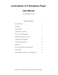
1
ION VERS 2014 1.4 Kom chno © Te TKLS – User Manual Table of Contents Introduction .........................................................................................................................4 Software Copyright Notice ...................................................................................................5 Safe Operation and Installation ...........................................................................................6 Product Overview ................................................................................................................7 Technical Specification........................................................................................................8 Scope of Supply ..................................................................................................................9 Components of sensor ......................................................................................................10 Sensor Installation ............................................................................................................. 12 Connection of the Sensor ..................................................................................................14 Power Supply Connection .................................................................................................16 RS-485 (TIA/EIA-485-A) Bus Connection .........................................................................17 Frequency Output Connection .......................................................................................... 18 Error Codes ....................................................................................................................... 19 Sensor Configuration.........................................................................................................20 Modbus Register Mapping ................................................................................................ 22 Appendix ........................................................................................................................... 24 3 TKLS – User Manual Introduction This User Manual applies to the TKLS fuel level sensor (hereafter – TKLS, sensor) produced by TechnoKom Ltd. It contains installation and connection procedures of the TKLS, as well as its function and control. This Manual is intended for specialists who are aware of the maintenance and installation principles typical for motor vehicles and are proficient in using the electronic and electrical equipment of various vehicles. To ensure the best performance of the TKLS, it should be installed and set up only by qualified specialists. The TKLS sensor can operate both as a part of a fuel monitoring system and as a part of a fleet management system. For proper operation of the TKLS sensor, the customer should be aware of the operating principles of these systems as a whole, as well as understanding the functions of its individual components Important! All information on functions, functional capabilities and other specifications related to TKLS fuel level sensors, as well as all information contained in this User Manual is based on current data (at time of writing) and is deemed to be valid as of the date of publication. TechnoKom reserves the right to modify the information or specifications without prior notice or commitment. 4 TKLS – User Manual Software Copyright Notice Products of TechnoKom referred to in this Manual may incorporate software stored in semiconductor memory or other media, copyrights to which belong to TechnoKom or third parties. Laws of the Russian Federation and other countries secure certain exclusive rights of TechnoKom and third parties to the software, which is subjected to copyright, for example, exclusive rights for distribution or reproduction. Therefore, any alteration, reverse engineering, distribution or reproduction of any software incorporated in TechnoKom products, is prohibited to the extent provided by law. Furthermore, purchase of TechnoKom products does not imply direct, indirect or other granting of any licenses related to copyrights, patents and patent applications of TechnoKom or any third party, except for an ordinary, nonexclusive free license for use, which is granted in virtue of law upon each sale of the product. When a TKLS is connected to an AutoGRAPH-GSM Series on-board vehicle tracking controller, the data is transferred to a data server using a communication protocol which is considered to be confidential information and intellectual property of TechnoKom. The communication protocol between the AutoGRAPH-GSM Series on-board vehicle tracking controllers and a communication data server shall be transferred by TechnoKom to integrators and software manufacturers only upon signing a Confidentiality Undertaking. Unauthorized distribution of the protocol used for communication between the AutoGRAPH-GSM Series on-board vehicle tracking controllers and communication data server is strictly prohibited. 5 TKLS – User Manual Safe Operation and Installation This section contains important information for effective and safe operation of TKLS fuel level sensors. Please read the information below before using the sensor. Sensors with damaged insulation of conductive parts, testing probe and body must not be used. Operational conditions of the TKLS such as electrical and environmental characteristics and condition of measured liquid should fit the requirements contained in this User Manual. Otherwise, the manufacturer will not be responsible for sensor safety and functional efficiency. All connections should be made when the sensor and external devices to be connected to the sensor are disconnected from the power supply. 6 TKLS – User Manual Product Overview The TKLS fuel level sensor is designed to measure fuel level in a vehicle fuel tank and transfer this information to external devices via one of the supported interfaces. The TKLS can be used as a replacement of the factory-fitted standard fuel level sensor or as an additional sensor for fuel level monitoring. The TKLS supports data transfer via RS-485 bus, in LLS and Modbus protocols, and via frequency output as pulses proportional to measured fuel level. In addition to fuel level, the sensor measures ambient temperature and sends the readings to an external device. Any device equipped with RS-485 which supports data exchange in LLS or Modbus protocols can operate as an external device (for example, a level indicator or an onboard vehicle tracking device). 7 TKLS – User Manual Technical Specification Description Output Interface Protocols for RS-485 Bluetooth (BLE) Built-in Accelerometer Self-diagnostic Error Report Remote Configuration via Bluetooth Remote Configuration via RS-485 Remote Firmware Update Logging Temperature Measuring Automatic Calibration Digital Input, numbers Frequency Output RS-485 (TIA/EIA-485-A), Frequency output LLS / ModBus Yes Yes Yes Yes Yes Yes Yes Yes Yes Yes 1 Output Frequency Range, Hz Output Type Maximum Load Current, mA Measuring Features 100…3000 Open collector 200 Operational liquids Level Measuring Accuracy, % Gasoline, Fuel oil ≤1 Moving-average or exponential 12 -40…+85 ±1 Averaging Methods Resolution, bit Temperature Measuring Range, °С Temperature Measuring Accuracy, °С Operational Conditions Operational Voltage, V Power Consumption at 12 VDC, mA Operational Temperature, °С Protection Class Probe Length, mm Mounting Average Life Time, years 8 Value +7…+60 < 30 -40…+85 IP69K 750 / 1500 / 2000 SAE 5-bolt pattern 10 TKLS – User Manual Scope of Supply № 1 2 3 3 4 Description “TKLS” Fuel Level Sensor with Plastic Cover Mounting Kit* Signal Cable in Corrugated Pipe Registration Certificate Warranty Certificate *The mounting kit includes following tools: Seal gasket Self-tapping screws with mounted washer and sealing, M5 size Rivet nut, knurled, M5 size Machine screw, M5 size Plastic seal Meter seal (for connector) End cap Fuse with holder Qty 1 pc. 1 set 7,5 m 1 pc. 1 pc. – 1 pc. – 5 pc. – 5 pc. – 5 pc. – 1 pc. – 1 pc. – 1 pc. – 1 pc. 9 TKLS – User Manual Components of sensor 1. 2. 3. 4. Product identification*. Mounting hole (x5). Interface Connector 1 (male). Sensor cover. 5. 6. 7. 8. Seal gasket. Measuring probe. End cap**. Sealing hole (x4). *Device designation contains trademark and contact details of the manufacturer, device description, serial number and release date of the device. **The sensor is supplied with a transport plug, which should be removed and replaced with the end cap before sensor installation. 10 TKLS – User Manual Interface Connectors Interface Connector 1 (male) View from side of pins No. Connector 2 (female) View from side of sockets Wire Colour Assignment 1 2 3 4 5 Red Orange Gray Black Brown +Vin RS-485 (A) Frequency output (ОК) -Vin RS-485 (B) 6 White Digital input (active low) Both connectors are keyed to prevent wrong orientation. 11 TKLS – User Manual Sensor Installation Before installation it is highly recommended to check the sensor for any mechanical damage. Sensor location The sensor location depends on the geometric form of the tank and should be chosen in such a way as to provide accurate readings regardless of fuel movement in the tank during vehicle motion. Normally, the sensor should be located at the center of the top of the tank. See figures below: If it is impossible to install the sensor as shown above, it should be located as close as possible to the recommended area. If, due to the geometric features of the tank, one fuel level sensor does not provide the required accuracy of readings, it is recommended that several sensors are installed into the tank. A set of two sensors is commonly used in this way. In this case, the fuel level in the tank amounts to the average readings of the two sensors. Preparation of the fuel tank All preparation work must be performed in accordance with the safety requirements specified for the tank: Before installation on a diesel tank, it must be filled with diesel. Before installation on a petrol tank, it must be completely emptied of petrol and filled with water. 12 TKLS – User Manual Before drilling, ensure that there aren’t any baffle plates inside in the tank in the proposed sensor installation area within a radius of 20 mm. This can be checked by drilling a small hole (about 3 mm) in the installation area. Drill a central hole 35…37 mm diameter using a bimetal boring bit. Drill five holes for SAE-5 bolts. Install the seal gasket on the sensor, then mount the sensor into the tank. Sensor Cutting The sensor length can be cut to match the specific fuel tank. To do this, you should follow these steps: Measure the tank depth by inserting a ruler in the tank through the central hole that has been prepared for installing the sensor. Measure the tank depth on the effective length of the sensor L. It is recommended that the sensor is shorter than the tank depth by 10-30 mm to prevent false reading due to impurities (including water) in the bottom of the tank. The effective length of the sensor should be adjusted depending on the amount of the impurities. When cutting the sensor, be sure that the cut is straight and perpendicular to the roll axis of the sensor. Remove the transport plug, which the sensor is supplied with, and install the supplied end cap in its place. Note. The effective length of the sensor must be at least 150 mm after cutting. 13 TKLS – User Manual Sensor Installation Install the seal gasket on the sensor with the wide side of the seal’s outer ring facing the tank (see figure below). When installing the seal, also be sure that the mounting holes of the sensor matches the mounting holes of the seal. Install the sensor into the tank and tighten five fastening screws supplied with the sensor. 14 TKLS – User Manual Connection of the Sensor This section covers connection procedures of the TKLS fuel level sensor: Power supply connection RS-485 bus connection Frequency output connection The sensor is supplied with a 7.5m signal cable in a corrugated pipe. The cable is equipped with a female connector (Connector 2) for connecting to the sensor (to Connector 1). Both connectors are keyed, which prevents incorrect orientation. When making connections, pay careful attention to the safety rules stipulated by the regulations for motor vehicle repair procedures. All connections should be properly isolated and securely connected. If the wire is too short, it can be spliced with a wire of at 2 least 0.5 mm cross section (20 AWG or thicker). The TKLS sensor can be connected to any external unit that supports ModBus or LLS protocols to transfer fuel level readings. The TKLS sensor is equipped with a frequency output that provides transfer of fuel level values in the form of pulses at a variable frequency. The sensor is also capable of measuring ambient temperature. 15 TKLS – User Manual Power Supply Connection When making the power connection, pay careful attention to the safety rules stipulated by the regulations for motor vehicle repair procedures. The sensor is supplied with a fuse intended to provide short circuit protection of the power supply. The fuse holder is installed on a wire ring, which should be cut before operation. The power supply input of the sensor is rated for a voltage of 7-60 V. To connect the power to the sensor you should follow these steps: Connect “+Vin” wire of the signal cable to “+Vin” line of vehicle power system and connect “-Vin” wire to “-Vin” line of the vehicle power system. Connect the fuse supplied with the sensor to the “+Vin” line. The fuse should be placed as close as possible to the point where the TKLS is connected to vehicle power system. Connect Connector 2 of the signal cable to the male Connector 1. 16 TKLS – User Manual RS-485 (TIA/EIA-485-A) Bus Connection The TKLS sensor is equipped with an RS-485 (TIA/EIA-485-A) bus, which allows the sensor to transfer collected data to an external unit equipped with RS-485. The TKLS supports the following commonly used data transmission protocols: LLS and ModBus. The data transfer protocol can be selected using the configuration program. The configuration program (“TKLSConf”) can be downloaded for free from the manufacturer’s official web site (www.tk-chel.ru). Note. For more information about sensor configuration using the TKLSConf Software see the “Sensor Configuration” section. General Diagram of Connection of External Devices to RS-485 Bus: The connection diagram of the TKLS to the “AutoGRAPH-GSM” on-board vehicle tracking controller is depicted in the figure below. This diagram is also true for other devices which are connected to the sensor via the RS-485 bus. Warning! Be careful not to cross the “A” and “B” wires, otherwise the sensor may operate incorrectly. Warning! All connections should be performed when the sensor and all external devices to be connected to the RS-485 bus are disconnected from the power supply. 17 TKLS – User Manual Frequency Output Connection TKLS sensor is equipped with one frequency output, which is open-collector. The frequency of the output signal is proportional to the fuel level in the tank. The output frequency range varies from 100Hz to 3000Hz. Maximum load current should not exceed 200 mA. The frequency output is intended to be connected to the digital input of the “AutoGRAPHGSM” on-board vehicle tracking device, which can acquire the reading in frequency form. Before connecting to the TKLS, the input of the “AutoGRAPH-GSM” must be switched to Frequency Mode. Internal Diagram of Frequency Output: General Connection Diagram for Frequency Output: Important! All connections should be performed when the sensor and all external devices to be connected to the frequency output are disconnected from the power supply. 18 TKLS – User Manual Error Codes The TKLS sensor has an embedded self-diagnostic procedure that provides detection of errors during sensor operation. When connected to the “AutoGRAPH-GSM” controller via RS-485 bus the TKLS sends error codes (if any) to the controller. The code will be recorded in the controller as a temperature record. Error Code Description Error Code -127 -126 -125 -124 Error / failure description short circuit capacitance probe break frequency out of calibration range built-in accelerometer fault Important! The TKLS sensor transfers the error code via RS-485 only when it is connected to the “AutoGRAPH-GSM” or “AutoGRAPH-WiFi” onboard vehicle tracking controllers. When connecting to other external device, the error code won’t be transferred. Diagnostic operation can be performed using the “TKLSConf” configuration program. If an error has occurred, this will be shown in the program window. 19 TKLS – User Manual Sensor Configuration The TKLS can be set up in the following ways: Using the «TKLSConf» Configuration Software; remotely via Bluetooth; remotely via RS-485; To set up the sensor using the “TKLSConf” program it is necessary to connect the device to a PC or a laptop. For correct operation, the sensor drivers should be installed before connection. If the device drivers have not been installed, follow the steps in the “Installing the Drivers” section. To connect the sensor to a PC, use the special adaptor and USB data cable supplied with the sensor (see fig.1). Fig.1 – Connection to a PC. To connect the sensor to a PC follow these steps: turn off the sensor power supply; connect the 4-pin connector of the USB cable to the 4-pin connector of the adaptor (see fig.2, step 1); connect the USB cable to the PC (fig.2, step 2); connect the free end of the adaptor (Molex connector) to Connector 1 of the sensor (fig.2, step 3); turn on the sensor power supply; if the sensor drivers were previously installed, the PC will automatically detect the connected device. 20 TKLS – User Manual Note. For more information on the “TKLSConf” Software see “TKLS Configuration Software” help file. The “TKLSConf” Software provides configuration of the sensor via the RS-485 bus. The customer can specify the settings in the “TKLSConf” program and send them to the data server. These settings will be transferred to the “AutoGRAPH” onboard controller which is connected to the sensor and after that will be transferred to the sensor via the RS-485 bus. The sensor supports remote configuration via Bluetooth using a mobile device. To do this, the Bluetooth option must be enabled in the sensor’s settings and an access password must be known by the customer. 21 TKLS – User Manual Modbus Register Mapping The TKLS is capable of communication via the RS-485 serial bus in the Modbus/RTU protocol. The TKLS supports the Modbus function 03 – Read Holding Registers. Address (HEX) 22 Description 0x00 TKLS address 0x01 RS-485 baud rate (high bit) 0x02 RS-485 baud rate (low bit) 0x03 Full calibration (high bit) 0x04 Full calibration (low bit) 0x05 Zero calibration (high bit) 0x06 Zero calibration ( low bit) 0x07 Averaging time / weighting coefficient (%) 0x08 Temperature 0x09 Raw fuel level data (high bit) 0x0A Raw fuel level data (low bit) 0x0B Fuel level 0x0C Serial number (high bit) 0x0D Serial number (low bit) 0x0E Averaging method 0x0F Output frequency when tank is full 0x10 Output frequency when tank is empty 0x11 Raw fuel level data before temperature-compensation (high bit) 0x12 Raw fuel level data before temperature-compensation (low bit) 0x13 Averaged raw fuel level data (high bit) 0x14 Averaged raw fuel level data (low bit) 0x15 Error code (high bit) 0x16 Error code (low bit) 0x17 Number of input pulses (high bit) 0x18 Number of input pulses (low bit) 0x19 Roll angle 0x1A Pitch angle TKLS – User Manual Note. Reading Modbus Holding Registers is supported by the firmware of revision TKLS-1.27 23 TKLS – User Manual Appendix APPENDIX 1: SAE-5 MOUNTING. APPENDIX 2: BUILD-IN ACCELEROMETER AXES ORIENTATION 24 USER MANUAL V 1.4.0 TechnoKom Ltd. Copyright © Chelaybinsk, 2014. All Rights Reserved.