1
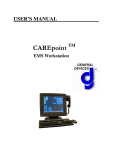
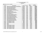
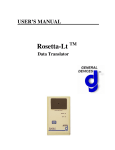
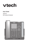
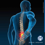
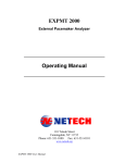
USER’S MANUAL Rosetta-Rx TM Data Receiver IMPORTANT Federal (USA) law restricts this device to sale by or on the order of a physician. This instrument is to be used by authorized personnel only. Responsibility for Information It is the customer’s responsibility to ensure that the appropriate personnel within their organization have access to this manual, including the safety information provided in Section 1. General Devices 1000 River St. Ridgefield, NJ 07657 Phone: (201) 313-7075 Fax: (201) 313-5671 Internet: www.general-devices.com Rosetta, Rosetta-Lt, Rosetta-Rx, CAREpoint, GEMS, and GEMSCOM are trademarks of General Devices. LIFEPAK is a registered trademark of Medtronic Physio-Control Corporation. M Series is a trademark of Zoll Medical Corp. Specifications subject to change without notice. ©October 2005 General Devices. DOC 1858002 Rev C Rosetta-Rx User’s Manual ii Table of Contents Section 1 General Information 1.1 Safety Information .......................................................................................... 1-1 1.2 Intended Use.................................................................................................... 1-2 1.3 Glossary of Terms ........................................................................................... 1-2 1.4 Text Conventions ............................................................................................ 1-2 Section 2 Description 2.1 Physical Description........................................................................................ 2-1 2.2 Controls, Indicators and Connectors ............................................................... 2-1 Section 3 Connections 3.1 DC Power ........................................................................................................ 3-1 3.2 Input (Communications) ................................................................................. 3-1 3.3 Printer.............................................................................................................. 3-1 Section 4 Operation 4.1 Operating Instructions..................................................................................... 4-1 4.2 Operation over Noisy or Poor Communications............................................. 4-2 Section 5 Maintenance, Test and Service 5.1 Maintenance .................................................................................................... 5-1 5.2 Testing............................................................................................................. 5-1 5.3 Troubleshooting .............................................................................................. 5-2 5.4 Service and Repair .......................................................................................... 5-3 5.5 Warranty Policy .............................................................................................. 5-4 Section 6 Configuration Programming 6.1 Program Mode................................................................................................. 6-1 6.2 Configuration Settings .................................................................................... 6-1 Appendix A Specifications A.1 Performance Specifications............................................................................ A-1 Appendix B Additional Communications Equipment Information B.1 Compatible Communications Equipment....................................................... B-1 B.2 Connecting to Telephone Lines ..................................................................... B-1 B.3 Connecting to 2-Way Radio Equipment ........................................................ B-2 Appendix C Additional Printer Information C.1 Compatible Printers ........................................................................................ C-1 Appendix D Sample Printouts D.1 Sample Printouts ............................................................................................ D-1 Appendix E Options, and Accessories E.1 Options............................................................................................................ E-1 E.2 Accessories ..................................................................................................... E-1 Rosetta-Rx User’s Manual iii Section 1 General Information This manual provides descriptions, connection information, operating instructions as well as maintenance and service information for the General Devices' Rosetta-Rx Data Translator. 1.1 Safety Information DO NOT OPERATE THIS EQUIPMENT WITHOUT FIRST REVIEWING THIS SAFETY INFORMATION! The following terms are used in this manual: CAUTION: Hazards or unsafe practices that may result in minor personal injury, product or property damage. WARNING: Hazards or unsafe practices that may result in serious personal injury or death. CAUTIONS! • Before operation, read entire manual. • This device is to be used by authorized personnel only. • This device may require periodic maintenance to assure proper operation. Refer to Section 5 for maintenance information. • Should the device appear to perform improperly, refer to Section 5 for test and servicing information. • Do not connect or operate this device in any manner other than that specified within this manual or any of the addendums included with this manual. • Before operation, check to insure that information is reliably transmitted over the communications system you are using. • Depending upon transmission equipment and conditions, information received at hospital may be noisy or incomplete. In such cases, the printout indicates where this has occurred. Refer to Section 4 for additional information. WARNINGS! • Possible explosion hazard if used in the presence of flammable anesthetics or gases. • Do not immerse in water or other fluids. Do not allow water or fluids to enter case. Rosetta-Rx User’s Manual 1-1 GENERAL DEVICES AND IT’S AGENTS ARE NOT RESPONSIBLE FOR ANY DAMAGE OR CONSEQUENCES RESULTING FROM IMPROPER OR UNAUTHORIZED USE OF THIS PRODUCT. 1.2 Intended Use The intended use for the Rosetta-Rx is to provide a convenient, practical means to present ECG and/or other physiologic information acquired in an EMS pre-hospital setting and transmitted via a Rosetta device using standard communication means, such as 2-way radio, landline or wireless telephone. 1.3 Glossary of Terms and Abbreviations • FM: Frequency Modulation, a commonly used method of formatting information for transmission by radio or telephone. • FSK: Frequency Shift Keying, a commonly used method of formatting data at relatively low baud rates for transmission by radio or telephone. • DTMF: Dual Tone/Multi-Frequency is the technical name for “touch-tone” dialing and is a commonly used method of signaling for transmission by radio or telephone. • LP-12: LIFEPAK 12 monitor-defibrillator manufactured by Medtronic PhysioControl corporation of Redmond Washington, USA. • M Series: M Series monitor-defibrillator manufactured by Zoll Medical Corporation of Clemsford MA, USA. • RTL: Radio Tie Line, a dedicated or leased wire-line used to pass audio signals to or from 2-way radio communications equipment. • STL: Standard Telephone Line, a standard dial-up telephone line used in a private public switched telephone network (PSTN). 1.4 Text Conventions Throughout this manual, special text characters are used to indicate controls, labels and prompts. • Control, Indicator and Connector Labels: Italic letters such as Print Rosetta-Rx User’s Manual 1-2 Section 2 Product Description This section describes the general features, specifications, controls, indicators, and connectors for the Rosetta-Rx. Drawings of the Rosetta-Rx are provided in Figures 2-1 and 2-2. 2.1 Description The General Devices Rosetta family of products provides a means for communicating physiologic information (waveforms and data) over standard communications means, such as 2-way radio, landline or wireless (cellular) telephone, from a pre-hospital location to a hospital. The Rosetta-Rx is a data receiving device that connects to the available communications means and receives single or 12 lead ECG and summary data that was acquired by a (compatible) monitor/defibrillator and “translated” by a Rosetta-Lt. The received data is printed via a connected standard laser printer. It is intended to provide distant health care professionals convenient access to such information to assist in providing medical guidance as well as documentation for medical/legal purposes. The Rosetta-Rx is a compact stand-alone desktop unit powered by a 9 Volt DC wall adapter module. 2.2 Controls, Indicators and Connectors Controls (Stand-Alone) • Print button........................................ Starts and stops printing of received data • Filter button....................................... Turns the noise filter on/off Indicators (Stand-Alone) • Power LED........................................ Green, lit indicates power is on • Data LED .......................................... Green, blinking indicates unit is inputting (receiving) data, lit solid indicates unit has 12L ECG/data stored in memory • Filter LED ......................................... Green, lit indicates noise filter is on • Error LED ......................................... Red, blinking with Printer LED indicates printer error, lit solid or blinking alone indicates a failure Connectors • DC PWR ............................................ DC Power jack for connection to a 9 VDC wall adapter module (Stand-Alone only) Rosetta-Rx User’s Manual 2-1 • Input................................................... Connection to radio/phone for inputting received ECG/Data (RJ-11 jack) (StandAlone only) • Printer ............................................... Connection to compatible laser printer for outputting formatted ECG/Data • RS-232 ............................................... Serial port (DB-9) connection to compatible equipment Rosetta-Rx User’s Manual 2-2 R os et ta D GE EV N IC ER ES AL R x Po D 5.450 w er at a Pr in Fi t lt e r Er ro r 1.800 7.500 Figure 2-1 Rosetta-Rx (Stand-Alone) Dimensions L A ER ES N E IC G EV D R ta et os R x er a w at D Po t in Pr r lte Fi r ro Er FRONT PANEL INPUT PRINTER DC PWR REAR PANEL Figure 2-2 Rosetta-Rx Controls, Indicators and Connectors (Stand-Alone) Rosetta-Rx User’s Manual 2-3 Section 3 Connections This section contains information for connection of the Rosetta-Rx to power, input (communications) equipment and printer. 3.1 Power Power for the Rosetta-Rx is provided via connection to an external DC power source. • Power connection to the Rosetta-Rx is provided via an external 9 Volt DC wall adapter module connected to the DC PWR connector. 3.2 Input A connection to communications equipment (radio/phone) is required for inputting ECG/Data signals to the Rosetta-Rx. • Input connection for the Rosetta-Rx this is made via the Input connector using a standard RJ-11 telephone type cord. Refer to Appendix B for additional information on connections to communications equipment. o Connection to standard telephone equipment (STL) is made as if the Rosetta-Rx is a parallel extension on the phone line. This can be accomplished using a “splitter” or a second jack. o Connection to 2-way radio equipment (RTL) is made with the RosettaRx as a parallel extension “bridging” the Receive (RX) audio pair. This can be accomplished using a “splitter” or a second jack. 3.3 Printer A Printer port connection is provided by the Rosetta-Rx for outputting the formatted ECG and summary data to a compatible laser printer. Refer to Appendix C for additional printer information. • Printer connection for the Rosetta-Rx is provided via a DB-25F parallel printer port for use with a standard Centronics type printer cable. Rosetta-Rx User’s Manual 3-1 Section 4 Operation This section contains operating information for the Rosetta-Rx. Refer to Sections 2 and 3 for additional description and connection information. 4.1 Operating Instructions The Rosetta-Rx unit is extremely easy to use and has only a few controls and indicators. Operation is automatic for receiving and printing of ECG and summary data as no user action is required. Power On/Off There is no On/Off button, the Rosetta-Rx is always on when power is applied and is indicated by the Power LED. • Power LED lights Green when power is on. Receiving and Printing Rosetta-Rx automatically receives and prints single lead ECG “strip” or 12 lead ECG and summary data sent via a Rosetta device. Operation occurs in two phases, reception and printing as follows: • The Reception phase occurs after detection of a signal sent via a Rosetta transmitting device. o Data LED blinks while receiving ECG/data o Data LED lights solid after receiving and storing the ECG/data in memory • The Printing phase occurs shortly after the conclusion of the receiving phase. o Print LED blinks while transferring the data to the connected laser printer ¾ If a printer error (out of paper, etc.) is detected; o Error LED blinks with the Print LED o The laser printer then prints out the received ECG/data (print time varies with printer type). Manual Printing Operation The user can cancel a printout or reprint an ECG/Data stored in memory (Data LED lit) using the Print button. • Pressing the Print button while data is being transferred to the printer (Print LED blinking) will cancel the printout. Rosetta-Rx User’s Manual 4-1 • Pressing the Print button while ECG/Data is stored in memory (Print LED lit solid) will initiate a printout. Noise Filter Operation The Filter button controls a noise filter (low-pass filter) that can remove or reduce unwanted high frequency noise from the ECG signal. ¾ Note: Whenever the noise filter is ON, the ECG no longer has diagnostic frequency response and there may be some attenuation of the R-wave. • The Filter button is functional only when data is not being transferred to the printer, therefore the desired filter state (On/Off) must be selected prior to printing. • Filter LED is lit when the noise filter is enabled or On • Printouts generated with the noise filter on are annotated with “Filter On” and the (non-diagnostic) filtered bandwidth is indicated. Clearing ECG/Data From Memory ECG/Data stored in memory is automatically cleared (erased): • After 30 minutes • At power off 4.2 Operation over Noisy or Poor Communications Rosetta utilizes a robust scheme enabling it to operate in a wide variety of communications environments, however, depending on the type of communication medium used (radio, landline, analog or digital cellular) and conditions, not all the transmitted information may be received at the hospital receiving equipment at all times. Missing information may include summary information (interpretation, device identification) and pacemaker markers. At times, the ECG may also have unusual amounts of baseline noise. Although any missing information is indicated on the printout and should be obvious to the physician, it would be prudent to verify that the physician has taken note of this by asking the physician if the printout contains any missing information or baseline noise. If so, the information may be provided verbally or resent when conditions improve. Refer to Appendix D for sample printouts. Rosetta-Rx User’s Manual 4-2 Section 5 Maintenance, Test and Service This section describes the maintenance, test and service aspects of the Rosetta-Rx. 5.1 Maintenance The Rosetta-Rx requires no special maintenance other than periodic maintenance and general cleaning. Periodic Maintenance (PM) Periodic maintenance is important to help prevent and identify possible performance and operational discrepancies. PM Testing procedure to be provided here, contact factory PM instructions. Cleaning (Stand-Alone Only) • The Stand Alone enclosure may be cleaned with a mild cleansing agent such as Windex. • DO NOT use any abrasive-cleaning agents, such as scouring powder. • DO NOT apply excessive liquid near openings where seepage may damage internal components. 5.2 Testing Under normal conditions, the Rosetta-Rx requires no special testing other than functional testing. Functional Testing Functional testing is intended to help identify possible performance and operational discrepancies. Should testing reveal a possible discrepancy, perform the Self Test and troubleshooting described in Section 5.3. If the discrepancy cannot be corrected, immediately remove the device from service and refer to Section 5.4 for information on how to obtain authorized service or repair. • Transmit a single lead ECG (from a known good monitor / ECG simulator) from a known good Rosetta-Lt over a known good communications means. Compare the monitor’s printout with the received printout and verify the waveforms match. • Transmit a 12-lead ECG (from a known good monitor / ECG simulator) from a known good Rosetta-Lt over a known good communications means. Compare the monitor’s printout with the received printout and verify the waveforms and data match. Rosetta-Rx User’s Manual 5-1 Self Test Self Test is intended to help identify possible performance and operational discrepancies. Should Self Test reveal a possible discrepancy, refer to the troubleshooting described in Section 5.3. If the discrepancy cannot be corrected, immediately remove the device from service and refer to Section 5.4 for information on how to obtain authorized service or repair. • With the Rosetta-Rx powered on and a printer connected: o Press the Print button, o Press the Filter button, o Press the Print button again, o Press the Filter button again, o Press the Print button, again o Self Test will begin. • In Self Test mode: o The Data LED will blink for several seconds as test data is generated, then o the Print LED will light as the test data is sent to the printer, then o the printer will print the self test data. • Examine the self test printout & verify: o EEPROMTest is “N/A” o RAM Test is “PASSED” o DUARTTest is “PASSED” o FirmwareVer is shown (example 0.50), o The Cal Pulse (at start of waveform) is 0.8 boxes wide x 2.0 boxes high, o The saw-tooth waveform is shown as 2 rows of 10 complexes each, and each complex is 5.0 boxes wide by 4.6 boxes high. 5.3 Troubleshooting Should the Rosetta-Rx appear to operate improperly: • Reboot the unit by unplugging the DC PWR plug, waiting 10 seconds and reconnecting the power plug. • Perform Self Test (see Section 5.2 above). • Perform Functional test (see Section 5.2 above). If the problem is not resolved: Rosetta-Rx User’s Manual 5-2 • Verify that the Power LED is lit – if not, check power cord – both ends. • Verify that the Error LED is NOT lit – if it remains lit or blinking obtain service. • Verify the radio or phone line to the Rosetta-Rx is connected and receive audio is present (may need assistance from telecomm or radio service). • Verify the printer cable is connected (both ends). • Verify the printer is powered on, has paper and has no errors. • Attempt to perform the Self Test. If the troubleshooting does not resolve the problem, or self test indicates errors, immediately remove the device from service and refer to Section 5.4 for information on how to obtain authorized service or repair. 5.4 Service and Repair The Rosetta-Rx contains no serviceable parts. Interconnect cables are prone to damage and may be repaired by any qualified electronic technician or replaced. If, after following the General Troubleshooting guide, the problem can not be corrected or it is determined that the Rosetta-Rx requires service, contact General Devices and have the following information ready: 9 Model number 9 Serial number 9 Description of problem, be specific & include all symptoms and conditions 9 Results of following the Self Test and Troubleshooting 9 Type of cell phone/radio used and type of connection 9 Sample strips from the monitor/defibrillator and hospital receiving unit Support/Service Hours: Factory technical telephone support is provided during normal business hours Monday through Friday, from 10:00 AM to 5:00 PM EST. Twenty-Four (24) hour telephone service coverage may be provided for warranty or extended warranty service at an additional cost where such services are available. Direct factory services are NOT available beyond regular business hours. Contact Information: General Devices 1000 River St. Ridgefield, NJ 07657 Attn: Service Department Phone: (201) 313-7075 Rosetta-Rx User’s Manual 5-3 Fax: (201) 313-5671 e-mail: [email protected] Internet: www.general-devices.com Returning Materials To Factory A Returned Materials Authorization number (RMA) must be obtained from the service department and marked on the outside of any package to be sent to the factory for service. Packages received without an RMA number may be rejected. 5.5 Warranty Policy Items Covered by Warranty The General Devices' Rosetta-Rx is warranted against all defects in parts and workmanship for one year from date of delivery. General Devices will repair or replace any unit which it deems defective, provided it is within the warranty period and proper use and maintenance procedures have been followed as prescribed in this manual. The warranty provides replacement parts and labor, F.O.B. Ridgefield, New Jersey. Items Not Covered by Warranty General Devices or its agents are not responsible for any problems related to nonGeneral Devices supplied equipment as well as connections to unauthorized equipment. Items having failed due to mishandling, improper usage, improper power source, lightning strikes or other natural disaster, fire, water damage, etc., are not covered by this warranty. Semi-annual and annual inspections are not provided for under warranty. Other Warranty Terms and Conditions All warranty work is performed at the factory. Should service personnel be requested on-site for a problem, the customer will be billed at the current rate for such services. No other party is authorized to make any other warranty, or to assume any liability for General Devices’ products. No other warranty, either expressed or implied, will be recognized. Non-Warranty Service Non-Warranty service is provided by General Devices at its current hourly rate (contact factory for current service rates). Work performed on factory premises is billed for actual bench time and materials, plus shipping and handling. Work performed on customer premises is billed for time (portal-to-portal), travel expenses and materials. Rosetta-Rx User’s Manual 5-4 Section 6 Configuration Programming This section describes how to set the programmable configuration settings. The correct program settings are required to match the communications hook up for proper operation. Refer to Appendix B for more information on communications connections. 6.1 Program Mode To Enter Program Mode: • Disconnect the DC PWR plug • Wait 5 seconds • Re-plug in the DC PWR plug • Immediately Press AND continue to hold both o Print button and o Filter button • Data LED will light green (continue holding buttons) • When Data LED goes off – release both buttons Program Mode Operation • Print button is the “Program” select button • Print LED blinks out the “Program” number (number of blinks) • Filter button is the “Setting” select button • Filter LED blinks out the “Setting” number (number of blinks) Example: LED’s - Print = 1 Blink, Filter = 0 Blinks Means - Program 1, set for Radio 6.2 Configuration Settings Program 1: Line Type .................................. Print LED blinks 1 time The line type setting specifies the type of connection as radio or telephone. Setting (Filter LED blinks Setting #) 0 Radio 1 Telephone Rosetta-Rx User’s Manual 6-1 Program 2: Auto Answer ............................. Print LED blinks 2 times The auto-answer setting specifies number of rings that must be detected before the Rosetta-Rx goes off-hook (answers). Program 2 not applicable for radio (Program 1=0) Setting 0 1 2 3 4 5 (Filter LED blinks setting #) No Auto Answer Answer after 1 ring (default) Answer after 2 rings Answer after 3 rings Answer after 4 rings Answer after 5 rings Program 3: Default Filter ............................ Print LED blinks 3 times The default filter setting sets the Filter function as on or off at power up. Setting (Filter LED blinks setting #) 0 Filter Off 1 Filter On (recommended) Program 4: Single Lead FM Detect ........... Print LED blinks 4 times The single lead FM detect feature allows single lead telemetry to be received (once detected) even if the start DTMF’s from a Rosetta-LT are not received or if it is from non-Rosetta-LT equipment. Setting (Filter LED blinks setting #) 0 No FM Detect 1 Detect - Narrow Band; assumes standard 50Hz/mV (factory default) 2 Detect – Wide Band; assumes 250Hz/mV Program 5: Auto Print ................................. Print LED blinks 5 times The auto-print setting whether single or 12 leads get printed automatically. Setting 0 1 2 3 (Filter LED blinks setting #) No auto-print Auto-print single lead only Auto-print 12 lead only Auto-print single and 12 lead (factory default) Rosetta-Rx User’s Manual 6-2 Appendix A Specifications This appendix provides additional information on specifications and performance. A.1 Performance Specifications 1 Demodulator Format ................................................ FM/FSK Center Frequency ................................ 1400 +/- 5 Hz Deviation ............................................. Selectable, 50, 250 Hz/V Frequency Response ........................... DC to 150 Hz (+1, -3 dB) Range................................................... +/-2.5V FSK ..................................................... 1.2/1.6 KHz ECG Waveform............................................ FM 12 Lead Summary Data....................... FSK Serial Data 12 Lead Translation time .................... 15 Sec. (nominal) Controls & Indicators Keys & Switches ................................. Print, Filter Indicators............................................. Power, Data, Print, Filter, Error Connections Input (stand-alone) .............................. RJ-11, 10K Ohm balanced, AC Coupled Printer.................................................. DB-25F, Centronics parallel port RS-232................................................. DB-9M, EIA-232 Serial Port Power ..................................................... 9 VDC, <500 mA wall adapter (stand-alone) Mechanical Size ...................................................... 7.6” x 5.5” x 1.90” (stand-alone) Weight ................................................. 1.2 Lbs. Notes 1) Specifications subject to change without notice. Rosetta-Rx User’s Manual A-1 Appendix B Additional Communications Equipment Information This appendix provides additional information regarding communications equipment to be used with the Rosetta-Rx Stand-Alone version. B.1 Compatible Communications Equipment 1 • • Telephone Lines .................... Standard analog “dial-up” (POTS) telephone lines 2-Way Radio Equipment ....... UHF, VHF, 800, Conventional or Trunked - analog (600 Ohm RX audio pairs/lines). Notes 1) Radio channels must be “analog” voice channels / talk groups. 2) The Rosetta-Rx operates within the voice band (300-3000Hz) of standard radio and telephone communications systems used by EMS and Public Safety services and will normally provide reliable transmission. The user should be aware that older or nonstandard or poorly maintained systems/equipment may not provide reliable operation. The performance Rosetta transmissions over digital cellular telephones varies widely and is dependant upon compression scheme, Vocoder type and other factors common to cellular telephone such as distance to cell, hand-off’s, etc. Be sure to test all equipment prior to use to assess performance. B.2 Connecting to Telephone Lines For installations where the Rosetta transmission will be received over a standard analog “dial-up” telephone line, the Rosetta-Rx is simply connected as a parallel “extension” to the phone that will be used for voice communications with the Physician. This connection is made via a standard RJ-11 (telephone type) modular cord that plugs into a phone jack “splitter” or to a 2nd (parallel) jack as shown in Figure B-1. Note: Rosetta only works with analog telephone lines. If your telephone system is digital, you will need to have an analog line installed. Rosetta-Rx User’s Manual B-1 Figure B-1: Example Telephone Connection for Rosetta-Rx Stand-Alone B.3 Connecting to 2-Way Radio Equipment For installations where the Rosetta transmission will be received over a 2-way radio system, the Rosetta-Rx is simply connected in parallel to or “bridging” the Receive (RX) pair or line that goes to the radio control console or desk-set. This connection is made via a standard RJ-11 (telephone type) modular jack. If your radio console/deskset is hard wired without a RJ-11 jack, you will need to install one for connection to the Rosetta-Rx. The Rosetta-Rx’s RJ-11 input jack uses the Red-Green pair (inner or 1st line/pair) for the receive audio. If your radio console is wired with the receive audio on the BlackYellow (2nd line or outer pair), common in 4-wire systems, you will need to either add an additional jack with RX on the Red-Green pair or use a splitter that breaks out the 2nd line. If your radio console/desk-set connects to multiple receive pairs (e.g. systems with multiple base stations), the Rosetta-Rx should instead be connected to a point that provides “selected” audio at a constant level (i.e. NOT speaker audio). The Rosetta-Rx features an AC coupled, high impedance input and will not load or affect receive audio quality or level. Some common hook-up diagrams are provided in Figure B-2. Consult with your radio service provider before connecting to or modifying your radio equipment. Contact General Devices’ technical support for more information. Rosetta-Rx User’s Manual B-2 Figure B-2: Example Radio Connections for Rosetta-Rx Stand-Alone Rosetta-Rx User’s Manual B-3 Appendix C Additional Printer Information This appendix provides additional information regarding printer equipment to be used with the Rosetta-Rx. C.1 Compatible Printers 1 • • HP Laser Jet........................... 4L, 5L, 6L, 4000 series Other Laser Jet....................... All HP-GL and PCL-5 compatible Notes: 1. Printer must have an available standard “Parallel” type connect. RosettaRx cannot connect via USB or Ethernet. 2. Be sure to test all equipment prior to use to assess performance. Rosetta-Rx User’s Manual C-1 Appendix D Sample Printouts This appendix provides sample Rosetta printouts to illustrate transmissions of single and 12-lead ECGs. D.1 Sample Printouts • Figure D-1: Single Lead ECG • Figure D-2: 12-Lead ECG Rosetta-Rx User’s Manual D-1 Figure D-1: Single Lead ECG Rosetta-Rx User’s Manual D-2 Figure D-2: 12-Lead ECG Rosetta-Rx User’s Manual D-3 Appendix E Options and Accessories This section describes options and accessories for the Rosetta-Rx. E.1 Options No options are currently available E.2 Accessories No accessories are currently available Rosetta-Rx User’s Manual E-1