1
Operation
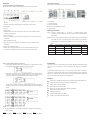
Back Panel Description
Front Panel Controls and LCD Indicators
Shown below are the components on the back of Inverter/Charger.
Shown below are the controls and indicator lights on the front of Inverter/Charger.
1. Input Breaker
2. AC Input Connector
1. Power On: Please make sure the battery connection before you turn on the
3. Output Receptacle(s)
Inverter/Charger
4. DC Input Connector (Battery Terminal)
2. UPS Off
5. Output Breaker
3. Charger Only
Battery Connection
4. UPS Test Switch: When UPS is working under AC mode, it also activates the UPS’s
Step 1. Connect to 12V(24V) battery. “+” is positive, “-“ is negative. Reverse polarity
self-test by press the bottom.
connection will blow internal fuse and may damage inverter permanently.(See
5. Line-On: AC Normal
Specification)
6. O-Temp. : If the UPS is over temperature, the light will turn on and the alarm will sound
Step 2. DC to AC inverters require high amperage / low voltage DC power to low amperage /
continuously.
high voltage AC power. To operate properly connect inverter DC input terminals
7. Back-Up: Battery in back-up
direct to battery with heaviest wire available (no more than 100cm), see chart
8. Over Load: If the UPS is overloaded, the light will turn on and the alarm will sound
below:
continuously
Model
9. UPS Cut-Off: Overload or Cut-off
10. Battery Level: A bar graph showing how much of the UPS battery is being used.
11. Load Level: A bar graph showing how much of the UPS power is being used.
DC Input Voltage Max. Watts Out Approx. Amps Req’d Wire Gauge
IN1000
12V
600W
85A
8AWG*2
IN1500
12V
900W
125A
4AWG*2
IN2000
24V
1200W
85A
8AWG*2
IN3200
24V
2000W
140A
2AWG*2
Introduction
Step 3. Connect battery cables to your batteries
¾ Single battery connection: When using a single battery, its voltage must be equal to
The Device is a DC-to-AC inverter with auto line-to-battery transfer and integrated charging
system, serving as an extended run UPS, a standalone power source or an automotive
the voltage of Inverter/Charger Nominal Input Voltage (see specs)
inverter.
Inverter/Charger supplies power from AC power and DC source. When AC cable is
¾ Series battery connection: When using multiple batteries in series, all batteries must
be equal in voltage and amp hour capacity, and the sum of their voltages must be
equal to the voltage of Inverter/Charger Nominal Input Voltage (see specs)
connected to a wall socket, utility power goes to connected equipment(s) and/or charges the
battery set via charging system. In UPS mode, Inverter/Charger automatically convert battery
energy into AC power for backing up the connected devices.
Features:
9
30Amp built in powerful smart charger for long backup time and extended battery life.
9
High efficiency and low idle current to keep low operating costs.
¾ Parallel battery connection: When using multiple batteries in parallel, each battery’s
9
Quiet operation, heavy duty reliability.
voltage must be equal to the voltage of Inverter/Charger Nominal Input Voltage (see
9
Ecologically smart and user friendly.
9
Back-up, on-line, battery status, power status by LCD display.
9
Short circuit and overload protection.
9
Cold start (DC power on).
9
Advanced battery management (ABM).
9
Charging current can be adjusted by selector.
specs)
Step 4.
Ɉġ Charger Current Switch: You can adjust the position of Dip Switch to adjust charging
currency of battery.
30Amp(40Amp)
20Amp(30Amp)
10Amp(20Amp)
5Amp(10AMP)