1
Fibre Channel - Storage Systems
8FA
SurfRAID TRITON 8FA User’s Manual
Support - 800-550-3005
Chapter 1
Introduction
The SurfRAID TRITON 8FA is a Fibre channel-to-Serial ATA RAID (Redundant
Arrays of Independent Disks) disk array subsystem. It consists of a RAID
disk array controller and eight (8) disk trays.
The SurfRAID TRITON 8FA is “Host Independent” supporting RAID levels 0,
1, 3, 5, 6, 0+1 and JBOD. Regardless of the RAID level the subsystem is
configured for, each RAID array consists of a set of disks which to the user
appears to be a single large disk capacity.
One unique feature of these RAID levels is that data is spread across separate disks as a result of the redundant manner in which data is stored in a
RAID array. If a disk in the RAID array fails, the SurfRAID TRITON 8FA continues to function without any risk of data loss. This is because redundant
information is stored separately from the data. This redundant information will
then be used to reconstruct any data that was stored on a failed disk. In
other words, the SurfRAID TRITON 8FA can tolerate the failure of a drive
without losing data while operating independently of each other.
The SurfRAID TRITON 8FA is also equipped with an environment controller
which is capable of accurately monitoring the internal environment such as
its power supplies, fans, temperatures and voltages. Its modular design allows hot-swapping of hard drives without interrupting the SurfRAID TRITON
8FA’s operation.
Introduction
1-1
1.1 Key Features
SurfRAID TRITON 8FA Features:
v Features an Intel 80321 64 bit RISC I/O processor
v
v
v
v
v
v
v
v
v
v
v
128MB cache memory, expandable up to 1024MB
2Gb Fibre channel, dual loop optical SFP LC (short wave) host port
Smart-function LCD panel
Supports up to eight (8) 1" hot-swappable Serial ATA hard drives
Redundant load sharing hot-swappable power supplies
High quality advanced cooling fans
Local audible event notification alarm
Supports password protection and UPS connection
Built-in R-Link LAN port interface for remote management & event
notification
Dual host channels support clustering technology
Real time drive activity and status indicators
RAID Function Features:
v
v
v
v
Supports RAID levels 0, 1, 0+1, 3, 5, 6 and JBOD
v
v
v
v
v
v
Transparent data protection for all popular operating systems
1-2
Supports hot spare and automatic hot rebuild
Allows online capacity expansion within the enclosure
Tagged command queuing for 255 commands, allows for overlapping
data streams
Bad block auto-remapping
Supports multiple array enclosures per host connection
Multiple RAID selection
Array roaming
Online RAID level migration
Introduction
1.2 RAID Concepts
RAID Fundamentals
The basic idea of RAID (Redundant Array of Independent Disks) is to combine
multiple inexpensive disk drives into an array of disk drives to obtain performance,
capacity and reliability that exceeds that of a single large drive. The array of
drives appears to the host computer as a single logical drive.
Six types of array architectures, RAID 1 through RAID 6, were originally defined,
each provides disk fault-tolerance with different compromises in features and
performance. In addition to these five redundant array architectures, it has become
popular to refer to a non-redundant array of disk drives as a RAID 0 array.
Disk Striping
Fundamental to RAID technology is striping. This is a method of combining
multiple drives into one logical storage unit. Striping partitions the storage
space of each drive into stripes, which can be as small as one sector (512
bytes) or as large as several megabytes. These stripes are then interleaved
in a rotating sequence, so that the combined space is composed alternately
of stripes from each drive. The specific type of operating environment determines whether large or small stripes should be used.
Most operating systems today support concurrent disk I/O operations across
multiple drives. However, in order to maximize throughput for the disk subsystem,
the I/O load must be balanced across all the drives so that each drive can be
kept busy as much as possible. In a multiple drive system without striping, the
disk I/O load is never perfectly balanced. Some drives will contain data files that
are frequently accessed and some drives will rarely be accessed.
Introduction
1-3
By striping the drives in the array with stripes large enough so that each record
falls entirely within one stripe, most records can be evenly distributed across all
drives. This keeps all drives in the array busy during heavy load situations. This
situation allows all drives to work concurrently on different I/O operations, and
thus maximize the number of simultaneous I/O operations that can be performed
by the array.
Definition of RAID Levels
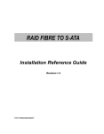
RAID 0 is typically defined as a group of striped disk drives without parity or data
redundancy. RAID 0 arrays can be configured with large stripes for multi-user
environments or small stripes for single-user systems that access long sequential
records. RAID 0 arrays deliver the best data storage efficiency and performance
of any array type. The diFAdvantage is that if one drive in a RAID 0 array fails, the
entire array fails.
1-4
Introduction
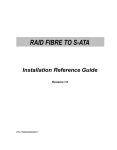
RAID 1, also known as disk mirroring, is simply a pair of disk drives that store
duplicate data but appear to the computer as a single drive. Although striping is
not used within a single mirrored drive pair, multiple RAID 1 arrays can be striped
together to create a single large array consisting of pairs of mirrored drives. All
writes must go to both drives of a mirrored pair so that the information on the
drives is kept identical. However, each individual drive can perform simultaneous,
independent read operations. Mirroring thus doubles the read performance of a
single non-mirrored drive and while the write performance is unchanged. RAID 1
delivers the best performance of any redundant array type. In addition, there is
less performance degradation during drive failure than in RAID 5 arrays.
Introduction
1-5
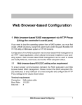
RAID 3 sector-stripes data across groups of drives, but one drive in the group is
dedicated to storing parity information. RAID 3 relies on the embedded ECC in
each sector for error detection. In the case of drive failure, data recovery is
accomplished by calculating the exclusive OR (XOR) of the information recorded
on the remaining drives. Records typically span all drives, which optimizes the
disk transfer rate. Because each I/O request accesses every drive in the array,
RAID 3 arrays can FAtisfy only one I/O request at a time. RAID 3 delivers the
best performance for single-user, single-tasking environments with long records.
Synchronized-spindle drives are required for RAID 3 arrays in order to avoid
performance degradation with short records. RAID 5 arrays with small stripes
can yield similar performance to RAID 3 arrays.
Under RAID 5 parity information is distributed across all the drives. Since there
is no dedicated parity drive, all drives contain data and read operations can be
overlapped on every drive in the array. Write operations will typically access one
data drive and one parity drive. However, because different records store their
parity on different drives, write operations can usually be overlapped.
1-6
Introduction
RAID 6 is similar to RAID 5 in that data protection is achieved by writing parity
information to the physical drives in the array. With RAID 6, however, two sets of
parity data are used. These two sets are different, and each set occupies a
capacity equivalent to that of one of the constituent drives. The main advantages
of RAID 6 is High data availability – any two drives can fail without loss of critical
data.
Introduction
1-7
Dual-level RAID achieves a balance between the increased data availability
inherent in RAID 1 and RAID 5 and the increased read performance inherent in
disk striping (RAID 0). These arrays are sometimes referred to as RAID 0+1 or
RAID 10 and RAID 0+5 or RAID 50.
In summary:
v
v
v
v
v
1-8
RAID 0 is the fastest and most efficient array type but offers no faulttolerance. RAID 0 requires a minimum of two drives.
RAID 1 is the best choice for performance-critical, fault-tolerant
environments. RAID 1 is the only choice for fault-tolerance if no more than
two drives are used.
RAID 3 can be used to speed up data transfer and provide fault-tolerance
in single-user environments that access long sequential records. However,
RAID 3 does not allow overlapping of multiple I/O operations and requires
synchronized-spindle drives to avoid performance degradation with short
records. RAID 5 with a small stripe size offers similar performance.
RAID 5 combines efficient, fault-tolerant data storage with good
performance characteristics. However, write performance and performance
during drive failure is slower than with RAID 1. Rebuild operations also
require more time than with RAID 1 because parity information is also
reconstructed. At least three drives are required for RAID 5 arrays.
RAID 6 is essentially an extension of RAID level 5 which allows for
additional fault tolerance by using a second independent distributed parity scheme (two-dimensional parity). Data is striped on a block level
across a set of drives, just like in RAID 5, and a second set of parity is
calculated and written across all the drives; RAID 6 provides for an
extremely high data fault tolerance and can sustain multiple simultaneous drive failures. Perfect solution for mission critical applications.
Introduction
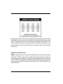
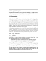
RAID Management
The subsystem can implement several different levels of RAID technology.
RAID levels supported by the subsystem are shown below.
RAID
Level
0
1
3
5
6
0 + 1
Description
Min
Drives
Block striping is provide, which yields higher performance than with
individual drives. There is no redundancy.
2
Drives are paired and mirrored. All data is 100% duplicated on an
equivalent drive. Fully redundant.
2
Data is striped across several physical drives. Parity protection is
used for data redundancy.
3
Data is striped across several physical drives. Parity protection is
used for data redundancy.
3
Data is striped across several physical drives. Parity protection is
used for data redundancy. Requires N+2 drives to implement
because of two-dimensional parity scheme
4
Combination of RAID levels 0 and 1. This level provides striping
and redundancy through mirroring.
4
Introduction
1-9
1.3
Fibre Functions
1.3.1 Overview
Fibre Channel is a set of standards under the auspices of ANSI (American
National Standards Institute). Fibre Channel combines the best features from
SCSI bus and IP protocols into a single standard interface, including highperformance data transfer (up to 200 MB per second), low error rates, multiple connection topologies, scalability, and more. It retains the SCSI command-set functionality, but use a Fibre Channel controller instead of a SCSI
controller to provide the network interface for data transmission. In today’s
fast-moving computer environments, Fibre Channel is the serial data transfer
protocol choice for high-speed transportation of large volumes of information
between workstation, server, mass storage subsystems, and peripherals.
Physically, the Fibre Channel can be an interconnection of multiple communication points, called N_Ports. The port itself only manages the connection
between itself and another such end-port which, which could either be part of
a switched network, referred to as a Fabric in FC terminology, or a point-topoint link. The fundamental elements of a Fibre Channel Network are Port
and node. So a node can be a computer system, storage device, or Hub/
Switch.
This chapter describes the Fibre-specific functions available in the Fibre
channel RAID controller. Optional functions have been implemented for Fibre
channel operation only available in the Web browser-based RAID manager.
The LCD and VT-100 can’t configure the options available for Fibre
channel RAID controller.
1.3.2 Three ways to connect (FC Topologies)
A topology defines the interconnection scheme. It defines the number of devices that can be connected. Fibre Channel supports three different logical or
physical arrangements (topologies) for connecting the devices into a network:
l
Point-to-Point
l
Arbitrated Loop(AL)
1-10
Introduction
l
Switched (Fabric)
The physical connection between devices varies from one topology to another. In all of these topologies, a transmitter node in one device sends information to a receiver node in another device. Fibre Channel networks can use
any combination of point-to-point, arbitrated loop(FC_AL), and switched fabric
topologies to provide a variety of device sharing options.
Point-to-point
A point-to-point topology consists of two and only two devices connected by
N-ports of which are connected directly. In this topology, the transmit Fibre of
one device connects to the receiver Fibre of the other device and vice verFA.
The connection is not shared with any other devices. Simplicity and use of
the full data transfer rate make this Point-to-point topology an ideal extension
to the standard SCSI bus interface. The point-to-point topology extends SCSI
connectivity from a server to a peripheral device over longer distances.
Arbitrated Loop
The arbitrated loop (FC_AL) topology provides a relatively simple method of
connecting and sharing resources. This topology allows up to 126 devices or
nodes in a single, continuous loop or ring. The loop is constructed by daisychaining the transmit and receive cables from one device to the next or by
using a hub or switch to create a virtual loop. The loop can be self-contained
or incorporated as an element in a larger network. Increasing the number of
devices on the loop can reduce the overall performance of the loop because
the amount of time each device can use the loop is reduced. The ports in an
arbitrated loop are referred as L-Ports.
Switched Fabric
A switched fabric a term is used in a Fibre channel to describe the generic
switching or routing structure that delivers a frame to a destination based on
the destination address in the frame header. It can be used to connect up to
16 million nodes, each of which is identified by a unique, world-wide name.
In a switched fabric, each data frame is transferred over a virtual point-to-
Introduction
1-11
point connection. There can be any number of full-bandwidth transfers occurring through the switch. Devices do not have to arbitrate for control of the
network; each device can use the full available bandwidth.
A fabric topology contains one or more switches connecting the ports in the
FC network. The benefit of this topology is that many devices (approximately
2-24) can be connected. A port on a Fabric switch is called an F-Port (Fabric
Port). Fabric switches can function as an alias server, Multicast server,
broadcast server, quality of service facilitator and directory server as well.
1.3.3 Basic elements
The following elements are the connectivity of storages and Server components using the Fibre channel technology.
Cables and connectors
There are different types of cables of varies lengths for use in a Fibre Channel configuration. Two types of cables are supported : Copper and optical
(fiber). Copper cables are used for short distances and transfer data up to 30
meters per link. Fiber cables come in two distinct types: Multi-Mode
fiber(MMF) for short distances (up to 2km), and Single-Mode Fiber(SMF) for
longer distances (up to 10 kilometers). The controller default supports two
short wave multi-mode fibre optical SFP connectors.
Fibre Channel Adapter
Fibre Channel Adapter is devices that connect to a workstation, or server and
control the electrical protocol for communications.
Hubs
Fibre Channel hubs are used to connect up to 126 nodes into a logical loop.
All connected nodes share the bandwidth of this one logical loop. Each port
on a hub contains a Port Bypass Circuit(PBC) to automatically open and
close the loop to support hot pluggability.
Switched Fabric
Switched fabric is the highest performing device available for interconnecting
large numbers of devices, increasing bandwidth, reducing congestion and
1-12
Introduction
providing aggregate throughput.
Each device connected to a port on the switch, enabling an on-demand connection to every connected device. Each node on a Switched fabric uses an
aggregate throughput data path to send or receive data.
1.3.4 LUN Masking
LUN masking is a RAID system-centric enforced method of masking multiple
LUNs behind a single port. By using World Wide Port Names (WWPNs) of
server HBAs, LUN masking is configured at the RAID-array level. LUN masking also allows disk storage resource sharing across multiple independent
servers. A single large RAID device can be sub-divided to serve a number of
different hosts that are attached to the RAID through the FAN fabric with LUN
masking. So that only one or a limited number of servers can see that LUN,
each LUN inside the RAID device can be limited.
LUN masking can be done either at the RAID device (behind the RAID port)
or at the server HBA. It is more secure to mask LUNs at the RAID device,
but not all RAID devices have LUN masking capability. Therefore, in order to
mask LUNs, some HBA vendors allow persistent binding at the driver-level.
1.4 Array Definition
1.4.1 RAID Set
A RAID Set is a group of disks containing one or more Volume Sets. It has
the following features in the RAID subsystem controller:
1. Up to eight RAID Sets are supported per RAID subsystem controller.
2. From one to eight drives can be included in an individual RAID Set.
3. It is impossible to have multiple RAID Sets on the same disks.
A Volume Set must be created either on an existing RAID Set or on a group
of available individual disks (disks that are not yet a part of an RAID Set). If
there are pre-existing RAID Sets with available capacity and enough disks for
specified RAID level desired, then the Volume Set will be created in the existing RAID Set of the user’s choice. If physical disks of different capacity are
grouped together in a RAID Set, then the capacity of the smallest disk will
become the effective capacity of all the disks in the RAID Set.
Introduction
1-13
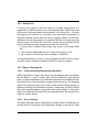
1.4.2 Volume Set
A Volume Set is seen by the host system as a single logical device. It is
organized in a RAID level with one or more physical disks. RAID level refers
to the level of data performance and protection of a Volume Set. A Volume
Set capacity can consume all or a portion of the disk capacity available in a
RAID Set. Multiple Volume Sets can exist on a group of disks in a RAID Set.
Additional Volume Sets created in a specified RAID Set will reside on all the
physical disks in the RAID Set. Thus each Volume Set on the RAID Set will
have its data spread evenly across all the disks in the RAID Set.
1. Volume Sets of different RAID levels may coexist on the same RAID
Set.
2. The maximum addressable size of a single Volume Set is 2 TB.
3. Up to sixty-four Volume Sets can be created in a RAID Set.
In the illustration below, Volume 1 can be assigned a RAID 5 level of operation while Volume 0 might be assigned a RAID 0+1 level of operation.
1.4.3 Easy of Use features
1.4.3.1 Instant Availability/Background Initialization
RAID 0 and RAID 1 Volume Sets can be used immediately after the creation.
But the RAID 3, 5 and 6 Volume Sets must be initialized to generate the
parity. In Normal Initialization, the initialization proceeds as a background task,
the Volume Set is fully accessible for system reads and writes. The operating
system can instantly access to the newly created arrays without requiring a
reboot and waiting the initialization complete. Furthermore, the RAID Volume
Set is also protected against a single disk failure while initialing. In Fast Initialization, the initialization process must be completed before the Volume Set is
ready for system access.
1.4.3.2 Array Roaming
The RAID subsystem stores configuration information both in NVRAM and on
the disk drives It can protect the configuration settings in the case of a disk
1-14
Introduction
drive or controller failure. Array roaming allows the administrators the ability to
move a RAID Set to another system without losing RAID configuration and
data on that RAID Set. If a server fails to work, the RAID Set disk drives can
be moved to another server and inserted in any order.
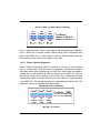
1.4.3.3 Online Capacity Expansion
Online Capacity Expansion makes it possible to add one or more physical
drive to a Volume Set, while the server is in operation, eliminating the need to
store and restore after reconfiguring the RAID Set. When disks are added to
a RAID Set, unused capacity is added to the end of the RAID Set. Data on
the existing Volume Sets residing on that RAID Set is redistributed evenly
across all the disks. A contiguous block of unused capacity is made available
on the RAID Set. The unused capacity can create additional Volume Set. The
expansion process is illustrated as following figure.
Introduction
1-15
The RAID subsystem controller redistributes the original Volume Set over the
original and newly added disks, using the FAme fault-tolerance configuration.
The unused capacity on the expand RAID Set can then be used to create an
additional Volume Sets, with a different fault tolerance setting if user need to
change.
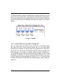
1.4.3.4 Online RAID Level and Stripe Size Migration
User can migrate both the RAID level and stripe size of an existing Volume
Set, while the server is online and the Volume Set is in use. Online RAID
level/stripe size migration can prove helpful during performance tuning activities as well as in the event that additional physical disks are added to the
RAID subsystem. For example, in a system using two drives in RAID level 1,
you could add capacity and retain fault tolerance by adding one drive. With
the addition of third disk, you have the option of adding this disk to your existing RAID logical drive and migrating from RAID level 1 to 5. The result would
be parity fault tolerance and double the available capacity without taking the
system off.
1-16
Introduction
1.4.4 High availability
1.4.4.1 Creating Hot Spares
A hot spare drive is an unused online available drive, which is ready for replacing the failed disk drive. In a RAID level 1, 0+1, 3, 5 or 6 RAID Set, any
unused online available drive installed but not belonging to a RAID Set can be
defined as a hot spare drive. Hot spares permit you to replace failed drives
without powering down the system. When SurfRAID TRITON 8FA detects a
drive failure, the system will automatically and transparently rebuild the RAID
Set using the hot spare (drives). The RAID Set will be reconfigured and rebuilt in the background, while the SurfRAID TRITON 8FA continues to handle
system requests. During the automatic rebuild process, system activity will
continue as normal, however, the system performance and fault tolerance will
be affected.
Important:
The hot spare must have at least the same or more capacity as the
drive it replaces.
1.4.4.2 Hot-Swap Disk Drive Support
The RAID subsystem has built the protection circuit to support the replacement of hard disk drives without having to shut down or reboot the system.
The removable hard drive tray can deliver “hot swappable,” fault-tolerant
RAID solutions at prices much less than the cost of conventional SCSI hard
disk RAID subsystems. We provide this feature for subsystems to provide
the advanced fault tolerant RAID protection and “online” drive replacement.
1.4.4.3 Hot-Swap Disk Rebuild
A Hot-Swap function can be used to rebuild disk drives in arrays with data
redundancy such as RAID level 1(0+1), 3, 5 and 6. If a hot spare is not
available, the failed disk drive must be replaced with a new disk drive so that
the data on the failed drive can be rebuilt. If a hot spare is available, the
rebuild starts automatically when a drive fails. The RAID subsystem auto-
Introduction
1-17
matically and transparently rebuilds failed drives in the background with userdefinable rebuild rates. The RAID subsystem will automatically restart the
system and the rebuild if the system is shut down or powered off abnormally
during a reconstruction procedure condition. When a disk is Hot Swap, although the system is functionally operational, the system may no longer be
fault tolerant. Fault tolerance will be lost until the removed drive is replaced
and the rebuild operation is completed.
1-18
Introduction
Chapter 2
Getting Started
Getting started with the SurfRAID TRITON 8FA consists of the
following steps:
1. Unpack the SurfRAID TRITON 8FA.
2. Identifying Parts of the SurfRAID TRITON 8FA.
3. Install Hard Drives.
4. Connect the Fibre Cables.
5. Power on the SurfRAID TRITON 8FA.
2.1
Unpacking the Subsystem
Before continuing, first unpack the subsystem and verify that the contents of
the shipping carton are all there and in good condition. Before removing the
subsystem from the shipping carton, visually inspect the physical condition of
the shipping carton. Exterior damage to the shipping carton may indicate that
the contents of the carton are damaged.
Getting Started
2-1
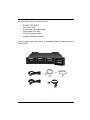
The package contains the following items:
•
•
•
•
•
•
SurfRAID TRITON 8FA
Two power cords
One external null modem cable
One external UPS cable
One RJ-45 ethernet cable
Installation Reference Guide
If any of these items are missing or damaged, please contact Partners at
800-550-3005
Getting Started
2-2
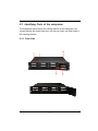
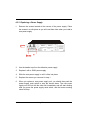
2.2 Identifying Parts of the subsystem
The illustrations below identify the various features of the subsystem. Get
yourself familiar with these terms as it will help you when you read further in
the following sections.
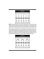
2.2.1 Front View
Getting Started
2-3
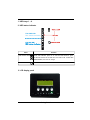
1. HDD trays 1 ~ 8
2. HDD status Indicator
Function
Parts
HDD Status LEDs
Green LED indicates power is on and hard drive status is good
for this slot. If there is no hard drive, the LED is red. If hard drive
defective/failed, the LED is orange.
HDD access LEDs
These LED will blink blue when the hard drive is accessed.
3. LCD display panel
Getting Started
2-4
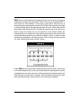
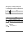
4. Smart Function Panel - Function Keys for RAID configuration
The smart LCD panel is where you will configure the RAID subsystem. If you
are configuring the subsystem using the LCD panel, please press the controller button to configure your RAID subsystem.
Parts
Function
Up and Down
arrow buttons
Use the Up or Down arrow keys to go through the information
on the LCD screen. This is also used to move between each
menu when you configure the subsystem.
Select button
This is used to enter the option you have selected.
Exit button
Press this button to return to the previous menu.
5. Environment status
Parts
Voltage warning
LED
Function
If the output DC voltage is over or under +3.3V, +5V or +12V, an
alarm will sound warning of a voltage abnormality and this LED
will turn red. (+3.3V: +-5%, +5V: +-5% , +12V: +-10%)
Fan fail LED
If temperature irregularity in these systems occurs (HDD slot temperature over 55o C), this LED will turn red and an alarm will
sound.
When a fan’s rotation speed is lower than 2600rpm, this LED will
turn red and an alarm will sound.
Power fail LED
If a redundant power supply fails, this LED will turn red and an
alarm will sound.
Power LED
Green LED indicates power is on.
Access LED
Blue blinking LED indicates data is being accessed.
Over temp
LED
Getting Started
2-5
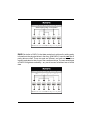
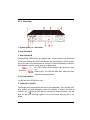
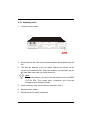
2.2.2 Rear View
1. System power on / off switch
2. Host Channel A
3. Host Channel B
The SurfRAID TRITON 8FA is equipped with 2 host channels (Host channel
A and Host channel B). Each host channel with one optical LC Fibre connectors at the rear of the subsystem for connect to Fibre Hub/Switch or Server’s
fibre interface, another one is reserve for daisy chain.
Link LED: Green LED indicates Fibre channel is linking.
Activity LED: The LED will blink blue when the Fibre
channel is being accessed.
4. Fan Fail indicator
If a fan fails, this LED will turn red.
5. Cooling Fan module
Two blower fans are located at the rear of the subsystem. They provide sufficient airflow and heat dispersion inside the chassis. In case a fan fails to
function, the “ ” Fan fail LED will turn red and an alarm will sound. You will
also see an error mesFAge appear in the LCD screen warning you of fan
failure.
Getting Started
2-6
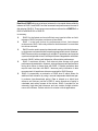
6. Power Supply Alarm Reset button
You can push the power supply reset button to stop the power supply buzzer
alarm.
7. AC power input socket 1 ~ 2 (From left to right)
8. Power Supply Unit 1 ~ 2 (From left to right)
Three power supplies (power supply 1 and power supply 2) are located at
the rear of the SurfRAID TRITON 8FA. Turn on the power of these power
supplies to power-on the SurfRAID TRITON 8FA. The “power” LED at the
front panel will turn green.
If a power supply fails to function or a power supply was not turned on, the
“ ” Power fail LED will turn red and an alarm will sound. An error mesFAge
will also appear on the LCD screen warning of power failure.
9. R-Link Port : Remote Link through RJ-45 ethernet for remote management
The SurfRAID TRITON 8FA is equipped with one 10/100 Ethernet RJ45 LAN
port. You use web-based browser to management SurfRAID TRITON 8FA
through Ethernet for remote configuration and monitoring.
Link LED: Green LED indicates ethernet is linking.
Link speed LED: Orange LED indicates the link speed is 100Mbps. The LED
will not blink when the link speed is 10Mbps.
10. Uninterrupted Power Supply (UPS) Port
The SurfRAID TRITON 8FA may come with an optional UPS port allowing
you to connect a UPS device. Connect the cable from the UPS device to the
UPS port located at the rear of the SurfRAID TRITON 8FA. This will automatically allow the SurfRAID TRITON 8FA to use the functions and features of the
UPS.
11. Monitor Port
The SurfRAID TRITON 8FA is equipped with a serial monitor port allowing
you to connect a PC or terminal.
Getting Started
2-7
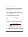
2.3 Connecting to Fibre HBA
The subsystem supports fibre interface which provides fast 200MB data
transfer rate using fibre. This section describes the location of the host
channels and instructions on connecting external fibre devices.
1. Configure the Loop ID of subsystem or use dynamic LIP.
2. For every pair of host channel fibre connector at the rear of the subsystem, attach one end of the fibre optical cable to one of the fibre
connectors and the other end to the host adapter’s external fibre connector or to the fibre Hub/Switch.
3. Connect the other host system using the other fibre optical cable if you
want to configure subsystem into multi-host attachment.
Note:
Connect the RX of the fibre connectors to the TX of host adapter’s
external fibre connector or to the fibre Hub/Switch. Contrariwise,
Connect the TX of the fibre connectors to the RX of host adapter’s
external fibre connector or to the fibre Hub/Switch.
Note:
For safety reasons, make sure the Disk Array and Host Computer
are turned off when you plug-in the Fibre cable.
Getting Started
2-8
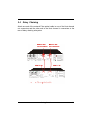
2.4
Daisy Chaining
Attach one end of the external Fibre optical cable to one of the Host channel
out connectors and the other end to the Host channel in connectors at the
rear of daisy chaining subsystem.
Getting Started
2-9
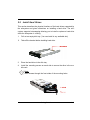
2.5 Install Hard Drives
This section describes the physical locations of the hard drives supported by
the subsystem and gives instructions on installing a hard drive. The subsystem supports hot-swapping allowing you to install or replace a hard drive
while the subsystem is running.
1.
Pull out an empty disk tray. (You can install in any available slot.)
2.
Take off the bracket before installing hard drive.
3.
Place the hard drive in the disk tray.
4.
Install the mounting screws on each side to secure the drive in the mobile rack.
Note:
Insert screws through the front sides of the mounting holes.
Getting Started
2-10
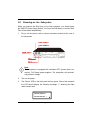
2.6
Powering-on the Subsystem
When you connect the Disk Array to the Host computer, you should press
the ON/OFF Power Supply Switch. It will turn the Disk Array on and the SelfTest will be started automatically.
1.
Plug in all the power cords or power connectors located at the rear of
the subsystem.
Note:
The subsystem is equipped with redundant PFC (power factor correction), Full Range power supplies. The subsystem will automatically selector voltage.
2.
Turn on the power.
3.
The “Power” LED on the front panel will turn green. After a few moments
the LCD should display the following message: “ ” detecting the fibre
*
cable connect well.
{Model Name}
xxx.xxx.xxx.xxx *
Getting Started
2-11
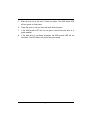
5.
Slide the tray into a slot until it clicks into place. The HDD status LED
will turn green on front panel.
6.
Press the lever in until you hear the latch click into place.
7.
If the HDD power LED did not turn green, check the hard drive is in
good condition.
8.
If the hard drive is not being accessed, the HDD access LED will not
illuminate. The LED blinks only when being accessed.
Getting Started
2-12
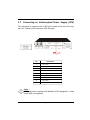
2.7
Connecting an Uninterrupted Power Supply (UPS)
The subsystem is equipped with a UPS port located at the rear of the system unit. It allows you to connect a UPS fail signal.
Pin
Description
1
Not used
2
UPS Line Fail
3
Not used
4
UPS Common
5
Not used
6
Not used
7
Not used
8
Not used
9
Not used
Note:
UPS connection compliant with NetWare UPS management - smart
mode UPS not supported.
Getting Started
2-13
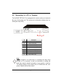
2.8 Connecting to a PC or Terminal
The SurfRAID TRITON 8 FA is equipped with a serial monitor port located at
the rear of the system unit. This serves as an alternative display when accessing the setup utility.
Pin
Description
1
Data Carrier Detect (DCD)
2
Receive Data (RD)
3
Transmit Data (TD)
4
Data Teminal Ready (DTR)
5
Signal Ground (SG)
6
Data Set Ready (DSR)
7
Ready To Send (RTS)
8
Clear To Send (CTS)
9
Ring Indicator (RI)
Note:
Refer to Chapter 3 for instructions on accessing the setup utility
through a PC or terminal, as well as instructions on setting the
baud rate, stop bit, data bit and parity of your monitor or terminal.
The default setting of the monitor port is 115200 baud rate, nonparity, 8 data bit and no flow control.
Getting Started
2-14
Chapter 3
Configuring
The SurfRAID TRITON 8FA has a setup configuration utility built in containing
important information about the configuration as well as settings for various
optional functions in the SurfRAID TRITON 8FA. This chapter explains how to
use and make changes to the setup utility.
Configuration Methods
There are three methods of configuring the SurfRAID TRITON 8FA. You may
configure through the following methods:
• VT100 terminal connected through the controller’s serial port
• Front panel touch-control keypad
• Web browser-based Remote RAID management via the R-Link ethernet
port
Important:
The SurfRAID TRITON 8FA allows you to access the utility using only
one method at a time. You cannot use both methods at the same
time.
3.1
Configuring through a Terminal
Configuring through a terminal will allow you to use the same configuration
options and functions that are available from the LCD panel. To start-up:
Configuring
3-1
1.
Connect a VT100 compatible terminal or a PC operating in an equivalent terminal emulation mode to the monitor port located at the rear of
the SurfRAID TRITON 8FA.
Note:
You may connect a terminal while the SurfRAID TRITON 8FA’s
power is on.
2.
Power-on the terminal.
3.
Run the VT100 program or an equivalent terminal program.
3-2
Configuring
4.
The default setting of the monitor port is 115200 baud rate, 8 data bit,
non-parity, 1 stop bit and no flow control.
Configuring
3-3
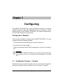
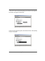
5.
Click
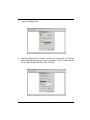
6.
Open the File menu, and then open Properties.
3-4
disconnect button.
Configuring
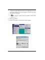
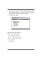
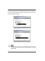
7.
8.
Open the Settings Tab.
Open the Settings Tab. Function, arrow and ctrl keys act as: Terminal
Keys, Backspace key sends: Crtl+H, Emulation: VT100, Telnet terminal:
VT100, Back scroll buffer lines: 500. Click OK.
Configuring
3-5
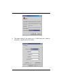
9.
Now, the VT100 is ready to use. After you have finished the VT100 Terminal setup, you may press “ X “ key (in your Terminal) to link the SurfRAID TRITON 8FA and Terminal together. Press “X’ key to display the
disk array Monitor Utility screen on your VT100 Terminal.
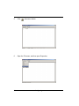
10. The Main Menu will appear.
Keyboard Function Key Definitions
“ A “ key - to move to the line above
“ Z “ key - to move to the next line
“ Enter “ key - Submit selection function
“ ESC “ key - Return to previous screen
“ L ” key - Line draw
“ X ” key - Redraw
3-6
Configuring
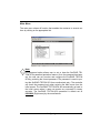
Main Menu
The main menu shows all function that enables the customer to execute actions by clicking on the appropriate link.
Note:
The password option allows user to set or clear the SurfRAID TRITON 8FA’s password protection feature. Once the password has been
set, the user can only monitor and configure the SurfRAID TRITON
8FA by providing the correct password. The password is used to protect the SurfRAID TRITON 8FA from unauthorized entry. The controller
will check the password only when entering the Main menu from the
initial screen. The SurfRAID TRITON 8FA will automatically go back to
the initial screen when it does not receive any command in twenty
seconds. The SurfRAID TRITON 8FA password is default set at
00000000 (Eight zeros) by the manufacturer.
Configuring
3-7
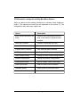
VT100 terminal configuration Utility Main Menu Options
Select an option and the related information or submenu items display beneath it. The submenus for each item are explained on the section 3.3. The
configuration utility main menu options are:
Option
Description
Quick Volume And RAID Set
Setup
Create a RAID configuration that consists of the number of physical disks
installed
RAID Set Functions
Create a customized RAID Set
Volume Set Functions
Create a customized Volume Set
Physical Drive Functions
View individual disk information
RAID System Functions
Setting the RAID system configurations
Fibre Channel Config
Setting the Fibre Channel configurations
Ethernet Configuration
Setting the Ethernet configurations
View System Events
View all system events in the buffer
Clear Event Buffer
Clear all event buffer information
Hardware Monitor
Show system environment status
System Information
View the controller information
3-8
Configuring
3.2 Configuring the SurfRAID TRITON 8FA Using the
LCD Panel
The LCD Display front panel function keys are the primary user interface for
the SurfRAID TRITON 8FA. Except for the “Firmware update” all configuration
can be performed through this interface.The LCD provides a system of
screens with areas for information, status indication, or menus. The LCD
screen displays up to two lines at a time of menu items or other information.
The SurfRAID TRITON 8FA password is default setting at 00000000 (Eight
zeros) by the manufacturer.
Function Key Definitions
The four function keys at the top of the front panel perform the following functions :
Parts
Function
Up or Down
arrow buttons
Use the Up or Down arrow keys to go through the information
on the LCD screen. This is also used to move between each
menu when you configure the subsystem.
Select button
This is used to enter the option you have selected.
Exit button
Press this button to return to the previous menu.
Configuring
3-9
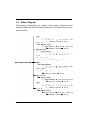
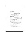
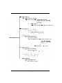
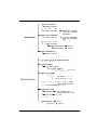
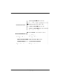
3.3
Menu Diagram
The following tree diagram is a summary of the various configuration and
setting functions that can be accessed through the LCD panel menus or the
terminal monitor.
3-10
Configuring
Configuring
3-11
3-12
Configuring
Configuring
3-13
3-14
Configuring
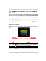
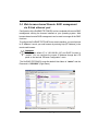
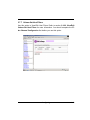
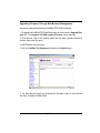
3.4 Web browser-based Remote RAID management
via R-Link ethernet port
Configuration of the SurfRAID TRITON 8FA can be completed with remote RAID
management utilizing the browser installed on your operating system. Web
browser-based remote RAID management can be used to manage all the RAID
functions.
To configure the SurfRAID TRITON 8FA on a remote machine, you need to know
its IP Address. Launch your web browser by entering http://[IP Address] in the
remote web browser.
Important:
The Ethernet default IP is “192.168.001.100” and DHCP function is
“enable”. You can configure the correct IP Address through the LCD
panel or the terminal “Ethernet Configuration” menu.
The SurfRAID TRITON 8FA controller default User Name is “admin” and the
Password is “00000000” (Eight Zeros).
Configuring
3-15
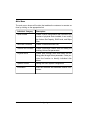
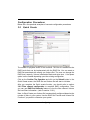
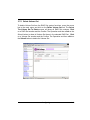
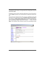
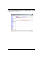
Main Menu
The main menu shows all function that enables the customer to execute actions by clicking on the appropriate link.
Individual Category
Description
Quick Create
Create a RAID configuration that consists of the
number of physical disks installed; it can modify
the Volume Set Capacity, RAID Level, and Stripe
Size.
RAID Set Functions
Create a customized RAID Set.
Volume Set Functions
Create customized Volume Sets and modify the
existing Volume Set parameters.
Physical Drive
Create pass through disks and modify the existing pass through drives parameter. It also provides the function to identify individual disk
drives.
System Control
Setting the RAID system configuration
Information
View the controller and hardware monitor information.
3-16
Configuring
Configuration Procedures
Below are a few practical examples of concrete configuration procedures.
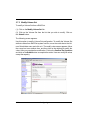
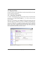
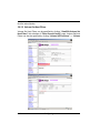
3.5
Quick Create
The number of physical drives in the SurfRAID TRITON 8FA determines the
RAID levels that can be implemented with the RAID Set. You can create a
RAID Set associated with exactly one Volume Set. The user can change the
RAID level, capacity, Volume Initialization Mode and stripe size . A hot spare
option is also created depending upon the existing configuration.
Click on the Confirm The Operation and click on the Submit button in the
Quick Create screen, the RAID Set and Volume Set will start to initialize.
After you complete the Quick create function, you should refer to section
3.9.2 Fibre channel configuration to complete RAID configuration. Then
you can use RAID Set Hierarchy feature to view the fibre channel Volume
Set host filters information (refer to section 3.10.1).
Note: In Quick Create your Volume Set is automatically configured based on the
number of disks in your system. Use the RAID Set Function and Volume Set
Function if you prefer to customize your system.
Configuring
3-17
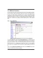
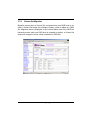
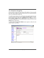
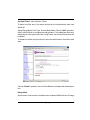
3.6 RAID Set Functions
Use the RAID Set Function and Volume Set Function if you prefer to customize your system. Manual configuration allows full control of the RAID Set setting, but it will take longer to complete than the Quick Volume/RAID Setup
configuration. Select the RAID Set Function to manually configure the RAID
Set for the first time or to delete an existing RAID Set and reconfigure a new
RAID Set. A RAID Set is a group of disks containing one or more Volume
Sets.
3.6.1 Create RAID Set
To create a RAID Set, click on the Create RAID Set link. A “Select The IDE
Drive For RAID Set” screen is displayed showing the IDE drive connected to
the current controller. Click on the selected physical drives with the current
RAID Set. Enter 1 to 15 alphanumeric characters to define a unique identifier
for a RAID Set. The default RAID Set name will always appear as RAID Set
#.
Click on the Confirm The Operation and click on the Submit button in the
screen, the RAID Set will start to initialize.
3-18
Configuring
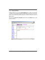
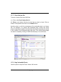
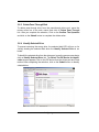
3.6.2 Delete RAID Set
To delete a RAID Set, click on the Delete RAID Set link. A “Select The RAID SET
To Delete” screen is displayed showing all RAID Sets existing in the current controller. Click the RAID Set number you which to delete in the select column to
delete screen.
Click on the Confirm The Operation and click on the Submit button in the
screen to delete it.
Configuring
3-19
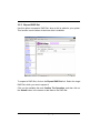
3.6.3 Expand RAID Set
Use this option to expand a RAID Set, when a disk is added to your system.
This function is active when at least one drive is available.
To expand a RAID Set, click on the Expand RAID Set link. Select the target
RAID Set, which you want to expand it.
Click on the available disk and Confirm The Operation, and then click on
the Submit button in the screen to add disks to the RAID Set.
3-20
Configuring
Note:
1. Once the Expand RAID Set process has started, user cannot
stop it. The process must be completed.
2. If a disk drive fails during RAID Set expansion and a hot spare
is available, an auto rebuild operation will occur after the RAID Set
expansion completes.
Migrating occurs when a disk is added to a RAID Set. Migration status is
displayed in the RAID status area of the RAID Set information when a disk is
added to a RAID Set. Migrating status is also displayed in the associated
volume status area of the Volume Set Information when a disk is added to a
RAID Set.
Configuring
3-21
3.6.4
Activate Incomplete RAID Set
When one of the disk drives is removed in power-off state, the RAID Set status
will change to “Incomplete State”. When the SurfRAID TRITON 8FA
is powered on again, the RAID Set can be activated using the “Activate RAID
Set” option. Once activated the RAID State will change to Degraded Mode.
To activate the incomplete the RAID Set, click on the Activate RAID Set link. A
“Select The RAID SET To Activate” screen is displayed showing all RAID
Sets
existing in the current controller. Click the RAID Set number you wish to activate in the select column.
3-22
Configuring
Click on the Submit button on the screen to activate the RAID Set that has a
removed disk - in the power off state. The SurfRAID TRITON 8SA will continue to work in degraded mode.
Configuring
3-23
3.6.5 Create Hot Spare
When you choose the Create Hot Spare option in the RAID Set Function, all
unused physical devices connected to the current controller appear: Select
the target disk by clicking on the appropriate check box. Click on the Confirm
The Operation, and click on the Submit button in the screen to create the
hot spares.
The create Hot Spare option gives you the ability to define a global hot spare.
3.6.6 Delete Hot Spare
Select the target Hot Spare disk to delete by clicking on the appropriate
check box.
Click on the Confirm The Operation, and click on the Submit button in the
screen to delete the hot spares.
3-24
Configuring
3.6.7 Rescue RAID Set
If you need to rescue the missing RAID Set, please contact our engineer for
assistance.
Configuring
3-25
3.7 Volume Set Function
A Volume Set is seen by the host system as a single logical device. It is
organized in a RAID level with one or more physical disks. RAID level refers
to the level of data performance and protection of a Volume Set. A Volume
Set capacity can consume all or a portion of the disk capacity available in a
RAID Set. Multiple Volume Sets can exist on a group of disks in a RAID Set.
Additional Volume Sets created in a specified RAID Set will reside on all the
physical disks in the RAID Set. Thus each Volume Set on the RAID Set will
have its data spread evenly across all the disks in the RAID Set.
3.7.1 Create Volume Set
The following are the Volume Set features:
1.Volume Sets of different RAID levels may coexist on the same RAID Set.
2.Up to 16 Volume Sets in a RAID Set can be created by the SurfRAID TRITON 8FA controller.
3. The maximum addressable size of a single Volume Set is 2 TB.
To create a Volume Set from RAID Set system, move the cursor bar to the
main menu and click on the Create Volume Set link. The Select The RAID
Set To Create On It screen will show all RAID Set number. Click on a
RAID Set number that you want to create and then click on the Submit button.
Modify Volume Set allows the user to select the Volume name, capacity,
RAID level, stripe size, fiibre channel/LUN, cache mode and tag queuing.
3-26
Configuring
Volume Name:
The default volume name will always appear as Volume Set #. You can
rename the Volume Set name providing it does not exceed the 15 character
limit.
RAID Level:
Set the RAID level for the Volume Set. Highlight RAID Level and press Enter.
The available RAID levels for the current Volume Set are displayed. Select a
RAID level and press Enter to confirm.
Capacity:
The maximum volume size is the default in the first setting. Enter the appropriate
volume size to fit your application.
Initialization Mode:
Set the Initialization Mode for the Volume Set. Foreground mode is faster
Configuring
3-27
completion and background is instant availability.
Stripe Size:
This parameter sets the size of the stripe written to each disk in a RAID 0, 1,
0+1, or 5 logical drive. You can set the stripe size to 4 KB, 8 KB, 16 KB, 32
KB, 64 KB, or 128 KB.
A larger stripe size produces better-read performance, especially if your computer does mostly sequential reads. However, if you are sure that your computer does random reads more often, select a small stripe size
Note: RAID level 3 can’t modify the stripe size.
Cache Mode:
The SurfRAID TRITON 8FA supports Write-Through Cache and Write-Back
Cache.
Tag Queuing:
The Enabled option is useful for enhancing overall system performance under
multi-tasking operating systems. The Command Tag (Drive Channel) function
controls the Fibre command tag queuing support for each drive channel. This
function should normally remain enabled. DiFAble this function only when using
older Fibre drives that do not support command tag queuing
Fibre Channel/LUN Base/LUN:
Fibre Channel: Two 2Gbps Fibre channel can be applied to the internal SurfRAID TRITON 8FA. Choose the Fibre Host# option 0, 1 and 0&1 cluster.
LUN Base: Each fibre device attached to the Fibre card, as well as the card
itself, must be assigned a unique fibre ID number. A Fibre channel can connect up to 128 (0 to 127) devices.
LUN: Each Fibre LUN base can support up to 8 LUNs. Most Fibre Channel
host adapters treat each LUN like a Fibre disk.
3-28
Configuring
3.7.2 Delete Volume Set
To delete Volume Set from the RAID Set system functions, move the cursor
bar to the main menu and click on the Delete Volume Set link. The Select
The Volume Set To Delete screen will show all RAID Set numbers. Click
on a RAID Set number and the Confirm The Operation and then click on the
Submit button to show all Volume Set items in the selected RAID Set. Click
on a Volume Set number and the Confirm The Operation and then click on
the Submit button to delete the Volume Set.
Configuring
3-29
3.7.3 Modify Volume Set
To modify a Volume Set from a RAID Set:
(1). Click on the Modify Volume Set link.
(2). Click on the Volume Set from the list that you wish to modify. Click on
the Submit button.
The following screen appears.
Use this option to modify Volume Set configuration. To modify the Volume Set
attribute values from RAID Set system function, move the cursor bar to the Volume Set attribute menu and click on it. The modify value screen appears. Move
the cursor bar to an attribute item, and then click on the attribute to modify the
value. After you complete the modification, Click on the Confirm The Operation
and click on the Submit button to complete the action. User can modify all values
except the capacity.
3-30
Configuring
3.7.4
Volume Set Migration
Migration occurs when a Volume Set is migrated from one RAID level to another, a Volume Set stripe size changes or when a disk is added to a RAID
Set. Migration status is displayed in the Volume Status area of the RAID Set
Hierarchy screen when one RAID level is migrated to another, a Volume Set
stripe size changes or when a disk is added to a RAID Set.
Configuring
3-31
3.7.5 Check Volume Set
To check a Volume Set from a RAID Set:
(1). Click on the Check Volume Set link.
(2). Click on the Volume Set from the list that you wish to check. Click on
Confirm The Operation and click on the Submit button.
Use this option to verify the correctness of the redundant data in a Volume
Set. For example, in a system with dedicated parity, Volume Set check
means computing the parity of the data disk drives and comparing the results
to the contents of the dedicated parity disk drive. The checking percentage
can also be viewed by clicking on RAID Set Hierarchy in the main menu.
3.7.6 Stop VolumeSet Check
Use this option to stop the Check Volume Set function.
3-32
Configuring
3.7.7 Volume Set Host Filters
Use this option to View/Edit Host Filters. Refer to section 3.9.2.2 View/Edit
Volume Set Host Filters for more information. You should complete the Fibre Channel Configuration first before you use this option.
Configuring
3-33
3.8 Physical Drive
Choose this option from the Main Menu to select a physical disk and to perform the operations listed below.
3.8.1 Create Pass-Through Disk
To create a pass-through disk, move the mouse cursor to the main menu
and click on the Create Pass-Through link. The relative setting function
screen appears.
Disks are not controlled by the SurfRAID TRITON 8SA firmware and thus
cannot be a part of a Volume Set. The disk is available to the operating system as an individual disk. It is typically used on a system where the operating
system is on a disk not controlled by the RAID firmware. User can also select the cache mode, Tagged Command Queuing, Max SCSI speed and
SCSI channel/SCSI_ID/SCSI_LUN for this volume.
3-34
Configuring
3.8.2 Modify Pass-Through Disk
Use this option to modify the Pass-Through Disk Attribute. User can modify
the cache mode, Tagged Command Queuing and Fibre channel/LUN Base/
LUN on an existed pass through disk.
To modify the pass-through drive attribute from the pass-through drive pool,
move the mouse cursor bar to click on Modify Pass-Through link. The Select The Pass Through Disk For Modification screen appears Click on
the Pass-Through Disk from the pass-through drive pool and click on the
Submit button to select drive.
The Enter Pass-Through Disk Attribute screen appears, modify the drive
attribute values, as you want.
Configuring
3-35
3.8.3 Delete Pass-Through Disk
To delete pass-through drive from the pass-through drive pool, move the
mouse cursor bar to the main menus and click on Delete Pass Through
link. After you complete the selection, Click on the Confirm The Operation
and click on the Submit button to complete the delete action.
3.8.4 Identify Selected Drive
To prevent removing the wrong drive, the selected disk LED will turn on for
visually locating the selected disk when the Identify Selected Drive is selected.
To identify the selected drive from the drives pool, move the mouse cursor bar to
click on Identify Selected Drive link. The Select The IDE Device for Identification screen appears Click on the IDE device from the drives pool and Flash
method. After completing the selection, click on the Submit button to identify
selected drive.
3-36
Configuring
3.9 System Configuration
3.9.1 System Configuration
To set the RAID system function, move the cursor bar to the main menu and
click on the RAID System Function link. The RAID System Function menu
will show all items. Select the desired function.
System Beeper Setting:
The Alert Beeper function item is set to Disable or Enable the SurfRAID TRITON 8SA controller alarm tone generator.
RAID Rebuild Priority:
The RAID Rebuild Priority is a relative indication of how much time the controller devotes to a rebuild operation. The SurfRAID TRITON 8FA allows the
user to choose the rebuild priority (ultraLow, Low, Medium, High) to balance
Volume Set access and rebuild tasks appropriately. For high array performance, specify a Low value.
Configuring
3-37
Terminal Port Configuration:
Speed setting values are 1200, 2400, 4800, 9600, 19200,38400, 57600, and
115200.
Stop Bits values are 1 bit and 2 bits.
Note: Parity value is fixed at None.
Data Bits value is fixed at 8 bits.
JBOD/RAID Configuration
The SurfRAID TRITON 8FA supports JBOD and RAID configuration.
Maximum ATA Mode Supported:
The 16 Ultra ATA drive channel can support up to ATA133, which runs up to
133MB/s.
3-38
Configuring
3.9.2 Fibre Channel Config
To use the Fibre Channel function, move the cursor bar to the main menu
and click on the Fibre Channel Config. The RAID System Fibre Channel
Function menu will show all items. Select the desired function.
WWNN (World Wide Node Name)
The WWNN of the FC RAID is shown at top of the Config Frame. This is an eightbyte unique address factory assigned to the FC RAID, common to both FC channels.
WWPN (World Wide Port Name)
Each FC channel has its unique WWPN, which is also factory assigned. Usually,
the WWNN:WWPN tuple is used to uniquely identify a port in the Fabric.
Channel Speed
Each FC Channel can be configured as 1 Gbps/sec, 2 Gbps/sec or use “Auto”
option for auto speed negotiation between 1G/2G. The controller default is “Auto”,
Configuring
3-39
which should be adequate under most conditions. The Channel Speed setting
takes effect for the next connection. That means a link down or bus reset should
be applied for the change to take effect. The current connection speed is shown
at end of the row. You have to click the “Fibre Channel Config” link again from the
Menu Frame to refresh display of current speed.
Channel Topology
Each FC Channel can be configured as Point-to-Point, Loop or Auto Topology.
The controller default is “Auto” topology, which takes precedence of Loop topology. Firmware restart is needed for any topology change to take effect. The current connection topology is shown at end of the row. You have to click the “Fibre
Channel Config” link again from the Menu Frame to refresh display of current
topology. Note that current topology is shown as “None” when no successful
connection is made for the channel.
Hard Loop ID
This setting is effective only under Loop topology. When enabled, you can manually set the Loop ID in the range from 0 to 125. Make sure this hard assigned ID is
not conflicting with any other devices on the same loop; otherwise the channel
will be disabled. It is a good idea to disable the hard loop ID and let the loop itself
auto arrange the Loop ID.
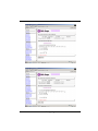
3.9.2.1
View/Edit Host Name List
To set up LUN masking for each volume, a host list should be established at first.
This is done by clicking “View/Edit Host Name List” link at bottom of “Fibre
Channel Config” page (refer to section 3.9.2). Only hosts that will be used as
include/exclude filters are necessary to be added.
To add a host to the list, first enter the WWPN (exact 16 hex digits) of the host in
the “Host WWN” text field. Optional host nick name (up to 23 ASCII characters)
can be given for descriptive purpose. Choose “Add” operation, then Confirm/
Submit to complete the add operation.
3-40
Configuring
The added host will be shown in the upper half of the Config Frame. Up to 20
hosts can be added.
To delete a host from the list, select the radio button in front of the host list.
Choose “Delete” operation, then Confirm/Submit to complete the delete operation.
Once volumes are created and the host name list is established, Volume Set
Host Filters can be specified by clicking “View/Edit Volume Set Host Filters”
link at bottom of “Fibre Channel Config” page. Volume Set Host Filters can
also be specified by clicking “Volume Set Functions” à “Volume Set Host
Filters” from the Menu Frame. Select the volume for LUN masking and then
Configuring
3-41
click the submit button.
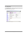
3.9.2.2 Volume Set Host Filters
Volume Set Host Filters can be specified by clicking “View/Edit Volume Set
Host Filters” link at bottom of “Fibre Channel Config” page. Volume Set Host
Filters can also be specified by clicking “Volume Set Functions” à “Volume
3-42
Configuring
Set Host Filters” from the Menu Frame.
To add a host filter entry, first select the host to be include/exclude from Host
WWN list.
Adjust Range Mask, Filter Type, Access Mode fields. Choose “Add” operation,
then Confirm/Submit to complete the add operation. The added host filter entry
will be shown in the upper half of the Config Frame. Up to 8 host filter entries can
be added.
To delete a host filter entry from the list, select the radio button in front of the host
entry.
Choose “Delete” operation, then Confirm/Submit to complete the delete operation.
Range Mark
Some times it is convenient to combine some corelated WWNs into one ID range
Configuring
3-43
as a single filter entry. This ID range is obtained by “adding” the host WWN and
the Range Mask (which are both 64-bit entities). For example, if hosts
0x210000e0_8b03dc84 and 0x210000e0_8b03dc85 have the same access control, they can be combined as a single filter entry (using either WWN as host
WWN) with Range Mask setting as 0xFFFFFFFF_FFFFFFFE. Note that under
most circumstances, the Range Mask is left as 0xFFFFFFFF_FFFFFFFF, which
means that only a single WWN is specified for that filter entry.
Filter Type
Each filter entry can be set to include or exclude certain host(s) from data access.
If a node’s WWN falls in an ID range specified as Exclude, the related Volume
Set will be “invisible” to this node and no data access is possible.
If a node’s WWN falls in an ID range specified as Include and does not fall in any
ID range specified as Exclude, this node will be allowed to access the data of the
related Volume Set.
The access mode can be specified as normal “Read/Write” or restricted “Read
Only”.
If a node’s WWN falls in none of the ranges and there is at least one Include-type
entry specified, this node is considered as Excluded; otherwise, it is considered
as Included.
Note that when no Filter Entries are specified for a Volume Set, any node can
access the Volume Set as there is no LUN masking.
Access mode
For certain applications, it is desired to limit the data access as “Read Only”
such that the data on the volume won’t be accidentally modified. This can be
done by setting the Access Mode of the Included ID range as “Read Only”. However, some Operating Systems (e.g. Linux) may ignore this “Write Protect” attribute and still issue write commands to the protected volumes.
“Data Protected” error will be resported to these write commands. It is suggested
to mount the volumes as “Read Only” for a consistent behavior, if possible.
3-44
Configuring
Configuring
3-45
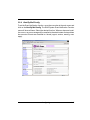
3.9.3 EtherNet Config
To set the EtherNet function, move the cursor bar to the main menu and click
on the EtherNet Config. The RAID System EtherNet Function menu will
show all items. Select the desired function.
3-46
Configuring
3.9.4 Alert By Mail Config
To set the Event Notification function, move the cursor bar to the main menu and
click on the Alert By Mail Config. The RAID System Event Notification Function
menu will show all items. Select the desired function. When an abnormal condition occurs, an error message will be emailed to the administrator that a problem
has occurred. Events are classified to 4 levels (urgent, serious, warning, message).
Configuring
3-47
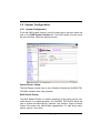
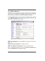
3.9.5 SNMP Configuration
The SNMP gives users independence from the proprietary network management
schemes of some manufacturers and SNMP is supported by many WAN and
LAN manufacturers enabling true LAN/ WAN management integration.
To set the SNMP function, move the cursor bar to the main menu and click
on he SNMP Configuration. The RAID System SNMP Function menu will
show all items. Select the desired function.
SNMP Trap Configurations: Type the SNMP Trap IP Address. The Port default is 162.
SNMP Community Configuration: The default is Public .
SNMP Trap Notification Configurations: Select the desired function.
After you complete the addition, Click on the Confirm The Operation and
click on the Submit button to complete the action.
3-48
Configuring
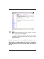
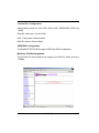
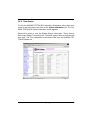
3.9.6 View Events
To view the SurfRAID TRITON 8FA controller’s information, move the mouse
cursor to the main menu and click on the System Information link. The SurfRAID TRITON 8FA Events Information screen appears.
Choose this option to view the System Events Information: Timer, Device,
Event type, Elapse Time and Errors. The RAID system does not built the real
time clock. The Time information is the relative time from the SurfRAID TRITON 8FA power on.
Configuring
3-49
3.9.7 Generate Test Events
If you want to generate test events, move the cursor bar to the main menu
and click on he Generate Test Events. Click on the Confirm The Operation, and click on the Submit button in the screen to create the hot spares.
Then click on the View Events/Mute Beeper to view the test event.
3-50
Configuring
3.9.8 Clear Events Buffer
Use this feature to clear the entire events buffer information.
3.9.9 Modify Password
To set or change the SurfRAID TRITON 8FA password, move the mouse cursor
to RAID System Function screen, and click on the Change Password link. The
Modify System Password screen appears.
Configuring
3-51
The password option allows the user to set or clear the SurfRAID TRITON
8FA’s password protection feature. Once the password has been set, the
user can only monitor and configure the SurfRAID TRITON 8FA by providing
the correct password.
The password is used to protect the SurfRAID TRITON 8FA from unauthorized entry. The controller will check the password only when entering the
Main menu from the initial screen. The SurfRAID TRITON 8FA will automatically go back to the initial screen when it does not receive any command in
ten seconds.
To disable the password, press Enter key only in both the Enter New Password
and Re-Enter New Password column. Once the user confirms the operation
and clicks the Submit button the existing password will be cleared. No password
checking will occur when entering the main menu from the starting screen.
3.9.10 Upgrade Firmware
Please reference the section 4.2 for more information.
3-52
Configuring
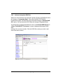
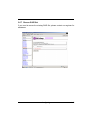
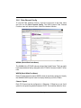
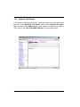
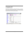
3.10 Information Menu
3.10.1 RAID Set Hierarchy
Use this feature to view the internal SurfRAID TRITON 8FA current RAID Set,
current Volume Set and physical disk configuration. Click the Volume Set number you which to View in the select column. Then you can view the Volume Set
Information and Fibre Channel Volume Set Host Filters.
Configuring
3-53
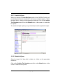
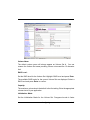
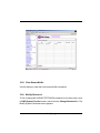
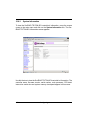
3.10.2
System Information
To view the SurfRAID TRITON 8FA controller’s information, move the mouse
cursor to the main menu and click on the System Information link. The SurfRAID TRITON 8FA Information screen appears.
Use this feature to view the SurfRAID TRITON 8FA controller’s information. The
controller name, firmware version, serial number, main processor, CPU data/
Instruction cache size and system memory size/speed appear in this screen.
3-54
Configuring
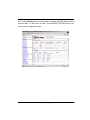
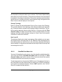
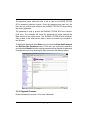
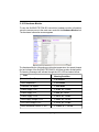
3.10.3 Hardware Monitor
To view the SurfRAID TRITON 8FA controller’s hardware monitor information,
move the mouse cursor to the main menu and click the Hardware Monitor link.
The Hardware Information screen appears.
The Hardware Monitor Information provides the temperature, fan speed (chassis
fan) and voltage of the SurfRAID TRITON 8FA. All items are also unchangeable.
The warning messages will indicate through the LCD, LED and alarm buzzer.
Item
Warning Condition
Controller Board Temperature
> 60 Celsius
HDD Temperature
> 55 Celsius
Controller Fan Speed
< 2600 RPM
Power Supply +12V
< 10.8V or > 13.2V
Power Supply +5V
< 4.5V or > 5.5V
Power Supply +3.3V
< 2.97V or > 3.63V
DDR Supply Voltage +2.5V
< 2.25V or > 2.75V
CPU Core Voltage +1.3V
< 1.17V or > 1.43V
DDR Termination Power +1.25V
< 1.125V or > 1.375V
Configuring
3-55
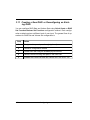
3.11 Creating a New RAID or Reconfiguring an Existing RAID
You can configure RAID Sets and Volume Sets using Quick Create or RAID
Set Functions/Volume Set Functions configuration method. Each configuration method requires a different level of user input. The general flow of operations for RAID Set and Volume Set configuration is:
Step
Action
1
Designate hot spares/pass-through (optional).
2
Choose a configuration method.
3
Create RAID Set using the available physical drives.
4
Define Volume Set using the space in the RAID Set.
5
Initialize the Volume Set and use Volume Set in the HOST OS.
3-56
Configuring
Chapter 4
Array Maintenance
This chapter describes more information about your SurfRAID TRITON 8FA. The following items are described in detail.
v
Updating Firmware
v
Hot Swap Components
Array Maintenance
4-1
4.2 Upgrading the Firmware
Upgrading Flash Firmware Programming Utility
Since the SurfRAID TRITON 8SA controller features flash firmware, it is not necessary to change the hardware flash chip in order to upgrade the RAID firmware.
The user can simply re-program the old firmware through the RS-232 port. New
releases of the firmware are available in the form of a DOS file. Firmware can be
downloaded from Partner’s web site at www.PartnersData.com.
XXXXVVV.BIN Firmware Binary (where “XXXX” refers to the model name and
“VVV” refers to the firmware version)
README.TXT It contains the history information of the firmware change. Read
this file first before upgrading the firmware.
These files must be extracted from the compressed file and copied to one directory in drive A or C.
Establishing the Connection for the RS-232
The firmware can be downloaded to the RAID subsystem controller by using an
ANSI/VT-100 compatible terminal emulation program or Remote web browser
management. You must complete the appropriate installation procedure before
proceeding with this firmware upgrade. Whichever terminal emulation program
is used must support the ZMODEM file transfer protocol.
Configuration of the internal RAID subsystem web browser-based remote RAID
management. Web browser-based RAID management can be used to update
the firmware. You must complete the appropriate installation procedure before
proceeding with this firmware upgrade.
Upgrading Firmware Through ANSI/VT-100 Terminal Emulation
4-2
Array Maintenance
Get the new version firmware for your RAID subsystem controller. For Example,
download from Partners web site onto the c:
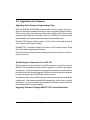
1. From the Main Menu, scroll down to “RAID System Function”
2. Choose the “Update Firmware”, The Update The RAID Firmware dialog box
appears.
3. Go to the tool bar and select Transfer. Open Send File.
Array Maintenance
4-3
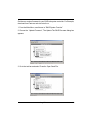
4. Select “ZMODEM modem” under Protocol. ZMODEM as the file transfer protocol of your terminal emulation software.
5. Click Browse. Look in the location where the Firmware upgrade software is
located. Select the File name:
“6160FIRM.BIN” and click open.
6. Click Send. Send the Firmware Binary to the controller
4-4
Array Maintenance
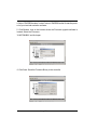
7. When the Firmware completes downloading, the confirmation screen appears.
Press Yes to start program the flash ROM.
8. When the Flash programming starts, a bar indicator will show “ Start Updating
Firmware. Please Wait:”.
Array Maintenance
4-5
9. The Firmware upgrade will take approximately thirty seconds to complete.
10. After the Firmware upgrade is complete, a bar indicator will show “ Firmware
Has Been Updated Successfully”.
NOTE:
The user has to reconfigure all of the settings after the firmware upgrade is complete, because all of the settings will default to the original
default values.
4-6
Array Maintenance
Upgrading Firmware Through Web Browser Management
Get the new version firmware for your SurfRAID TRITON 8FA controller.
1. To upgrade the SurfRAID TRITON 8FA firmware, move the cursor to Upgrade Firmware link. The Upgrade The RAID system Firmware screen appears.
2. Click Browse. Look in the location where the Firmware upgrade software is
located. Select the File name:
“6160FIRM.BIN” and click open.
3.Click the Confirm The Operation and press the Submit button.
4. The Web Browser begins to download the firmware binary to the controller
and start to update the flash ROM.
Array Maintenance
4-7
5. After the firmware upgrade is complete, a bar indicator will show “ Firmware
Has Been Updated Successfully”
4-8
Array Maintenance
4.3 Hot Swap Components
The disk array supports hot-swappable disk trays, power supply modules and
cooling fan unit. The following sections describe how to remove and install the
“Hot-Swap” parts without interrupting the data access while the disk array is on.
4.3.1 Replacing a disk
To replace a disk, perform the following steps (Refer to 2.6 Installing hard
disks)
1.
Open the tray lever by sliding the latch and wait for the drive to spin
down. The disk LED on the front panel will turn from green to red indicate the disk is powered down.
2.
Lift the lever to disengage the disk tray from the slot.
3.
Gently pull the disk tray out of the slot.
4.
Replace the HDD.
5.
Slide the tray into a slot until it clicks into place. The HDD status LED
will turn green on front panel.
6.
Press the lever in until you hear the latch click into place.
Array Maintenance
4-9
4.3.2 Replacing a Power Supply
1.
Remove the screws located at the corners of the power supply. Place
the screws in a safe place as you will need them later when you install a
new power supply.
2.
Use the handle to pull out the defective power supply.
3.
Replace it with a 300W power supply.
4.
Slide the new power supply in until it clicks into place.
5.
Replace the screws you removed in step 1.
6.
When you replace a new power supply unit, you should then push the
power supply reset switch to stop the buzzer alarm. The new power
supply unit will link with the other unit immediately and will start working
after you press the power supply reset switch, and the buzzer warning
noise will stop.
4-10
Array Maintenance
4.3.3 Replacing a Fan
1.
Unscrew the fan holder.
2.
Disconnect the fan cable that connects between the backplane and the
fan.
3.
The fans are attached to the fan holder. Remove the screws on the
corners of the defective fan. Place the screws on a safe place as you
will need them later when you install a new fan.
Note:
We recommend that you remove the fan holder from the SurfRAID
TRITON 8FA. This allows easy installation and unlimited
workspace when replacing the fan.
4.
Install a new fan using the screws you removed in step 3.
5.
Replace the fan holder.
6.
Reconnect the fan cable connections.
Array Maintenance
4-11
Appendix A
Technical Specification
RAID processor
Intel 80321 RISC 64-bit
RAID level
0, 1, 3, 5, 6, 0+1 and JBOD
Cache memory
Up to 1024MB DDR SDRAM ECC
unbuffered
No. of channels (host+disk)
2+8
Host bus interface
FC-AL (2Gb/s * 2)
Data transfer
Up to 200MB / sec
Back Plane Board
S-ATA 150
Hot swap disk bays
8
Hot swap power supply
300W * 2 w/PFC
Cooling fan
2
On-line expansion
Yes
Multiple RAID selection
Yes
Failed disk auto rebuild
Yes
Array Roaming
Yes
Bad block auto-remapping
Yes
Online RAID level migration
Yes
Audible alarm
Yes
Host Independent
Yes
Failed drive indicators
Yes
Technical Specification
A-1