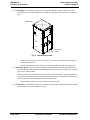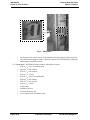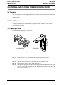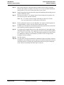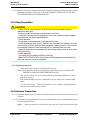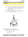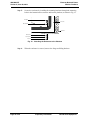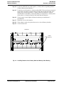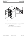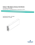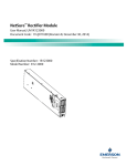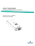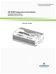
1
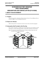
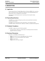
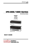
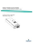
A Technical Manual from the experts
in Business-Critical Continuity™
Extended Battery Reserve Enclosure (EBRE) - F1010580
Description and Installation Manual, 460-200-055 (Version A, June 20, 2013)
This page is intentionally blank.
Emerson Network Power
Wireless Products
460-200-055
Version A, June 20, 2013
TABLE OF CONTENTS
1. ABOUT THIS DOCUMENT
1
1.1
Purpose . . . . . . . . . . . . . . . . . . . . . . . . . . . . . . . . . . . . . . . . . . . . . . . . . . . . . . . . . . . . . .
1
1.2
Reason for Reissue . . . . . . . . . . . . . . . . . . . . . . . . . . . . . . . . . . . . . . . . . . . . . . . . . . . .
1
1.3
Information Not Provided in this Practice . . . . . . . . . . . . . . . . . . . . . . . . . . . . . . . . . .
1
2. DESCRIPTION
2
2.1
Application . . . . . . . . . . . . . . . . . . . . . . . . . . . . . . . . . . . . . . . . . . . . . . . . . . . . . . . . . . .
2
2.2
Physical Specifications . . . . . . . . . . . . . . . . . . . . . . . . . . . . . . . . . . . . . . . . . . . . . . . . .
2
2.3
Standards Compliance . . . . . . . . . . . . . . . . . . . . . . . . . . . . . . . . . . . . . . . . . . . . . . . . .
2
2.4
Enclosure Dimensions . . . . . . . . . . . . . . . . . . . . . . . . . . . . . . . . . . . . . . . . . . . . . . . . . .
2
2.5
Enclosure Features . . . . . . . . . . . . . . . . . . . . . . . . . . . . . . . . . . . . . . . . . . . . . . . . . . . .
3
3. OPENING AND CLOSING THE ENCLOSURE DOORS
7
3.1
Purpose . . . . . . . . . . . . . . . . . . . . . . . . . . . . . . . . . . . . . . . . . . . . . . . . . . . . . . . . . . . . . .
7
3.2
Tools Required . . . . . . . . . . . . . . . . . . . . . . . . . . . . . . . . . . . . . . . . . . . . . . . . . . . . . . . .
7
3.3
Opening a Door . . . . . . . . . . . . . . . . . . . . . . . . . . . . . . . . . . . . . . . . . . . . . . . . . . . . . . .
7
3.4
Closing a Door . . . . . . . . . . . . . . . . . . . . . . . . . . . . . . . . . . . . . . . . . . . . . . . . . . . . . . . .
8
3.5
Resetting The EBRE Intrusion Alarm . . . . . . . . . . . . . . . . . . . . . . . . . . . . . . . . . . . . . .
8
4. INSTALLATION CONSIDERATIONS
9
4.1
Site Selection . . . . . . . . . . . . . . . . . . . . . . . . . . . . . . . . . . . . . . . . . . . . . . . . . . . . . . . . .
9
4.2
Installing a Concrete Pad . . . . . . . . . . . . . . . . . . . . . . . . . . . . . . . . . . . . . . . . . . . . . . .
9
4.3
Transportation and Storage . . . . . . . . . . . . . . . . . . . . . . . . . . . . . . . . . . . . . . . . . . . . .
11
4.4
Unpacking the Enclosure . . . . . . . . . . . . . . . . . . . . . . . . . . . . . . . . . . . . . . . . . . . . . . .
11
4.5
Lifting Preparation . . . . . . . . . . . . . . . . . . . . . . . . . . . . . . . . . . . . . . . . . . . . . . . . . . . . .
12
4.6
Enclosure Preparation . . . . . . . . . . . . . . . . . . . . . . . . . . . . . . . . . . . . . . . . . . . . . . . . . .
12
4.7
Placing the Enclosure on a Concrete Pad . . . . . . . . . . . . . . . . . . . . . . . . . . . . . . . . . .
13
4.8
Placing the Enclosure on a Platform . . . . . . . . . . . . . . . . . . . . . . . . . . . . . . . . . . . . . .
15
Outside Plant Equipment
Proprietary Information
Page i of iv
460-200-055
Version A, June 20, 2013
Emerson Network Power
Wireless Products
5. INSTALLING BATTERIES
17
5.1
17
Installation Procedure . . . . . . . . . . . . . . . . . . . . . . . . . . . . . . . . . . . . . . . . . . . . . . . . . .
6. ALARM WIRING
25
7. MAINTENANCE
25
7.1
25
Batteries . . . . . . . . . . . . . . . . . . . . . . . . . . . . . . . . . . . . . . . . . . . . . . . . . . . . . . . . . . . . .
8. REPLACEMENT PARTS
25
9. REVISION RECORD
26
Page ii of iv
Proprietary Information
Outside Plant Equipment
Emerson Network Power
Wireless Products
460-200-055
Version A, June 20, 2013
LIST OF FIGURES
Fig. 1
Extended Battery Reserve Enclosure (EBRE) . . . . . . . . . . . . . . . . . . . . . . . . . . .
1
Fig. 2
Extended Battery Reserve Enclosure Dimensions . . . . . . . . . . . . . . . . . . . . . .
3
Fig. 3
Ground Lug Location . . . . . . . . . . . . . . . . . . . . . . . . . . . . . . . . . . . . . . . . . . . . . .
4
Fig. 4
Wind Latch . . . . . . . . . . . . . . . . . . . . . . . . . . . . . . . . . . . . . . . . . . . . . . . . . . . . . . .
5
Fig. 5
Padlock / 216-type tool Lock . . . . . . . . . . . . . . . . . . . . . . . . . . . . . . . . . . . . . . . .
5
Fig. 6
Door Lock . . . . . . . . . . . . . . . . . . . . . . . . . . . . . . . . . . . . . . . . . . . . . . . . . . . . . . .
7
Fig. 7
Wind Latch Secured . . . . . . . . . . . . . . . . . . . . . . . . . . . . . . . . . . . . . . . . . . . . . . .
8
Fig. 8
Intrusion Reset Switch . . . . . . . . . . . . . . . . . . . . . . . . . . . . . . . . . . . . . . . . . . . . .
8
Fig. 9
Lifting the Enclosure . . . . . . . . . . . . . . . . . . . . . . . . . . . . . . . . . . . . . . . . . . . . . . .
13
Fig. 10
EBRE Mounting Dimensions . . . . . . . . . . . . . . . . . . . . . . . . . . . . . . . . . . . . . . . .
14
Fig. 11
Attaching the Enclosure to the Concrete Pad . . . . . . . . . . . . . . . . . . . . . . . . . .
15
Fig. 12
Attaching the Enclosure to the Platform . . . . . . . . . . . . . . . . . . . . . . . . . . . . . . .
16
Fig. 13
Typical Battery Lift . . . . . . . . . . . . . . . . . . . . . . . . . . . . . . . . . . . . . . . . . . . . . . . .
17
Fig. 14
Installing Batteries into a Battery Shelf and Battery Cable Routing . . . . . . . .
19
Fig. 15
Battery Compartment . . . . . . . . . . . . . . . . . . . . . . . . . . . . . . . . . . . . . . . . . . . . . .
20
Fig. 16
Securing the Restraint Bracket in the Horizontal Plane . . . . . . . . . . . . . . . . . .
21
Fig. 17
Connecting the Hot Cable to the Battery . . . . . . . . . . . . . . . . . . . . . . . . . . . . . .
22
Fig. 18
Routing Hot and Return Battery Cables . . . . . . . . . . . . . . . . . . . . . . . . . . . . . . .
23
Fig. 19
Battery Layout Diagram of Battery Strings +24Vdc EBRE . . . . . . . . . . . . . . . .
24
Fig. 20
10 Position Screw Down Alarm Blocks . . . . . . . . . . . . . . . . . . . . . . . . . . . . . . . .
25
Outside Plant Equipment
Proprietary Information
Page iii of iv
460-200-055
Version A, June 20, 2013
Emerson Network Power
Wireless Products
ADMONISHMENTS USED IN THIS DOCUMENT
DANGER
Warns of a hazard the reader will be exposed to that will likely result in death or
serious injury if not avoided. (ANSI, OSHA)
WARNING
Warns of a potential hazard the reader may be exposed to that could result in
death or serious injury if not avoided. This admonition is not used for situations
that pose a risk only to equipment, software, data, or service. (ANSI)
CAUTION
Warns of a potential hazard the reader may be exposed to that could result in
minor or moderate injury if not avoided. (ANSI, OSHA) This admonition is not
used for situations that pose a risk only to equipment, data, or service, even if
such use appears to be permitted in some of the applicable standards. (OSHA)
ALERT
Alerts the reader to an action that must be avoided in order to protect equipment, software, data, or service. (ISO)
ALERT
Alerts the reader to an action that must be performed in order to prevent
equipment damage, software corruption, data loss, or service interruption.
(ISO)
FIRE SAFETY
Informs the reader of fire safety information, reminders, precautions, or policies, or of the locations of fire-fighting and fire-safety equipment. (ISO)
SAFETY
Informs the reader of general safety information, reminders, precautions, or
policies not related to a particular source of hazard or to fire safety. (ISO, ANSI,
OSHA)
NOTICE
Informs the reader of general rules or policies not related to safety. (ANSI)
Page iv of iv
Proprietary Information
Outside Plant Equipment
Emerson Network Power
Wireless Products
460-200-055
Version A, June 20, 2013
EXTENDED BATTERY RESERVE
ENCLOSURE (EBRE)
DESCRIPTION AND INSTALLATION (F1010580)
1. ABOUT THIS DOCUMENT
1.1 Purpose
This practice provides a description of Emerson Network Power’s Extended Battery Reserve
Enclosure (EBRE) as well as installation instructions.
1.2 Reason for Reissue
Whenever this practice is reissued, the reason for reissue will be stated in this paragraph.
1.3 Information Not Provided in this Practice
Refer to other local practices or building codes as applicable for the correct methods, tools and
materials to be used in performing procedures not specifically described in this document.
Note: The information contained in this practice is subject to change without notice and
may not be suitable for all applications.
BRACKETS FOR
BATTERY DISCONNECT
CIRCUIT BREAKERS
CABLE
PORTS
BRACKETS FOR
BATTERY DISCONNECT
CIRCUIT BREAKERS
Fig. 1 : Extended Battery Reserve Enclosure (EBRE)
Outside Plant Equipment
Proprietary Information
Page 1 of 26
460-200-055
Version A, June 20, 2013
Emerson Network Power
Wireless Products
2. DESCRIPTION
2.1 Application
Emerson Network Power’s Extended Battery Reserve Enclosure (EBRE) (Fig. 1) provides a
stable environment for battery backup and is designed to provide supplemental DC power
backup in the event of a commercial AC power failure.
The enclosure provides thermal control to extend battery life and optimize battery
performance.
2.2 Physical Specifications
The EBRE has an off-white multistage dry powder polyester paint finish for maximum
durability and performance.
The EBRE has four lifting brackets at the top that allows it to be lifted into position.
The EBRE contains a door mounted air conditioner to maintain a constant internal temperature.
2.3 Standards Compliance
The EBRE is designed to meet the following standards:
•
Telcordia GR-487-CORE, Issue 2, March 2000, Generic Requirements for Electronic
Equipment Enclosures (Cabinets).
2.4 Enclosure Dimensions
Dimensions for the EBRE are illustrated in Fig. 2.
•
•
•
•
Page 2 of 26
Height: 79.41" (201.70 cm) over the highest part of the solar shield
Depth: 48.38" (122.89 cm) including the Heat Exchanger
Width: 36" (91.44 cm)
Weight: 960 lbs (435.45 kg) as shipped
Proprietary Information
Outside Plant Equipment
Emerson Network Power
Wireless Products
460-200-055
Version A, June 20, 2013
38.38
(97.5cm)
36.00
(91.4cm)
29.25
(74.3cm)
7.75
(19.7cm)
17.16
(43.6cm)
9.00
(22.9cm)
29.13
(74cm)
78.40
(199.1cm)
80.57
(204.6cm)
79.41
(201.7cm)
50.27
(127.7cm)
49.43
(125.5cm)
Fig. 2 : Extended Battery Reserve Enclosure Dimensions
2.5 Enclosure Features
2.5.1 Battery Backup - The EBRE houses fifteen (15) strings at 24VDC of 12Vdc 150-190Ah front
post batteries to provide backup power for existing sites. Backup time will vary depending on
the load.
The EBRE is capable of housing many battery types, including the following:
Outside Plant Equipment
BATTERY TYPE
CAPACITY
GNB
155 Ah
East Penn Mfg./DEKA
150 Ah
EnerSys/Hawker
155 Ah
Northstar
170 Ah
EnerSys
170 Ah
EastPenn
170 Ah
Proprietary Information
Page 3 of 26
460-200-055
Version A, June 20, 2013
Emerson Network Power
Wireless Products
2.5.2 Grounding - The enclosure requires one (1) ground connection using a 2 AWG wire. Two
ground points are located at the bottom rear left and right parts of the enclosure, as shown in
Fig. 3.
REAR VIEW
Ground lug
points
Fig. 3 : Ground Lug Location
•
•
A dual-hole lug that fits over 0.25" studs at 0.75" centers is included in the enclosure’s
mounting hardware kit.
The all-metal structure of the enclosure is bonded together from a ground perspective.
2.5.3 Mounting options - The enclosure is designed to be platform-mounted or pad-mounted. The
enclosure has four lifting brackets at the top that allow the enclosure to be lifted. The enclosure
may also be grate-mounted.
When the enclosure is installed on a concrete pad, a masticated rubber (reground automotive
tires) barrier pad shall be placed between the enclosure and concrete pad during installation to
prevent corrosion of the aluminum base by the concrete pad.
•
Use appropriate anchors to secure enclosure to concrete pad.
2.5.4 Cable Entry - All ancillary and DC power cables will enter and exit through cable ports located
on both sides of the main chamber. See Fig. 1.
Page 4 of 26
Proprietary Information
Outside Plant Equipment
Emerson Network Power
Wireless Products
460-200-055
Version A, June 20, 2013
2.5.5 Wind latch - A wind latch on the door of the
enclosure (Fig. 4) keeps the door secure when open.
To use the wind latch, open an enclosure door wide
enough so that the shoulder of the wind latch slides
into the hole and slot at the end of the bar. Lift up on
the wind latch to close the door.
2.5.6 Door Locks - The enclosure is equipped with
Southco type locks that secure the doors. The turn
fasteners are opened with a Telco 216-type tool
supplied with the enclosure.
Fig. 4 : Wind Latch
2.5.7 Environmental Control - The EBRE is factory
equipped with a 4000 BTU air conditioner mounted to the battery compartment door.
ALERT
The air conditioner is adjusted and tested from factory with the following temperature
settings:
HEATING
•
•
COOLING
DIAL SETTING
ON
OFF
DIAL SETTING
ON
OFF
46F
41F
46F
77F
82F
77F
The unit requires a feed of 240VAC, 15A slow blow circuit breaker. Its acoustic noise is
limited at 71dBA, measured per Telecordia standard.
A 15 Amp twist and lock power outlet is provided within the battery compartment for the
air conditioner.
Note: For details on start-up and maintenance, refer to the air conditioner manufacturing
instructions shipped with the unit.
2.5.8 Alarms - The EBRE is equipped with intrusion, high-temperature, air conditioner fail and circuit
breaker alarms:
•
Two 10 position screw down blocks are available within the battery compartment for alarm
connections, as shown in Fig. 5.
Outside Plant Equipment
Proprietary Information
Page 5 of 26
460-200-055
Version A, June 20, 2013
Emerson Network Power
Wireless Products
Fig. 5 : Alarm Block
•
•
An alarm pinout is specified in one of the schematic drawings shipped with the enclosure.
The intrusion alarm triggers whenever the door is opened. It can be disabled by pulling the
alarm plunger completely forward.
2.5.9 Loose parts - The EBRE is shipped with the following loose parts:
•
•
•
•
•
•
•
•
•
•
•
•
Page 6 of 26
Four (4) 1/2"-13x1.5" mounting bolts,
Eight (8) 1/2" flat washers,
Four (4) 1/2" lock washers,
Four (4) 1/2"-13 nuts,
Four (4) 3/8"-16x1.5" mounting bolts,
Eight (8) 3/8" flat washers,
Four (4) 3/8" lock washers,
Four (4) 3/8"-16 nuts,
a rubber mat,
installation practice,
schematic drawings, and
a user manual for air-conditioning unit.
Proprietary Information
Outside Plant Equipment
Emerson Network Power
Wireless Products
460-200-055
Version A, June 20, 2013
3. OPENING AND CLOSING THE ENCLOSURE DOORS
3.1 Purpose
This section describes the locking mechanisms on the doors of the enclosure and explains how
to open and close the doors. Refer to this section whenever instructed to open or close
enclosure doors.
3.2 Tools Required
A tamper-resistant socket wrench, which is shipped with the enclosure, will be used in
performing the procedure.
3.3 Opening a Door
Perform the following steps to open a door:
CLOSED LATCH
OPEN LATCH
Fig. 6 : Door Lock
Step 1:
Step 2:
Step 3:
Step 4:
Step 5:
If required, use a key to unlock the door according to local practices.
Insert the tamper-resistant wrench into the cup sems hex bolt.
Turn the bolt a few degrees counter clockwise to release the latch.
Lift the latch to open the door, as shown in Fig. 6.
Pull the door open wide, enough to secure the wind latch at the bottom or top of the
door. The wind latch is secured when the shoulder engages the hole and slot at the
end of the bar. (See Fig. 7.)
Outside Plant Equipment
Proprietary Information
Page 7 of 26
460-200-055
Version A, June 20, 2013
Emerson Network Power
Wireless Products
Enclosure
door
Battery
compartment
Wind latch
Fig. 7 : Wind Latch Secured
3.4 Closing a Door
Perform the following steps to close a door:
Step 1:
Step 2:
Step 3:
Step 4:
Lift the slotted bar on the wind latch to release the shoulder from the hole and slot,
as shown in Fig. 7.
Close the door.
While holding the door closed, lower the door latch into the lock bed.
Lock the door.
3.5 Resetting The EBRE Intrusion Alarm
3.5.1 Purpose - This section describes the intrusion alarm
function of the EBRE and explains how to disable
the alarm while performing routine maintenance.
•
•
•
Page 8 of 26
When the enclosure door is opened, the
intrusion switch will report an alarm.
The intrusion alarm is equipped with a pull out
switch, which when pulled, pauses alarming
functions until the switch is pressed in again.
Reset the alarm by depressing switch or by
closing the enclosure door. The intrusion
switch is shown in Fig. 8.
Proprietary Information
Fig. 8 : Intrusion Reset Switch
Outside Plant Equipment
Emerson Network Power
Wireless Products
460-200-055
Version A, June 20, 2013
4. INSTALLATION CONSIDERATIONS
4.1 Site Selection
4.1.1 The enclosure may be installed on a new or existing pad or metal platform. Obtain rights-of-way
and other permits (building permit, electrical permit, etc.), depending on local codes and
authorities, prior to installing the enclosure.
4.1.2 The mounting pad or platform must be installed (according to local practices) before the
enclosure can be installed.
4.1.3 Consider the following when deciding on the location for the rooftop site:
•
•
•
Obtain all necessary building permits and other local approvals as necessary per local
building codes.
Select locations that will provide enough space to place the mounting platform and
enclosure, and provide safe working conditions.
Select locations where there are no electrical lines that could touch the enclosure and
energize it.
4.1.4 Consider the following when deciding on the location for the concrete pad or platform:
•
•
•
•
Place the enclosure on servitudes, on dedicated (recorded) easements, or on property
owned by the company. Avoid any unrecorded easements.
Use public safety road and street rights of way only where there is enough space to place
the enclosure and provide safe working conditions. The enclosure should be easily
accessible with adequate parking to ensure safety for people and vehicles. Place the
enclosure where it will not create a visual or physical obstruction to either vehicles or
pedestrians.
Select locations that will minimize accidental or intentional vandalism. Consider the use
of protective posts when the enclosure is located near parking areas where vehicles could
back into it. Do not place the enclosure in ditches or areas subject to flooding. Do not place
the enclosure in an area where the pad is subject to vehicle loads.
If an area is subject to frost, choose a site free of heaving.
4.1.5 All enclosure grounding and ground ring must be installed prior to turn up of enclosure.
4.2 Installing a Concrete Pad
4.2.1 The enclosure may be installed on a cast-in-place or precast concrete pad. The pad should be in
place and cured before the enclosure can be installed.
4.2.2 Use concrete only for the foundation pad. Do not use substitute materials, such as reinforced
plastics, since they lack the rigidity required for enclosure placement.
4.2.3 Form preparation (follow local practices or building codes if different than the information
included in this section):
Step 1:
If the soil is not firm, compact it. For a typical installation, excavate the foundation
hole to a depth of 12 to 15 inches (30.48 to 38.1 cm).
Step 2:
Construct a level base for the pad, using a minimum of 6 inches (15.24 cm) of sand
or gravel. The pad should be level to within 1/4-inch (6.35 mm) over the entire
length and width.
Outside Plant Equipment
Proprietary Information
Page 9 of 26
460-200-055
Version A, June 20, 2013
Emerson Network Power
Wireless Products
Step 3:
Dig a trench where the cable and electrical conduit will rise into the enclosure.
Excavate the trenches to a depth of 30 inches (76.2 cm) for a standard installation,
and 60 inches (152.4 cm) for areas where there is heavy frost.
Step 4:
Install a ring ground system around the proposed foundation pad according to local
practices and safety codes.
Step 5:
Place the wire mesh (5 x 4, 4 gauge) in the form according to local practices. Be
sure the wire mesh is centered vertically.
Note: No. 3 (3/8-inch or 9 mm) or larger reinforcing rod, placed on 15-inch
(38.1 cm) centers may be used in place of wire mesh.
Step 6:
Before pouring the concrete, be sure that all the wire mesh or reinforcing bars are
set approximately 2 inches (5.08 cm) off the bottom of the form.
Step 7:
If required, use local practices to treat the area below the pad and for two feet (60.96
cm) around the perimeter against insect infestation.
Step 8:
Use a high-early strength concrete mix so the enclosure may be placed three days
following concrete pouring. Coarse aggregate used in the concrete shall be graded
from 3/4-inch (1.9 cm) to No. 4 only. The compression strength of the concrete must
be a minimum of 4000 psi as determined by ASTM C39 test of compressions
strength of concrete cylinders.
Step 9:
Pour the concrete.
Step 10: Cure the pad in a moist environment for a minimum of three days before enclosure
installation, or according to the type of concrete used, and/or local practices. Do not
install the enclosure or support any significant load before the pad is completely
cured. After the second day, the forms may be removed.
Page 10 of 26
Proprietary Information
Outside Plant Equipment
Emerson Network Power
Wireless Products
460-200-055
Version A, June 20, 2013
4.3 Transportation and Storage
WARNING
UNSECURED ENCLOSURE SECTIONS CAN TIP OVER PRESENTING A RISK OF
INJURY OR EQUIPMENT DAMAGE.
Follow all appropriate local safety and handling practices when transporting the
enclosure to a staging or installation site, or storing it.
Note: The enclosure is shipped in protective packaging on a wooden pallet. Separate
pallets MAY contain:
•
•
Batteries (ordered separately)
Mounting kit (ordered separately)
ALERT
To avoid possible damage to the enclosure, do not remove the packaging or pallet
from the packages until they are at the installation or staging site. Do not stack units
for transportation or during storage.
ALERT
If the covering on the packaging seems excessively damaged, do not accept the unit
or component from the shipper. The damaged packaging may mean the inside of the
enclosure could also be damaged, even though the outside seems fine.
4.3.1 When components are on a pallet, use lifting equipment, such as a crane or forklift, appropriately
rated for the weight of the load to raise the component and pallet.
4.3.2 Store the components upright to avoid possible damage.
4.4 Unpacking the Enclosure
CAUTION
Do not open the air conditioner door on the enclosure unless the enclosure is
secured to the pallet or the mounting surface. An unsecured enclosure is unstable
and could tip over causing injury or equipment damage.
4.4.1 Inspect the outside of the enclosure to be sure there is no shipping damage. If there is damage,
note where the damage is and how much damage there is. Follow local practices for reporting
and handling damaged goods. Do not proceed with the installation. If the enclosure appears
undamaged, go on to unpack and install the enclosure.
Outside Plant Equipment
Proprietary Information
Page 11 of 26
460-200-055
Version A, June 20, 2013
Emerson Network Power
Wireless Products
4.4.2 Carefully remove all packaging material from around the enclosure and the pallet. Dispose of the
packaging according to local practices. DO NOT REMOVE THE PALLET UNTIL THE
ENCLOSURE IS READY TO BE MOUNTED.
4.5 Lifting Preparation
CAUTION
- Follow all local safety practices while lifting the enclosure. Wear all locally
approved safety gear.
- Keep bystanders away from work operations at all times.
- All persons working with lifting equipment must wear standard safety headgear,
eye protection, and (when required) gloves.
- Crane operation
- Only properly trained operators shall operate the crane.
- Do not operate the crane until all stabilizers are extended. The stabilizers must be
in firm contact with the ground or other adequate support structure. Do not retract
or extend the stabilizers when the enclosure is suspended from the crane.
- Do not lift the enclosure over people. Do not let anyone work, stand, or pass under
a lifted enclosure.
- Forklift operation
- The forklift must be rated at 4,000 lbs (1814 kg).
- RISK OF ELECTROCUTION. Do not allow the lifting equipment or enclosure to
touch any electrical wiring or equipment
4.5.1 Equipment Required:
•
One hoist or crane capable of lifting 4,000 lbs (1814 kg).
Note: The weight of the enclosure is approximately 960 lbs (435.45 kg). DO NOT LIFT
THE ENCLOSURE WITH BATTERIES INSTALLED.
•
•
•
Four wire-rope slings, 8-ft. (2.4 m) long (minimum). Each sling should have 1,500 lb.
(680.39 kg) capacity.
Four connecting links (clevises), to attach the wire-rope slings to the enclosure lifting
plates.
A 75-ft. (22.86 m) rope, 5/8 inches in diameter, to use as a tagline. A tagline guides the
enclosure into position while it is lifted.
4.6 Enclosure Preparation
4.6.1 A schematic diagram of the AC electrical wiring is attached to the front door of the enclosure for
reference.
4.6.2 The enclosure is shipped with the 216-type tool attached to the battery compartment door to be
used for opening the door.
Step 1:
Page 12 of 26
While the enclosure is secured to the pallet, use the 216-type tool to open the door.
Proprietary Information
Outside Plant Equipment
Emerson Network Power
Wireless Products
460-200-055
Version A, June 20, 2013
CAUTION
The door with the heat exchanger / air conditioner is very heavy. Do not lean or pull
on it.
Step 2:
Step 3:
Step 4:
Step 5:
Step 6:
As the door is opened, secure the wind latch. Open the door until the shoulder slides
into the slot at the end of the bar. To release the wind latch, lift up on the lower bar.
Inspect moving parts, mounting hardware, and connectors. In case of damage,
follow local procedures for reporting damage. Close the enclosure door after
completion of inspection.
Check the packing slip and make sure all parts ordered are received.
Insert the cable sling securely through the four lifting eye brackets. Lift the cable
with the crane to take up the cable slack.
Use a 5/8" (1.59 cm) diameter rope, approximately 75-ft. (22.86 m) long as a tag
line.
MINIMUM SLING
LENGTH = 8 FEET
Fig. 9 : Lifting the Enclosure
4.7 Placing the Enclosure on a Concrete Pad
4.7.1 Tools required - The following tools are required in performing the procedure:
•
•
•
•
a 0.62" concrete drill bit for 1/2"-13 bolts,
a 0.50" concrete drill bit for 3/8"-16 bolts,
a 9/16" socket wrench, and
a 3/4" socket wrench.
Outside Plant Equipment
Proprietary Information
Page 13 of 26
460-200-055
Version A, June 20, 2013
Emerson Network Power
Wireless Products
4.7.2 Perform the following steps in securing the enclosure on a concrete pad:
Step 1:
Step 2:
Step 3:
Step 4:
Step 5:
Remove the perforated cutout from the rubber barrier pad. Use the pad as guide
when drilling holes on the concrete pad.
Drill the holes according to the recommended anchor hole size.
Clean all debris from the concrete pad where the enclosure will be placed.
Place the rubber barrier pad on the concrete pad to prevent corrosion on the
enclosure’s mounting surfaces.
Close and latch the enclosure door in preparation for lifting/placement.
ALERT
During lifting, the enclosure must be lowered so that the enclosure is level and parallel
to the platform. Place the enclosure so that it lines up with the anchor bolt locations.
Step 6:
Lift the enclosure off the truck and onto the pad. Refer to Fig. 10 when orienting the
enclosure.
4.41
(11.2cm)
26.77
(68cm)
o .500
(1.27cm)
o .500
(1.27cm)
o .625
(1.59cm)
o .625
(1.59cm)
17.94
(45.57cm)
o .500
(1.27cm)
o .500
(1.27cm)
25.89
(65.76cm)
13.60
(34.53cm)
o .625
o .625
(1.59cm)
(1.59cm)
1.28
(3.25cm)
2.30
(5.8cm)
14.85
(37.7cm)
17.00
(43.2cm)
31.41
(79.8cm)
Fig. 10 : EBRE Mounting Dimensions
Page 14 of 26
Proprietary Information
Outside Plant Equipment
Emerson Network Power
Wireless Products
Step 7:
Step 8:
460-200-055
Version A, June 20, 2013
Use a 9/16" and/or a 3/4" socket wrench when installing the mounting hardware
through the mounting holes at the bottom interior structure and into the concrete
pad. See Fig. 11 for mounting reference.
Note: Areas in seismic zones 3 and 4 are required to mount all 8 bolts (as
shown in Fig. 10). For areas in seismic zone 2 or less, either the
1/ "-13 mounting bolts or the 3/ "-16 mounting bolts can be used.
2
8
When the enclosure is secured, remove the slings and lifting brackets.
hex bolt
enclosure
flat washer
concrete pad
concrete
anchor
Fig. 11 : Attaching the Enclosure to the Concrete Pad
4.8 Placing the Enclosure on a Platform
4.8.1 Hardware and tools required - The following tools are required in performing the procedure:
•
•
•
Four mounting bolts and matching hardware suitable for platform-mounting (3/8-inch
hardware recommended), and
Four mounting bolts and matching hardware suitable for platform-mounting (1/2-inch
hardware recommended), and
9
/16" and 3/4" socket wrenches.
4.8.2 Perform the following steps in securing the enclosure on a platform:
Step 1:
Step 2:
Check to make sure the door is closed and secured.
Lift the enclosure off the truck and onto the platform mounting position.
ALERT
During lifting, the enclosure must be lowered so that the enclosure is level and parallel
to the platform. Place the enclosure so that it lines up with the anchor bolt locations.
Step 3:
Step 4:
Refer to Fig. 10 when orienting the mounting bolts and placing the enclosure.
Orient the enclosure on a platform according to local practices.
Open the enclosure door and remove the front cross braces (2), bottom battery
retainer assembly, and the bottom shelf to gain access to the mounting locations.
Outside Plant Equipment
Proprietary Information
Page 15 of 26
460-200-055
Version A, June 20, 2013
Step 5:
Emerson Network Power
Wireless Products
Secure the enclosure by installing the mounting hardware through the mounting
holes in the bottom interior structure and into the platform, as shown in Fig. 12.
hex bolt
enclosure
flat washer
platform
flat washer
lock washer
hex nut
Fig. 12 : Attaching the Enclosure to the Platform
Step 6:
Page 16 of 26
When the enclosure is secured, remove the slings and lifting brackets.
Proprietary Information
Outside Plant Equipment
Emerson Network Power
Wireless Products
460-200-055
Version A, June 20, 2013
5. INSTALLING BATTERIES
The battery compartment holds up to fifteen (15) strings at 24VDC of 12Vdc 150-190Ah front
post batteries.
•
Two batteries make one string at +24Vdc (Fig. 19).
Note: The enclosure is not shipped with batteries installed. The batteries are to be
installed in the field.
DANGER
ELECTRICAL HAZARD. Risk of fatality or serious injury and/or equipment
damage.
Exercise extreme care when handling the batteries and connecting them to the
string. Two people are recommended for lifting and placing batteries. Wear
heavy gloves and safety glasses while lifting the batteries. Handle each battery
ONLY by its lifting slot. Keep hands well away from the connector posts.
Arcing is possible during battery connection procedures. Use heavy gloves
during all procedures involving the batteries to avoid potential injury. Do not
wear rings, metallic wrist bands or bracelets when working on batteries. Do not
allow metal objects to rest on the batteries or to fall across the terminals.
Make sure both PCU ON/STANDBY switches are set to STANDBY and the
battery disconnect breakers are set to “OFF”.
5.1 Installation Procedure
Perform the following procedure to install
batteries in the EBRE:
Step 1:
Step 2:
Step 3:
Step 4:
Step 5:
If not done already, open the front door
and ensure all breakers are in the “off ”
position.
Using a Digital Multimeter (DMM),
measure the battery voltages to make
sure all batteries are in good condition.
A good battery will indicate
approximately 12.5Vdc. Per internal
battery procedures, replace any battery
measured at less than 11.0Vdc.
If necessary, remove all the connecting
hardware from the battery terminals.
Coat all battery terminals with an
anti-oxidation compound.
Locate the interconnect busbars,
covers, and lug bolts in the battery kit.
Outside Plant Equipment
Proprietary Information
Fig. 13 : Typical Battery Lift
Page 17 of 26
460-200-055
Version A, June 20, 2013
Step 6:
Step 7:
Emerson Network Power
Wireless Products
Remove battery restraint brackets from the battery shelves and set them aside for
reuse later. It is suggested that activities be performed on a shelf-by-shelf basis to
reduce potential for misplacing hardware.
Ensure cables will be in an accessible position after batteries are installed.
DANGER
BATTERY LIFTING HAZARD. Risk of serious injury if proper battery lifting
procedures are not observed. Each battery typically weighs approximately 160
lbs.
Step 8:
Install the batteries into each battery shelf of the battery compartment. See Fig. 14.
Recommended Battery Lifting Procedure: Stage the batteries for battery shelves
that are above waist high on a portable lift, such as that shown in Fig. 13 The
portable lift shall have adequate weight-lifting capacity to safely lift 600 lbs
(maximum weight of four batteries) to a height of 60 inches. Required table surface
size is 20”x20”, minimum. Lift each set of batteries until the batteries bottom edges
align with the bottom edge of the battery shelf. Ensure the lift is positioned so that
the gap between the lift’s table and the battery shelf is less than the length of the
batteries. Carefully slide each battery from the lift table to the proper position in the
battery shelf.
Step 9:
Secure batteries within the battery rack with the previously removed restraint
brackets. Some batteries may require spacer blocks if undersized for the battery
shelf.
Step 10: For each battery shelf, connect a battery interconnect busbar between the first and
second (from the left) batteries as shown in Fig. 14.
Note: When ordered, batteries are generally shipped with battery
interconnect busbars. The battery interconnect busbars are
approximately 3.25-in long.
Step 11: For each battery shelf, connect a battery interconnect busbar between the third and
fourth, and fifth and sixth (from the left) two batteries as shown in Fig. 14.
CAUTION
To prevent arcing, the positive (+) battery cables must be connected to a positive (+)
battery terminal and the negative (-) battery cable must be connected to the negative
(-) battery terminal.
Step 12: Locate two BLACK pre-wired negative (-) battery cables (originating from the
Cabinet’s Battery Return Busbar).
Step 13: Connect the negative (-) battery cable to the negative (-) battery terminal of the first
battery (from left). Connect the other negative (-) battery cable to the negative (-)
battery terminal of the third and 5th batteries. Refer to Fig. 14. for battery cable
routing. See Fig. 15 for a battery layout diagram.
Note: Ensure the battery disconnect circuit breakers located on the left and
right sides of the battery shelf are in the "OFF" position before
performing the next steps.
Page 18 of 26
Proprietary Information
Outside Plant Equipment
Emerson Network Power
Wireless Products
460-200-055
Version A, June 20, 2013
Step 14: Locate three BLACK pre-wired negative (-) battery cables (originating from the
Cabinet’s Battery Return Busbar).
Step 15: Locate the pre-wired positive (+) battery cables (BLK). These are factory connected
to the battery disconnect circuit breakers located at the left and right sides of the
battery tray. Connect one positive (+) battery cable to the positive (+) battery
terminal of the second battery. Connect the other pre wired positive (+) battery cable
to the positive (+) battery terminal of the fourth and sixth batteries.
Step 16: Using a torque wrench, tighten all battery hardware per manufacturer's
specifications.
Step 17: Install the covers on the batteries.
Step 18: If the cabinet is ready to be placed into service, close all battery breakers.
Step 19: Close the front door.
+24VDC
Battery
Retainers
Fig. 14 : Installing Batteries into a Battery Shelf and Battery Cable Routing
Outside Plant Equipment
Proprietary Information
Page 19 of 26
460-200-055
Version A, June 20, 2013
Emerson Network Power
Wireless Products
BATT
25
BATT
26
BATT
27
BATT
28
BATT
29
BATT
30
Battery Strings 10-12
BATT
19
BATT
20
BATT
21
BATT
22
BATT
23
BATT
24
Battery Strings 7-9
BATT
13
BATT
14
BATT
15
BATT
16
BATT
17
BATT
18
Battery Strings 4-6
BATT
7
BATT
8
BATT
9
BATT
10
BATT
11
BATT
12
Battery Strings 1-3
BATT
1
BATT
2
BATT
3
BATT
4
BATT
5
BATT
6
Battery Strings 13-15
Fig. 15 : Battery Compartment
Step 20: Secure batteries within the battery rack with the previously removed restraint
brackets. Battery strings shall be deployed from bottom to top.
• Each EBRE comes standard with additional battery restraint shims, shown in
Fig. 16, for installation of longer, 170A-hr battery blocks. These shims will
extend the front of the shelves by.25in.
• The two sets of fitted hardware assemblies at the bottom center of the restraint
bracket are used for securing the bracket to the horizontal plane. Do not remove
and use these for securing the battery shelf vertically.
Page 20 of 26
Proprietary Information
Outside Plant Equipment
Emerson Network Power
Wireless Products
460-200-055
Version A, June 20, 2013
Fig. 16 : Securing the Restraint Bracket in the Horizontal Plane
Step 21: Connect the supplied cables from the negative (-) battery bus bar at the top of the
battery enclosure to the negative (-) battery terminals of each battery string.
Note: Connecting the hot (24VDC) cable, however, is different from the
return (0 VDC) cable.
• The hot cable is routed forward from the top of the battery shelf and makes a
turn to the side where the circuit breaker is located. See Fig. 17.
Outside Plant Equipment
Proprietary Information
Page 21 of 26
460-200-055
Version A, June 20, 2013
Emerson Network Power
Wireless Products
Restraint
bracket
Hot
Cable
Battery
Enclosure
Circuit
Breaker
Fig. 17 : Connecting the Hot Cable to the Battery
•
•
Page 22 of 26
The return cable, on the other hand, is routed backwards on the top of the
battery, makes a turn to the side in front of the battery shelf or top restraint
bracket and goes up the busbars at the top of the enclosure.
All return cables are routed behind the upright of the enclosure. All hot cables
are routed in front of the same upright. See Fig. 18.
Proprietary Information
Outside Plant Equipment
Emerson Network Power
Wireless Products
460-200-055
Version A, June 20, 2013
Return
Cables
Hot
Cables
Fig. 18 : Routing Hot and Return Battery Cables
Step 22: Ensure all of the battery disconnect circuit breakers are in the "OFF" position before
proceeding to the next step.
Step 23: Connect the supplied cables from the battery disconnect circuit breakers to the
negative (-) battery terminals for 24V of each battery string.
Step 24: Using a torque wrench, tighten all battery hardware per manufacturer's
specifications.
Step 25: Install the provided battery inter cell connectors to form the battery strings as shown
in Fig. 19.
Step 26: Install the straps and covers on the batteries.
Step 27: Reinstall the front cross braces to the battery retainers.
Note: These braces, however, are not required in seismic zones 0, 1 and 2.
Step 28: Close the battery compartment door as described in Section 3., Opening and
Closing the Enclosure Doors.
Outside Plant Equipment
Proprietary Information
Page 23 of 26
460-200-055
Version A, June 20, 2013
Emerson Network Power
Wireless Products
POSITIVE (+) BATTERY BUS BAR
EXTERNAL CABINET
NEGATIVE (-) BATTERY BUS BAR
INTER CELL CONNECTORS
+24 Vdc
BATTERY
1
BATTERY
2
BATTERY
3
BATTERY
4
BATTERY
5
BATTERY
6
+ 24Vdc
BATTERY
DISCONNECT
CIRCUIT
BREAKERS
Fig. 19 : Battery Layout Diagram of Battery Strings +24Vdc EBRE
Page 24 of 26
Proprietary Information
Outside Plant Equipment
Emerson Network Power
Wireless Products
460-200-055
Version A, June 20, 2013
6. ALARM WIRING
6.0.1 Alarm is connected to two 10 position screw down blocks (Fig. 20) located in the battery
compartment.
Fig. 20 : 10 Position Screw Down Alarm Blocks
7. MAINTENANCE
7.1 Batteries
7.1.1 Inspect the batteries according to battery manufacturer’s instructions. Maintain records as
required by the battery manufacturer to maintain the battery warranty.
7.1.2 If a battery or batteries need replacement, refer to the instructions in Section 5., Installing
Batteries.
8. REPLACEMENT PARTS
WARNING
Contact Emerson Network Power customer service at 800-800-1280 for information
regarding replacement parts and/or accessories.
Outside Plant Equipment
Proprietary Information
Page 25 of 26
460-200-055
Version A, June 20, 2013
Emerson Network Power
Wireless Products
9. REVISION RECORD
Issue
Change
Number
(ECO)
A
RRM218960
Page 26 of 26
Description of Change
New
Proprietary Information
Outside Plant Equipment
NetPerform™ Optimization Services
At Emerson Network Power, we understand the importance of reliable equipment - its critical to both your business and your bottom line.
That is why we offer a wide array of services to meet all of your network infrastructure needs.
Customer Service (Pre-Shipment)
Email
[email protected]
Phone
1.800.800.1280 option 2
Pricing and availability [1,2], purchase orders, expediting requests
and order tracking. Ask for your company’s dedicated Customer Service
Associate.
Customer Support Center (Post-Shipment)
Email
[email protected]
Phone
1.956.661.6867
After an order has shipped, contact our Customer Support Center
with related questions, concerns or claims.
Account Management
Email
[email protected]
Phone
1.800.800.1280 option 3
Provides quotes and bid responses for custom configured [2] DC power
systems and outside plant enclosures for customers and channel partners
(Reps, VARs & Distributors).
Spare Parts
Email
[email protected]
[email protected]
Phone
1.800.800.1280 option 5
Pricing and purchase orders for spare parts, including but not limited to
breakers, cables, fuses, rectifier fans, misc. breaker and fuse panels,
enclosure fans, doors and switches, etc.
DC Power Depot Repair
Email
[email protected]
Phone
1.800.800.1280 option 6
Creates and processes RMAs for depot repair and refurbishment.
Determines repair and refurbishment lead times and pricing based on
warranties/contractual agreements. Provides repair shipping information
and status.
Technical Support
Email
[email protected]
[email protected]
Phone
1.800.800.5260
[1]
[2]
Answers technical product and system questions; determines status of
warranties and contractual agreements for repair.
Contact Account Management for custom-configurations.
Contact DC Power Spare Parts for parts and accessories.
For More Information
To learn more about service offerings from Emerson Network Power, please contact your sales representative,
call 1-800-800-1280 option 7, email [email protected] or visit EmersonNetworkPower.com/EnergySystems.
The information contained in this document is subject to change without notice and may
not be suitable for all applications. While every precaution has been taken to ensure the
accuracy and completeness of this document, Emerson Network Power, Energy Systems,
North America, Inc. assumes no responsibility and disclaims all liability for damages resulting from use of this information or for any errors or omissions. Refer to other local
practices or building codes as applicable for the correct methods, tools, and materials to
be used in performing procedures not specifically described in this document.
The products covered by this instruction manual are manufactured and/or sold by Emerson
Network Power, Energy Systems, North America, Inc. This document is the property of
Emerson Network Power, Energy Systems, North America, Inc. and contains confidential and
proprietary information owned by Emerson Network Power, Energy Systems, North
America, Inc. Any copying, use or disclosure of it without the written permission of Emerson
Network Power, Energy Systems, North America, Inc. is strictly prohibited.
Names of companies and products are trademarks or registered trademarks of the
respective companies. Any questions regarding usage of trademark names should be
directed to the original manufacturer.
EmersonNetworkPower.com/EnergySystems (North America)
EmersonNetworkPower.eu/EnergySystems (EMEA)
© Emerson Network Power Energy Systems North America 2013.
Business-Critical Continuity ™, Emerson Network Power™, the Emerson Network Power logo, Emerson® and Consider it Solved are service marks and trademarks of Emerson Electric Co.
EnergyMaster™, eSure™, NetPerform ™, NetReach™, NetSpan™, NetSure™ and NetXtend™ are trademarks of Emerson Network Power Energy Systems North America.