1
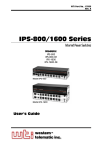
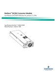
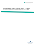
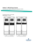
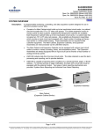
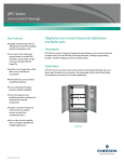
SM-TEMP Temperature Concentrator
Installation and User Manual
UM547490 (Issue AF, March 8, 2012)
SPEC. NO.: 547490
Business-Critical Continuity™, Emerson Network Power, and the Emerson Network
Power logo are trademarks and service marks of Emerson Electric Co.
®
®
Lorain and Vortex are registered trademarks of Emerson
Network Power, Energy Systems, North America, Inc.
NetSure™, NetSpan™, NetReach™, NetXtend™, and NetPerform™
are trademarks of Emerson Network Power, Energy Systems, North America, Inc.
All other trademarks are the property of their respective owners.
The products covered by this instruction manual are manufactured and/or
sold by Emerson Network Power, Energy Systems, North America, Inc.
The information contained in this document is subject to change without notice and may not be
suitable for all applications. While every precaution has been taken to ensure the accuracy and
completeness of this document, Emerson Network Power, Energy Systems, North America, Inc.
assumes no responsibility and disclaims all liability for damages resulting from use of this information
or for any errors or omissions. Refer to other local practices or building codes as applicable for the correct
methods, tools, and materials to be used in performing procedures not specifically described in this document.
This document is the property of Emerson Network Power, Energy Systems, North America, Inc.
and contains confidential and proprietary information owned by Emerson Network Power, Energy
Systems, North America, Inc. Any copying, use, or disclosure of it without the written permission
of Emerson Network Power, Energy Systems, North America, Inc. is strictly prohibited.
Copyright
©
2012, Emerson Network Power, Energy Systems, North America, Inc.
All rights reserved throughout the world.
Installation and User Instructions
Spec. No. 547490
UM547490
Issue AF, March 8, 2012
TABLE OF CONTENTS
Description ........................................................................................................................... 1
Specifications ...................................................................................................................... 2
Installation............................................................................................................................ 4
Safety Statement........................................................................................................... 4
User Selections (Switch S1) ......................................................................................... 4
Mounting ....................................................................................................................... 5
Electrical Connections .................................................................................................. 6
Initially Starting and Checking Operation .................................................................... 10
Controls and Indicators ...................................................................................................... 11
Operating Procedures ....................................................................................................... 11
Adjustments ....................................................................................................................... 11
Troubleshooting and Repair .............................................................................................. 11
Revision Record ................................................................................................................ 12
DESCRIPTION
This document provides specification, installation, and operational information for the
SM-TEMP Temperature Concentrator that is designed for use in both -48V and +24V
systems.
NetSure™ Power Systems can be operated in conjunction with one or more battery
and/or ambient temperature probes. With a battery probe installed and connected, the
power system is designed to automatically increase or decrease output voltage as battery
temperature decreases or increases, respectively. This maintains an optimum charge
voltage to the battery with respect to temperature, thereby extending battery life.
Each SM-TEMP module receives temperature inputs from up to 8 solid-state temperature
sensors (AD592B type). These are the same temperature sensors currently connected
to the temperature inputs of the SCU, SCU+, ACU, and ACU+ controllers.
The SM-TEMP module provides a 125 kbps CAN output of the temperature of all
connected sensors. There are address DIP switches to allow up to eight (8) SM-TEMP
modules to operate concurrently on the same CAN bus.
The SM-TEMP module provides an analog output of the average or the maximum (DIP
switch configurable) of the temperatures of the connected sensors. The output is a
current source providing 1 μA/K. The output is compatible with the temperature port input
of the SCU, SCU+, ACU, and ACU+ controllers. When multiple SM-TEMP modules are
used, the analog output of only one of the SM-TEMP modules is connected to the
controller’s temperature port input.
When used with an ACU+ (version 3.02 or later), in lieu of connecting the analog output
of the SM-TEMP module to an ACU+ temperature port input, the SM-TEMP module can
simply be connected at the end of the ACU+ CAN bus. Via the CAN bus, the ACU+
reads each temperature probe from each SM-TEMP module.
Page 1
This document is property of Emerson Network Power, Energy Systems, North America, Inc. and contains confidential and proprietary information owned by Emerson Network Power, Energy
Systems, North America, Inc. Any copying, use, or disclosure of it without the written permission of Emerson Network Power, Energy Systems, North America, Inc. is strictly prohibited.
UM547490
Issue AF, March 8, 2012
Installation and User Instructions
Spec. No. 547490
SPECIFICATIONS
Electrical
Input Voltage: ±18-60 volts DC
Input Current: 0.1 Amps
Input Protection: Internal 3 ampere fuse, not user replaceable. An external 1-1/3
ampere fuse should be user-provided in the ungrounded input conductor.
Environmental
Operating Ambient Temperature Range: -40°C to +70°C (-40°F to +149°F)
Temperature Measurement Range: -25°C to +105°C (-13°F to +221°F)
Storage Ambient Temperature Range: -40°C to +85°C (-40°F to +185°F)
Humidity: Capable of operating in an ambient relative humidity range of 0% to 95%,
non-condensing
Altitude: Will operate at any elevation between sea level and 10,000 ft.
Accessories
Note: This information is provided for reference. Refer to power system documentation
when ordering these accessories.
Battery Temperature Probes
Temperature probe kits are ordered separately.
3 meter – P/N 547749
10 meter – P/N 547750
Page 2
This document is property of Emerson Network Power, Energy Systems, North America, Inc. and contains confidential and proprietary information owned by Emerson Network Power, Energy
Systems, North America, Inc. Any copying, use, or disclosure of it without the written permission of Emerson Network Power, Energy Systems, North America, Inc. is strictly prohibited.
Installation and User Instructions
Spec. No. 547490
UM547490
Issue AF, March 8, 2012
Dimensions
REAR VIEW
0.34
3.18
TOP VIEW
0.23
5.31
1.71
FRONT VIEW
RIGHT SIDE VIEW
BOTTOM VIEW
Figure 1
Dimensions (in inches)
Page 3
This document is property of Emerson Network Power, Energy Systems, North America, Inc. and contains confidential and proprietary information owned by Emerson Network Power, Energy
Systems, North America, Inc. Any copying, use, or disclosure of it without the written permission of Emerson Network Power, Energy Systems, North America, Inc. is strictly prohibited.
UM547490
Issue AF, March 8, 2012
Installation and User Instructions
Spec. No. 547490
INSTALLATION
Safety Statement
DANGER: Installation of this equipment should only be performed by a qualified
installer following approved safety procedures.
This equipment is used in conjunction with batteries. Batteries are an
energy source that can produce high amounts of electrical current.
NEVER allow a metal object, such as a tool, to contact more than one
termination at a time, or to simultaneously contact a termination and a
grounded object. Even a momentary short circuit can cause an
explosion resulting in injury. To avoid such short circuits and injury:
Wear eye protection at all times.
Remove watches, bracelets, and rings.
Use only tools having insulated handles.
If insulated tools are not available, completely cover tool handles
with a minimum of three half-lapped layers of electrical tape.
Ensure that wrenches with more than one working end have only
one end exposed.
User Selections (Switch S1)
See Figure 2 for location of switch S1.
Position
Function
1
Compensation Mode
(for SM-TEMP Analog Output)
(Maximum / Average Temperature)
2
CAN Address (switch position #2
sets the most significant bit, switch
position #4 sets the least significant
bit)
3
4
Table 1
S1 Output Mode Switch Settings
Note: Up to eight (8) SM-TEMP modules may be connected together via a CAN bus.
Use switch positions 2 – 4 to give each module a unique address. See Table 2.
Switch Positions
SM-TEMP
Module #
2
3
4
1
0
0
0
2
0
0
1
3
0
1
0
4
0
1
1
5
1
0
0
6
1
0
1
7
1
1
0
8
1
1
1
Table 2
SM-Temp CAN Bus Addressing
Page 4
This document is property of Emerson Network Power, Energy Systems, North America, Inc. and contains confidential and proprietary information owned by Emerson Network Power, Energy
Systems, North America, Inc. Any copying, use, or disclosure of it without the written permission of Emerson Network Power, Energy Systems, North America, Inc. is strictly prohibited.
Installation and User Instructions
Spec. No. 547490
UM547490
Issue AF, March 8, 2012
P1-P8
TB4
TB2
S1
TB3
TB1
S1
MAX
1
1
Analog Output Cable
AVG
2
3
4
0
ADDRESS
MSB
LSB
Rear View
Figure 2
Connector Locations
Mounting
Mounting the SM-TEMP
A 6” DIN rail, P/N 116765, is included with each module.
Mounting the Battery Temperature Probes
Danger: Read the Safety Statement at the beginning of the Installation section
before mounting the probes.
Refer to power system documentation for mounting guidelines.
Page 5
This document is property of Emerson Network Power, Energy Systems, North America, Inc. and contains confidential and proprietary information owned by Emerson Network Power, Energy
Systems, North America, Inc. Any copying, use, or disclosure of it without the written permission of Emerson Network Power, Energy Systems, North America, Inc. is strictly prohibited.
UM547490
Issue AF, March 8, 2012
Installation and User Instructions
Spec. No. 547490
Electrical Connections
Refer to Figure 2 for connector locations.
General
CAN bus and analog output connections are made to TB1. TB1 provides screw
compression type terminals, which accept a wire size of 28-16 AWG. Strip 1/4"
of insulation from each lead; insert the lead in the wire cavity and tighten the
screw. Recommended torque is 2 in-lbs.
Power connections are made to terminal blocks TB2 or TB3 (the other terminal
block is available to feed this power to other SM-TEMP units or other SM
modules). TB2 and TB3 provide screw compression type terminals, which
accept a wire size of 28-16 AWG. Strip 1/4" of insulation from each lead; insert
the lead in the wire cavity and tighten the screw. Recommended torque is 2
in-lbs.
Alarm connections are made to terminal block TB4. TB4 provides screw
compression type terminals, which accept a wire size of 28-16 AWG. Strip 1/4"
of insulation from each lead; insert the lead in the wire cavity and tighten the
screw. Recommended torque is 2 in-lbs.
The SM-TEMP receives temperature information from temperature probes.
These are the same types used with the power system controllers (ACU, ACU+,
SCU, or SCU+) when the SM-TEMP is not present. The temperature probes
plug into the eight connectors on the top row on the back of the SM-TEMP (P1 –
P8). Temperature probe connections are made by means of locking-plug type
connectors.
Input Power
Note: Observe correct polarity. The + side of the power input (ground in a -48V system,
battery in a +24V system) goes to the + terminal, while the – side of the power
input goes to the – terminal. Provide an external 1-1/3A fuse in the ungrounded
input lead.
Connect power from a distribution fuse to either one of the two terminal blocks (TB2 or
TB3).
1) Connect positive (+) battery to terminal 1 of TB2 or TB3.
2) Connect negative (–) battery to terminal 2 of TB2 or TB3.
External Fail Alarm
Alarm contacts are rated for 0.5A at 125VAC, 1A at 30VDC, and 0.3A at 110VDC.
Note: Do not apply voltages higher than 42.4 volts AC (peak) or 60 volts DC.
In the event of an alarm condition, a closed loop circuit will be provided between
terminals 3 and 5 of terminal block TB4, and an open loop circuit will be provided
between terminals 1 and 3 of TB4. Refer to Figure 3 for alarm configurations.
Probes
Plug the Battery Temperature Probe(s) into connectors P1-P8 on the SM-TEMP. Probe
locations can be recorded on the label provided on the SM-TEMP.
Page 6
This document is property of Emerson Network Power, Energy Systems, North America, Inc. and contains confidential and proprietary information owned by Emerson Network Power, Energy
Systems, North America, Inc. Any copying, use, or disclosure of it without the written permission of Emerson Network Power, Energy Systems, North America, Inc. is strictly prohibited.
Installation and User Instructions
Spec. No. 547490
UM547490
Issue AF, March 8, 2012
+24V
NC
+
-
COM
-48V
FORM C
ALARM CONTACTS
NO
NC
CLOSED
= NO ALARM
+
COM
-
NO
CLOSED
= NO ALARM
CLOSED
= ALARM
CLOSED
= ALARM
ALARM USING
BATTERY CLOSURES
NC
+
COM
BATTERY
= NO ALARM
-
JUMPER
NO
NC
+
BATTERY
= ALARM
BATTERY
= NO ALARM
COM
-
NO
BATTERY
= ALARM
JUMPER
ALARM USING
GROUND CLOSURES
NC
+
GROUND
= NO ALARM
COM
-
JUMPER
NO
NC
GROUND
= ALARM
+
GROUND
= NO ALARM
COM
-
NO
GROUND
= ALARM
JUMPER
ALARM USING
RESISTIVE BATTERY CLOSURES
NC
+
COM
-
NO
NC
BATTERY
= ALARM
BATTERY
= NO ALARM
+
COM
-
NO
*
BATTERY
= NO ALARM
BATTERY
= ALARM
Resistive Value and Power Rating
per application requirements.
Figure 3
Alarm Wiring (TB4)
Page 7
This document is property of Emerson Network Power, Energy Systems, North America, Inc. and contains confidential and proprietary information owned by Emerson Network Power, Energy
Systems, North America, Inc. Any copying, use, or disclosure of it without the written permission of Emerson Network Power, Energy Systems, North America, Inc. is strictly prohibited.
UM547490
Issue AF, March 8, 2012
Installation and User Instructions
Spec. No. 547490
Interface Connection to the Power System
a) When connected to a Controller’s Temperature Port Input
The SM-TEMP module is designed to interface with the following Controllers:
ACU, ACU+, SCU, SCU+. Use cable P/N 547565 (shipped loose with each unit).
The analog output connections are made to TB1 pins 1-2. Refer to
Figure 2 and Figure 4. When multiple SM-TEMP modules are used, the
analog output of only one of the SM-TEMP modules is connected to the
controller’s temperature port input.
CAN bus connections are made to TB1 pins 3-5. See Figure 4 for
correct CAN bus wiring.
ANALOG OUTPUT CONNECTION
(when connecting the SM-TEMP analog output
to the Controller’s temperature sensor port
and not connecting into the Controller’s CAN bus)
+
TB1 1
2
H
T
3
4
CAN BUS INTERCONNECTIONS
(when connecting the SM-TEMP analog output
to the Controller’s temperature sensor port
and not connecting into the Controller’s CAN bus)
L
5
ONE (1) UNIT
H
Black Wire
Red Wire
T
L
TO CONTROLLER
(NO CAN BUS CONNECTION REQUIRED)
TWO (2) UNITS
H
T
H
L
T
L
TWISTED PAIR
L
L
H
H
THREE (3) TO EIGHT (8) UNITS
H
T
L
H
OTHER UNITS
SPLICE IN HERE
T
L
H
T
L
... OR HERE
ONE PAIR GOES
INTO UNITS, NOT
ON THE END.
ONE PAIR GOES
OUT OF UNITS, NOT
ON THE END.
DO NOT WIRE THE TEMP CONCENTRATOR THIS WAY (STAR TOPOLOGY)
H
H
H
T
L
T
L
T
L
X
H
T
L
Figure 4
SM-TEMP Connections
(when connecting the SM-TEMP analog output
to the Controller’s temperature sensor port
and not connecting into the Controller’s CAN bus)
Page 8
This document is property of Emerson Network Power, Energy Systems, North America, Inc. and contains confidential and proprietary information owned by Emerson Network Power, Energy
Systems, North America, Inc. Any copying, use, or disclosure of it without the written permission of Emerson Network Power, Energy Systems, North America, Inc. is strictly prohibited.
Installation and User Instructions
Spec. No. 547490
UM547490
Issue AF, March 8, 2012
b) When connected into the ACU+ CAN Bus
When used with an ACU+ (version 3.02 or later), in lieu of connecting the analog
output of the SM-TEMP module to an ACU+ temperature port input, the
SM-TEMP module can simply be connected at the end of the ACU+ CAN bus.
The analog output connections ARE NOT REQUIRED.
CAN bus connections are made to TB1 pins 3-5. See Figure 5 for
correct CAN bus wiring.
ANALOG OUTPUT CONNECTION NOT REQUIRED
(when connecting the SM-TEMP to the Controller’s CAN bus
and not connecting the SM-TEMP analog output
to the Controller’s temperature sensor port)
+
TB1 1
2
H
T
3
4
L
5
(NO ANALOG OUTPUT CONNECTION REQUIRED)
CAN BUS INTERCONNECTIONS
(when connecting the SM-TEMP to the Controller’s CAN bus
and not connecting the SM-TEMP analog output
to the Controller’s temperature sensor port)
ONE (1) UNIT
H
T
L
To end of power system’s CAN bus,
remove power system’s CAN bus termination plug.
TWO (2) UNITS
H
T
H
L
T
L
TWISTED PAIR
L
L
H
To end of power system’s CAN bus,
remove power system’s CAN bus termination plug.
H
THREE (3) TO EIGHT (8) UNITS
H
T
L
H
T
L
H
T
L
To end of power system’s CAN bus,
remove power system’s CAN bus termination plug.
OTHER UNITS
SPLICE IN HERE
ONE PAIR GOES
INTO UNITS, NOT
ON THE END.
... OR HERE
ONE PAIR GOES
OUT OF UNITS, NOT
ON THE END.
Figure 5
SM-TEMP Connections
(when connecting the SM-TEMP to the ACU+ CAN bus
and not connecting the SM-TEMP analog output
to the ACU+ temperature sensor port)
Page 9
This document is property of Emerson Network Power, Energy Systems, North America, Inc. and contains confidential and proprietary information owned by Emerson Network Power, Energy
Systems, North America, Inc. Any copying, use, or disclosure of it without the written permission of Emerson Network Power, Energy Systems, North America, Inc. is strictly prohibited.
UM547490
Issue AF, March 8, 2012
Installation and User Instructions
Spec. No. 547490
Initially Starting and Checking Operation
After all electrical connections have been made and verified, perform the following
procedures to start and verify SM-TEMP operation.
Initial Startup
1) With the Power System operating, verify that the STATUS LED on the SM-TEMP
is continuously illuminated GREEN.
a) If the STATUS LED does not illuminate, check for correct voltage and polarity
at terminals 1 and 2 of TB2 and / or TB3 on the SM-TEMP.
b) If the STATUS LED illuminates continuously RED, the SM-TEMP has failed.
Replace the SM-TEMP.
c) If the STATUS LED flashes red, update the temperature probe inventory by
cycling output mode switch 1 (the left-most switch) three times in rapid
succession. This should restore the STATUS LED to continuous green
illumination. Note that any alarms for open temperature probes will be
permanently lost.
d) If the STATUS LED flashes green, CAN address switches 2-4 on two
SM-TEMP units connected by single CAN bus are set to the same address.
Changing the switch settings on one of the affected SM-TEMP units should
restore the STATUS LEDs on both units to continuous green illumination.
2) Verify Power System output voltage is as required by the temperature of the
battery. Refer to the Power System documentation for details.
Checking the Fail Alarm
1) Unplug any temperature probe from the SM-TEMP.
a) Requirement: The STATUS LED flashes RED.
b) Requirement: External fail alarms activate (if connected).
2) Unplug all temperature probes from all SM-TEMP units
a) Requirement: Power System output voltage switches to a default setting of
approximately 54.48 volts DC.
3) Plug all temperature probes into the SM-TEMP.
a) Requirement: The STATUS LED illuminates GREEN.
b) Requirement: External fail alarms reset (if connected).
c) Requirement: Control of Power System output voltage is returned to
temperature probe(s) (see Power System documentation).
Page 10
This document is property of Emerson Network Power, Energy Systems, North America, Inc. and contains confidential and proprietary information owned by Emerson Network Power, Energy
Systems, North America, Inc. Any copying, use, or disclosure of it without the written permission of Emerson Network Power, Energy Systems, North America, Inc. is strictly prohibited.
Installation and User Instructions
Spec. No. 547490
UM547490
Issue AF, March 8, 2012
CONTROLS AND INDICATORS
The STATUS LED on the SM-TEMP indicates possible trouble conditions in the
SM-TEMP.
STATUS LED Does Not Illuminate: A fault in the SM-TEMP is indicated.
Check for proper input voltage (18-60 VDC) and polarity at terminals 1 (+) and 2
(–) of TB2 or TB3 on the SM-TEMP. Correct as required.
STATUS LED flashes RED: Open or short condition in probe is indicated.
Check to ensure that at least one temperature probe is connected to the
SM-TEMP.
STATUS LED illuminates GREEN: Normal operation is indicated.
Type
LED
Color
Description
Green
Module is powered and OK
Flashing Green
Module is powered, operating correctly, and has all
temperature sensors operating correctly, but two modules on
the same CAN bus have the same address.
Red
Module is powered but not operating correctly.
Flashing Red
Module is powered and operating correctly, but one or more
temperature sensors has failed or has been unplugged. To
clear the alarm from failed or unplugged temperature sensors,
toggle S1-1 three times in rapid succession.
Off
Module is not powered.
Table 3
Status Indicators
OPERATING PROCEDURES
Operation of the SM-TEMP is completely automatic, and User intervention should not be
required.
ADJUSTMENTS
Other than the initial setting of the maximum temperature / average temperature switch
and the address switches, no adjustment of the SM-TEMP is required or provided. Refer
to the Power System documentation for all Power System adjustment procedures.
TROUBLESHOOTING AND REPAIR
Note: Refer to the Power System documentation for troubleshooting possible Power
System or Battery Temperature Probe failures.
The SM-TEMP contains no user-replaceable parts. No attempt should be made to open
or repair the SM-TEMP. If repair is required, contact Emerson Network Power.
Note: See Table 3 for Status Information.
Page 11
This document is property of Emerson Network Power, Energy Systems, North America, Inc. and contains confidential and proprietary information owned by Emerson Network Power, Energy
Systems, North America, Inc. Any copying, use, or disclosure of it without the written permission of Emerson Network Power, Energy Systems, North America, Inc. is strictly prohibited.
UM547490
Issue AF, March 8, 2012
Installation and User Instructions
Spec. No. 547490
REVISION RECORD
Issue
Change
Number
(ECO)
AA
LLP214229
New
AB
LLP215397
Updated name to SM-TEMP.
AC
LLP215582
Wire colors added to Figure 3 and misc. updates.
AD
LLP215632
AE
LLP216522
Update 547490 graphics on cover page, page 1 and page 5 to reflect the new
product label P/N 548337.
Update CAN Bus Linear Topology.
AF
LLP216700
Misc. updates.
Description of Change
Page 12
This document is property of Emerson Network Power, Energy Systems, North America, Inc. and contains confidential and proprietary information owned by Emerson Network Power, Energy
Systems, North America, Inc. Any copying, use, or disclosure of it without the written permission of Emerson Network Power, Energy Systems, North America, Inc. is strictly prohibited.
NetPerform™ Optimization Services
At Emerson Network Power, we understand the importance of reliable equipment – it’s critical to both
your business and your bottom line. That is why we offer a wide array of services to meet all of your
network infrastructure needs.
Technical Support
Email
[email protected]
[email protected]
Phone
1.800.800.5260
Answers technical product and system
questions; determines status of warranties and
contractual agreements for repair.
Services - Design, Deployment & Optimization
Email
[email protected]
Phone
1.800.800.1280, option 7
FreedomCare Secure.EmersonNetworkPower.com
Provides quotes and bid responses, order
placement and scheduling for design, and
deployment and optimization services.
Download service & maintenance reports
online.
Spare Parts
Email
[email protected]
[email protected]
Phone
1.800.800.1280, option 5
Pricing and PO processing of spare parts,
including but not limited to breakers, cables,
fuses, rectifier fans, misc. breaker and fuse
panels, enclosure fans, doors & switches, etc.
DC Power Depot Repair
Email
[email protected]
Phone
1.800.800.1280, option 6
Creates and processes RMAs, determines
lead times and pricing, provides repair
shipping information and status.
DC Power Product Training
Email
Phone
[email protected] Requests for quotes, order placement and
scheduling.
1.800.800.1280, option 8
For More Information
To learn more about service offerings from Emerson Network Power, please contact your sales
representative, call 1-800-800-1280 option 7, email [email protected] or visit
www.EmersonNetworkPower.com/EnergySystems.