1
M3455AT2-CPE User’s Manual
2. Setup
3. Using the Internal Oscillator Circuit Bare Board
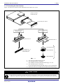
To use this product at a frequency you like, build a desired oscillator circuit on the included OSC-2 oscillator circuit bare board.
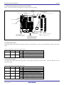
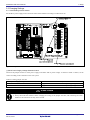
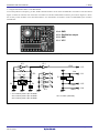
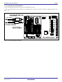
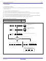
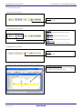
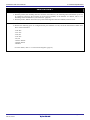
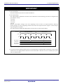
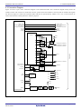
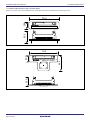
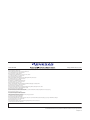
Figure 2.4 shows an external view of the OSC-2 oscillator circuit bare board and the connector pin locations. Figure 2.5 shows
the circuitry of the oscillator circuit bare board OSC-2. Use the number of oscillator circuits recommended by the oscillator
manufacturer.
J1-4: GND
J1-3: Oscillation output
J1-2: GND
J1-1: VCC
Figure 2.4 External view of the oscillator circuit board OSC-2 and its connector pin locations
IC1
11
IC1
10
9
CLK
8
J1-3
R1
*
X1, X2
*
C2
X3
*
1
2
3
4
5
6
13
12
Vcc
R2
C1
IC1
C3
J1-1
14
IC1
7
J1-2
GND
J1-4
GND
*: X1: 5.08mm pitch 2-pin oscillator
X2: 2.54mm pitch 2-pin oscillator
X3: 2.54mm pitch 3-pin oscillator
IC1: Inverter (Unbuffer)
Figure 2.5 Circuits of the oscillator circuit bare board OSC-2
R20UT0215EJ0200 Rev.2.00
Nov 01, 2010
Page 27 of 78