1
CHAPTER 7:
EMBEDDED PERIPHERALS
M. Jiménez, R. Palomera, & I. Couvertier
INTRODUCTION TO EMBEDDED SYSTEMS:
Using Microcontrollers and the MSP430
© M. Jiménez et al. 2014
Lecture
Slides
Series
INTRODUCTION TO EMBEDDED SYSTEMS: Using Microcontrollers and the MSP430
OUTLINE
Fundamental Interrupt Concepts
Interrupt Handling in the MSP430
Interrupt Software Design
Timers and Event Counters
Embedded Memory Technologies
Bus Arbitration and DMA Transfers
© 2014 by M. Jiménez, R. Palomera, & I. Couvertier
Chapter 7: 2
INTRODUCTION TO EMBEDDED SYSTEMS: Using Microcontrollers and the MSP430
• Interrupt Triggers
7.1 FUNDAMENTAL
INTERRUPT CONCEPTS
• Maskable Vs. NonMaskable
Interrupts
• Interrupt Service
Sequence
• Interrupt
Identification
• Priority Handling
© 2014 by M. Jiménez, R. Palomera, & I. Couvertier
Chapter 7: 3
INTRODUCTION TO EMBEDDED SYSTEMS: Using Microcontrollers and the MSP430
WHAT IS AN INTERRUPT?
A signal indicating the occurrence of an event that
needs immediate CPU attention
Provides for a more efficient event handling than
using polling
Less CPU cycles wasted
Advantages
Compact & Modular Code
Allow for Reduced Energy Consumption
Faster Multi-event Response Time
© 2014 by M. Jiménez, R. Palomera, & I. Couvertier
Chapter 7: 4
INTRODUCTION TO EMBEDDED SYSTEMS: Using Microcontrollers and the MSP430
INTERRUPT TRIGGERS
Hardware Triggers
Caused by external hardware components
Sensitivity Level
Edge Triggered
Rising edge
Falling edge
Level Triggered
Caused a logic level (High or Low)
Software Triggers
Caused by a software event in user’s program
CPU Exception
Internal CPU state
© 2014 by M. Jiménez, R. Palomera, & I. Couvertier
Chapter 7: 5
INTRODUCTION TO EMBEDDED SYSTEMS: Using Microcontrollers and the MSP430
MASKABLE VS. NON-MASKABLE
Maskable Interrupts
Can be blocked through a flag
Global Interrupt Flag (GIE)
Local Flags in Peripheral Interfaces
Most common type of interrupt
Disabled upon RESET
By default disabled upon entrance into an ISR
Non-maskable Interrupts (NMI)
Cannot be masked, thus are always served
Reserved for system critical events
© 2014 by M. Jiménez, R. Palomera, & I. Couvertier
Chapter 7: 6
INTRODUCTION TO EMBEDDED SYSTEMS: Using Microcontrollers and the MSP430
INTERRUPT SERVICE SEQUENCE
1. Interrupt request
2. CPU saves PC, PSW
and clears GIE
3. PC loaded with ISR
address
4. ISR executed
5. Executing IRET
restores PSW and PC
6. Interrupted program
resumes
Fig. 7.1: Sequence of events in the CPU upon accepting an interrupt request.
© 2014 by M. Jiménez, R. Palomera, & I. Couvertier
Chapter 7: 7
INTRODUCTION TO EMBEDDED SYSTEMS: Using Microcontrollers and the MSP430
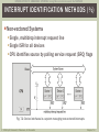
INTERRUPT IDENTIFICATION METHODS (½)
Non-vectored Systems
Single, multidrop interrupt request line
Single ISR for all devices
CPU identifies source by polling service request (SRQ) flags
Fig. 7.2: Device interfaces in a system managing non-vectored interrupts
© 2014 by M. Jiménez, R. Palomera, & I. Couvertier
Chapter 7: 8
INTRODUCTION TO EMBEDDED SYSTEMS: Using Microcontrollers and the MSP430
INTERRUPT IDENTIFICATION METHODS ( 2/2)
Vectored Interrupts
Require an Interrupt Acknowledgment (INTA) cycle
Interfaces generate an ID number (vector) upon INTA
ID number allows calculating ISR location
Auto-vectored Interrupts
Each device has a fixed vector or fixed ISR address
No INTA cycle or vector issuing required
CPU loads direct ISR address into PC to execute ISR
Method used in MSP430 MCUs
© 2014 by M. Jiménez, R. Palomera, & I. Couvertier
Chapter 7: 9
INTRODUCTION TO EMBEDDED SYSTEMS: Using Microcontrollers and the MSP430
PRIORIT Y HANDLING ( 1/3)
Interrupt Priority Management
Strategy to resolve multiple, simultaneous interrupt
requests
Priority scheme decides which one is served first
Non-vectored Systems
Polling order of SRQ flags decides priority
Vectored & Auto-vectored Systems
Hardware supported
Daisy Chain-based
Interrupt Controller-based
© 2014 by M. Jiménez, R. Palomera, & I. Couvertier
Chapter 7: 10
INTRODUCTION TO EMBEDDED SYSTEMS: Using Microcontrollers and the MSP430
PRIORIT Y HANDLING ( 2/3)
Daisy Chain-based Arbitration
Devices linked by a daisy-chain element
Simple to implement
Hardwired priorities
The closer the device to the CPU the higher the priority
Fig. 7.4: Daisy
chain logic
Fig. 7.3: Device interfaces connected in a daisy chain
© 2014 by M. Jiménez, R. Palomera, & I. Couvertier
Chapter 7: 11
INTRODUCTION TO EMBEDDED SYSTEMS: Using Microcontrollers and the MSP430
PRIORIT Y HANDLING ( 3/3)
Interrupt Controller-based Arbitration
Uses central arbiter for resolving priorities
Reduces interface overhead for vectored systems
Allows for configuring the priority scheme
Fig. 7.5: Interrupt management using a
programmable interrupt controller
© 2014 by M. Jiménez, R. Palomera, & I. Couvertier
Chapter 7: 12
INTRODUCTION TO EMBEDDED SYSTEMS: Using Microcontrollers and the MSP430
7.2 INTERRUPT
HANDLING IN THE
MSP430
© 2014 by M. Jiménez, R. Palomera, & I. Couvertier
• System Resets
• (Non)-Maskable
Interrupts
• Maskable
Interrupts
Chapter 7: 13
INTRODUCTION TO EMBEDDED SYSTEMS: Using Microcontrollers and the MSP430
MSP430 INTERRUPTS
All Internal Peripherals are Interrupt Capable
Use an internal daisy-chain scheme
Support low-power operation
Auto-vectored Approach
Fixed interrupt table
Vector addresses depend on MCU family member
Types of MSP430 Interrupts
System Resets
Non-maskable
Maskable
© 2014 by M. Jiménez, R. Palomera, & I. Couvertier
Chapter 7: 14
INTRODUCTION TO EMBEDDED SYSTEMS: Using Microcontrollers and the MSP430
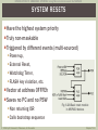
SYSTEM RESETS
Have the highest system priority
Truly non-maskable
Triggered by different events (multi-sourced)
Power-up,
External Reset,
Watchdog Timer,
FLASH key violation, etc.
Vector at address 0FFFEh
Saves no PC and no PSW
Non returning ISR
Calls bootstrap sequence
© 2014 by M. Jiménez, R. Palomera, & I. Couvertier
Fig. 6.28 Basic reset module
in MSP430 devices
Chapter 7: 15
INTRODUCTION TO EMBEDDED SYSTEMS: Using Microcontrollers and the MSP430
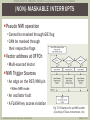
(NON)-MASKABLE INTERRUPTS
Pseudo NMI operation
Cannot be masked through GIE flag
CAN be masked through
their respective flags
Vector address at 0FFCh
Multi-sourced Vector
NMI Trigger Sources
An edge on the RST/NMI pin
When NMI mode
An oscillator fault
A FLASH key access violation
Fig. 7.6 Flowchart for an NMI handler
(Courtesy of Texas Instruments, Inc.)
© 2014 by M. Jiménez, R. Palomera, & I. Couvertier
Chapter 7: 16
INTRODUCTION TO EMBEDDED SYSTEMS: Using Microcontrollers and the MSP430
MASKABLE INTERRUPTS
Most common user type interrupt
All sources other than Reset & NMI
Masked by GIE flag
All triggers also have individual enable bits in source
peripherals
Both GIE and local must be enabled
Fixed priorities
See device interrupt table for details
External IRQ pins provided via GPIO Ports
Most devices support interrupts via P1 & P2
Single vector per port
Individual status and enable bits per pin
© 2014 by M. Jiménez, R. Palomera, & I. Couvertier
Chapter 7: 17
INTRODUCTION TO EMBEDDED SYSTEMS: Using Microcontrollers and the MSP430
• Interrupt
Programming
• Examples of
Interrupt-Based
Programs
• Multi-Source
Interrupt Handlers
7.3 INTERRUPT
SOFTWARE DESIGN
• Dealing with False
Triggers
• Interrupt Latency
and Nesting
• Interrupts and LowPower Modes
• Working with
MSP430 Low-Power
Modes
© 2014 by M. Jiménez, R. Palomera, & I. Couvertier
Chapter 7: 18
INTRODUCTION TO EMBEDDED SYSTEMS: Using Microcontrollers and the MSP430
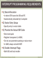
INTERRUPT PROGRAMMING REQUIREMENTS
1) Stack Allocation
Is where CPU saves the SR and PC
Automatically allocated by C-compiler
2) Vector Entry Setup
Specify entry in vector table
3) Provide the Actual ISR Code
Short and quick
Register transparent (in ASM)
Do not use parameter passing or value return
In ASM, always end with RETI
4) Enable Interrupt Flags
Both GIE and local enable
© 2014 by M. Jiménez, R. Palomera, & I. Couvertier
Chapter 7: 19
INTRODUCTION TO EMBEDDED SYSTEMS: Using Microcontrollers and the MSP430
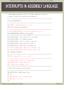
INTERRUPTS IN ASSEMBLY LANGUAGE
; Code assumes push-button in P1.3 is hardware debounced and wired to
; produce a high-to-low transition when depressed.
;--------------------------------------------------------------------------#include "msp430g2231.h"
;--------------------------------------------------------------------------RSEG CSTACK ; Stack declaration <------(1)
RSEG CODE ; Executable code begins
;--------------------------------------------------------------------------Init MOV.W #SFE(CSTACK),SP ; Initialize stack pointer <--(1)
MOV.W #WDTPW+WDTHOLD,&WDTCTL ; Stop the WDT
;--------------------------- Port1 Setup --------------------------------BIS.B #0F7h,&P1DIR ; All P1 pins but P1.3 as output
BIS.B #BIT3,&P1REN ; P1.3 Resistor enabled
BIS.B #BIT3,&P1OUT ; Set P1.3 resistor as pull-up
BIS.B #BIT3,&P1IES ; Edge sensitivity now H->L
BIC.B #BIT3,&P1IFG ; Clears any P1.3 pending IRQ
Port1IE BIS.B #BIT3,&P1IE ; Enable P1.3 interrupt <--(4)
Main BIS.W #CPUOFF+GIE,SR ; CPU off and set GIE <---(4)
NOP ; Debugger breakpoint
;--------------------------------------------------------------------------PORT1_ISR ; Begin ISR <--------------(3)
;--------------------------------------------------------------------------BIC.C #BIT3,&P1IFG ; Reset P1.3 Interrupt Flag
XOR.B #BIT2,&P1OUT ; Toggle LED in P1.2
RETI ; Return from interrupt <---(3)
;--------------------------------------------------------------------------; Reset and Interrupt Vector Allocation
;--------------------------------------------------------------------------ORG RESET_VECTOR ; MSP430 Reset Vector
DW Init ;
ORG PORT1_VECTOR ; Port.1 Interrupt Vector
DW PORT1_ISR ; <-------(2)
END
© 2014 by M. Jiménez, R. Palomera, & I. Couvertier
Chapter 7: 20
INTRODUCTION TO EMBEDDED SYSTEMS: Using Microcontrollers and the MSP430
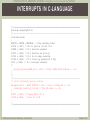
INTERRUPTS IN C-LANGUAGE
//==========================================================================
#include <msp430g2231.h>
//-------------------------------------------------------------------------void main(void)
{
WDTCTL = WDTPW + WDTHOLD; // Stop watchdog timer
P1DIR |= 0xF7; // All P1 pins as out but P1.3
P1REN |= 0x08; // P1.3 Resistor enabled
P1OUT |= 0x08; // P1.3 Resistor as pull-up
P1IES |= 0x08; // P1.3 Hi->Lo edge selected
P1IFG &= 0x08; // P1.3 Clear any pending P1.3 IRQ
P1IE |= 0x08; // P1.3 interrupt enabled
//
_ _bis_SR_register(LPM4_bits + GIE); // Enter LPM4 w/GIE enabled <---(4)
}
//
//-------------------------------------------------------------------------// Port 1 interrupt service routine
#pragma vector = PORT1_VECTOR // Port 1 vector configured <---(2)
_ _interrupt void Port_1(void) // The ISR code <----(3)
{
P1OUT ˆ= 0x04; // Toggle LED in P1.2
P1IFG &= 0̃x08; // Clear P1.3 IFG
}
//==========================================================================
© 2014 by M. Jiménez, R. Palomera, & I. Couvertier
Chapter 7: 21
INTRODUCTION TO EMBEDDED SYSTEMS: Using Microcontrollers and the MSP430
MULTI-SOURCE INTERRUPT HANDLERS
Multiple Events Served
by a Single Vector
Single ISR for all events
Specific event flags need
explicit clear
ISR code must identify
actual trigger source
Source Identification
Polling ALL interrupt request
flags
Via calculated branching
Fig. 7.7: ISR for a multi-source interrupt vector.
Identification via polling all flag sources
© 2014 by M. Jiménez, R. Palomera, & I. Couvertier
Chapter 7: 22
INTRODUCTION TO EMBEDDED SYSTEMS: Using Microcontrollers and the MSP430
USING CALCULATED BRANCHING
;===========================================================================
; Pseudo code for Multi source Interrupt Service Routine for four events
; Assumes FlagReg contains prioritized, encoded IRQ flags organized as:
; 0000 - No IRQ
0004 - Event2
0008 - Event4
; 0002 - Event 1
0006 - Event3
;--------------------------------------------------------------------------#include "headers.h"
; Header file for target MCU
...
; Preliminary declarations and code
MultiSrcISR
ADD &FlagReq,PC
; Adds Interrupt Flag Register contents to PC
JMP Exit
; Flags = 0: No interrupt
JMP Event1
; Flags = 2: Event1
JMP Event2
; Flags = 4: Event2
JMP Event3
; Flags = 6: Event3
Event4
Task 4 starts here ; Flags = 8: Event4
...
JMP Exit
; Exit ISR
Event1
Task 1 starts here ; Vector 2
...
; Task 1 starts here
JMP Exit
; Exit ISR
Event2
Task 2 starts here ; Vector 4
...
; Task 2 starts here
JMP Exit
; Exit ISR
Event2
Exit
Task 3 starts here ; Vector 4
...
; Task 3 starts here
RETI; Return
© 2014 by M. Jiménez, R. Palomera, & I. Couvertier
Calculation Methods
Look-up table-based
Via encoded flags (shown)
Chapter 7: 23
INTRODUCTION TO EMBEDDED SYSTEMS: Using Microcontrollers and the MSP430
DEALING WITH FALSE TRIGGERS
Interrupt Signals Triggered by Unwanted Events
Cause undesirable effects
Causes of False Interrupt Triggers
Power glitches
Electromagnetic Interference (EMI)
Electrostatic Discharges
Other noise manifestations
Mitigation Mechanisms
Provide dummy ISR for unused sources
Write a “False ISR Handler”
Use Watchdog Timers
Consider the use of polling
© 2014 by M. Jiménez, R. Palomera, & I. Couvertier
Chapter 7: 24
INTRODUCTION TO EMBEDDED SYSTEMS: Using Microcontrollers and the MSP430
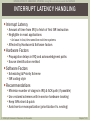
INTERRUPT LATENCY HANDLING
Interrupt Latency
Amount of time from IRQ to fetch of first ISR instruction
Negligible in most applications
An issue in fast, time sensitive real-time systems
Affected by Hardware & Software factors
Hardware Factors
Propagation delays in IRQ and acknowledgment paths
Source identification method
Software Factors
Scheduling & Priority Scheme
ISR coding style
Recommendations
Minimize number of stages in IRQ & ACK path (if possible)
Use vectored schemes with in-service hardware tracking
Keep ISRs short & quick
Avoid service monopolization (prioritization Vs. nesting)
© 2014 by M. Jiménez, R. Palomera, & I. Couvertier
Chapter 7: 25
INTRODUCTION TO EMBEDDED SYSTEMS: Using Microcontrollers and the MSP430
INTERRUPT NESTING
Achieved by re-enabling the GIE within an ISR
Use only when strictly necessary
Most applications don’t need it
Recommendations
Establish a strict prioritization
Exert SW stack depth control
Whenever possible, avoid re-entrancy
Avoid static variables – self-modification risk
Do not use self-modifying code
Re-entrant code shall only call re-entrant functions
© 2014 by M. Jiménez, R. Palomera, & I. Couvertier
Chapter 7: 26
INTRODUCTION TO EMBEDDED SYSTEMS: Using Microcontrollers and the MSP430
INTERRUPTS AND LOW-POWER MODES
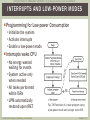
Programming for Low-power Consumption
Initialize the system
Activate interrupts
Enable a low-power mode
Interrupts wake CPU
No energy wasted
waiting for events
System active only
when needed
All tasks performed
within ISRs
LPM automatically
restored upon IRET
© 2014 by M. Jiménez, R. Palomera, & I. Couvertier
Fig. 7.8 Flowchart of a main program using
a low-power mode and a single event ISR.
Chapter 7: 27
INTRODUCTION TO EMBEDDED SYSTEMS: Using Microcontrollers and the MSP430
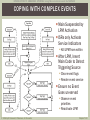
COPING WITH COMPLEX EVENTS
Main Suspended by
LPM Activation
ISRs only Activate
Service Indicators
Kill LPM from within
After LPM, Insert
Main Code to Detect
Triggering Source
Clear event flags
Render event service
Ensure no Event
Goes un-served
Observe event
priorities
Reactivate LPM
© 2014 by M. Jiménez, R. Palomera, & I. Couvertier
Chapter 7: 28
INTRODUCTION TO EMBEDDED SYSTEMS: Using Microcontrollers and the MSP430
MSP430 LOW-POWER MODES
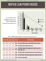
Fig. 7.9: Supply current for
MSP430F21x1 devices in their
different operating modes
(Courtesy of Texas Instruments, Inc.)
Table 7.2: MSP430 Operating Modes (Courtesy of Texas Instruments, Inc.)
© 2014 by M. Jiménez, R. Palomera, & I. Couvertier
Chapter 7: 29
INTRODUCTION TO EMBEDDED SYSTEMS: Using Microcontrollers and the MSP430
• Base Timer
Structure
7.4 TIMERS AND
EVENT COUNTERS
• Interval Timer Vs.
Event Counter
• Signature Timer
Applications
• MSP430 Timer
Support
© 2014 by M. Jiménez, R. Palomera, & I. Couvertier
Chapter 7: 30
INTRODUCTION TO EMBEDDED SYSTEMS: Using Microcontrollers and the MSP430
BASE TIMER STRUCTURE
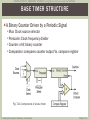
A Binary Counter Driven by a Periodic Signal
Mux: Clock source selector
Prescaler: Clock frequency divider
Counter: n-bit binary counter
Comparator: compares counter output Vs. compare register
Fig. 7.11: Components of a base timer
© 2014 by M. Jiménez, R. Palomera, & I. Couvertier
Chapter 7: 31
INTRODUCTION TO EMBEDDED SYSTEMS: Using Microcontrollers and the MSP430
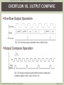
OVERFLOW VS. OUTPUT COMPARE
Overflow Output Operation
Overflow Output
Fig. 7.12 Overflow signal obtained from a 16-bit timer.
Output Compare Operation
Fig. 7.13 Output compare signal obtained when loading the
compare register with a value of three (3)
© 2014 by M. Jiménez, R. Palomera, & I. Couvertier
Chapter 7: 32
INTRODUCTION TO EMBEDDED SYSTEMS: Using Microcontrollers and the MSP430
INTERVAL TIMER VS. EVENT COUNTER
Interval Timer
Measures the time elapsed after k clock cycles
As the clock period T is known, the time interval is kT
Event Counter
Counts the occurrence of k external events
The clock is driven by the signal marking the external event
Fig. 7.14: Periodic interval of 4 clock Vs. counting four aperiodic events
© 2014 by M. Jiménez, R. Palomera, & I. Couvertier
Chapter 7: 33
INTRODUCTION TO EMBEDDED SYSTEMS: Using Microcontrollers and the MSP430
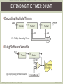
EXTENDING THE TIMER COUNT
Cascading Multiple Timers
Fig. 7.15(a): Cascading Timers
Using Software Variable
Fig. 7.15(b): Using software variable
© 2014 by M. Jiménez, R. Palomera, & I. Couvertier
Chapter 7: 34
INTRODUCTION TO EMBEDDED SYSTEMS: Using Microcontrollers and the MSP430
SIGNATURE TIMER APPLICATIONS (STA)
Watchdog Timers (WDT)
Monitor events within an expiration intervals
Real-time Clocks (RTC)
Measure time in seconds, minutes, hours and days
Baud Rate Generators (BRG)
Provide periodic signal for serial channels
Pulse-width Modulation (PWM)
Duty cycle control in periodic signals
© 2014 by M. Jiménez, R. Palomera, & I. Couvertier
Chapter 7: 35
INTRODUCTION TO EMBEDDED SYSTEMS: Using Microcontrollers and the MSP430
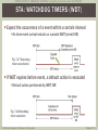
STA: WATCHDOG TIMERS (WDT)
Expect the occurrence of a event within a certain interval
On time event arrival restarts or cancels WDT (event ISR)
Fig. 7.17 Watchdog
timer cancellation
If WDT expires before event, a default action is executed
Default action performed by WDT ISR
Fig. 7.16 Watchdog
timer expiration
© 2014 by M. Jiménez, R. Palomera, & I. Couvertier
Chapter 7: 36
INTRODUCTION TO EMBEDDED SYSTEMS: Using Microcontrollers and the MSP430
MSP430 WATCHDOG TIMER
Basic Features
16-bit timer
Can be used as WDT or as interval timer
Sourced from ACLK or SMCLK
Password protected
All accesses must have key 05Ah in upper byte
Violations cause a PUC
WDT Operation
Default mode upon Reset
User programs either use it for reliable SW control or cancel it upon reset
Restarts system upon a software problem
Max count: 32768 cycles
Interval Timer Operation
Configured via WDTTMSEL
Provides programmable periodic interrupts
© 2014 by M. Jiménez, R. Palomera, & I. Couvertier
Chapter 7: 37
INTRODUCTION TO EMBEDDED SYSTEMS: Using Microcontrollers and the MSP430
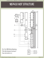
MSP430 WDT STRUCTURE
Fig. 7.21: MSP430x2xx Watchdog
Timer block diagram (Courtesy of
Texas Instruments, Inc.)
© 2014 by M. Jiménez, R. Palomera, & I. Couvertier
Chapter 7: 38
INTRODUCTION TO EMBEDDED SYSTEMS: Using Microcontrollers and the MSP430
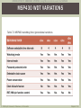
MSP430 WDT VARIATIONS
Table 7.3: MSP430 watchdog timer generational variations
© 2014 by M. Jiménez, R. Palomera, & I. Couvertier
Chapter 7: 39
INTRODUCTION TO EMBEDDED SYSTEMS: Using Microcontrollers and the MSP430
STA: REAL-TIME CLOCKS (RTC)
Timer to Measure Seconds, Minutes, Hors, Etc.
Includes registers for each time unit
Chronometer Type
Measure fractions of a second
Calendar type (RTCC)
Measure days, weeks, months, and years
Clock Source Dependence
Accuracy depends on CLK frequency
Sweet frequencies preferred (32768KHz)
© 2014 by M. Jiménez, R. Palomera, & I. Couvertier
Chapter 7: 40
INTRODUCTION TO EMBEDDED SYSTEMS: Using Microcontrollers and the MSP430
MSP430 REAL-TIME CLOCK MODULE
Basic Features
32-bit timer with selectable clock sources
Can be used as calendar or counter
Full featured register set
Seconds, Minutes, Hours, Day of the week, day of the month, & year
Hex or BCD output format
Calendar Mode
Features full set of registers
Leap year capable from 1901 to 2099
Timer 1 (x4xx) used as pre-divider of ACLK source
Counter Mode
Four 8-bit counters provide a 32-bit timer operation
Software-defined functionality
© 2014 by M. Jiménez, R. Palomera, & I. Couvertier
Chapter 7: 41
INTRODUCTION TO EMBEDDED SYSTEMS: Using Microcontrollers and the MSP430
MSP430 RTC MODULE STRUCTURE
Fig. 7.18: MSP430x4xx Real-time
Clock Module block diagram
(Courtesy of Texas Instruments, Inc.)
© 2014 by M. Jiménez, R. Palomera, & I. Couvertier
Chapter 7: 42
INTRODUCTION TO EMBEDDED SYSTEMS: Using Microcontrollers and the MSP430
STA: BAUD RATE GENERATION
Timers Can Provide Clock Base for Baud Rate
Directly impacts bit time
Main baud clock for simple UART modules
Dedicated Timer Channel Usage
Baud Rate Accuracy Dependence
Sweet frequencies preferred
f clk
baud rate
PS TopCount
PS = Prescaler Value
TopCount = Compare Value
fclk = Clock Frequency
Avoid fclk values producing large fractional quotients
© 2014 by M. Jiménez, R. Palomera, & I. Couvertier
Chapter 7: 43
INTRODUCTION TO EMBEDDED SYSTEMS: Using Microcontrollers and the MSP430
STA: PULSE WIDTH MODULATION (PWM)
Timer Application for Controlling
Duty Cycle and
Frequency of a Periodic Signal
Applications
Data Encoding
Motor Control
Voltage Regulation
Tone Generation
Power & Energy Delivery Control
Control Parameters
Top Count (Duty Cycle)
Counter Timer (Resolution)
Frequency (System Response Time)
© 2014 by M. Jiménez, R. Palomera, & I. Couvertier
Chapter 7: 44
INTRODUCTION TO EMBEDDED SYSTEMS: Using Microcontrollers and the MSP430
PWM STRUCTURE & WAVEFORMS
Fig. 7.19: Pulse-width modulation
module: (a) hardware structure,
(b) signal output
© 2014 by M. Jiménez, R. Palomera, & I. Couvertier
Chapter 7: 45
INTRODUCTION TO EMBEDDED SYSTEMS: Using Microcontrollers and the MSP430
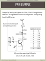
PWM EXAMPLE
Example 7.9: Controlling the brightness of a 240lm, 720mA LED using 8 different
PWM levels. LED brightness is a function of the average current intensity passing
through the LED junction.
Fig. 7.20: LED connection diagram
and required duty cycle values
High count values assuming an 8-bit counter:
0, 32, 64, 96, 128, 160, 192, or 224
© 2014 by M. Jiménez, R. Palomera, & I. Couvertier
Chapter 7: 46
INTRODUCTION TO EMBEDDED SYSTEMS: Using Microcontrollers and the MSP430
MSP430 TIMER_A
16-bit
Timer/Counter
3-bit Prescaler
3 Capture/Compare
Registers
Four Modes
Stop, Up, Continuous,
Up/Down
Selectable Clock
Source
Configurable
Outputs
PWM Capable
Fig. 7.22: MSP430 Timer_A block diagram
(Courtesy of Texas Instruments, Inc.)
© 2014 by M. Jiménez, R. Palomera, & I. Couvertier
Chapter 7: 47
INTRODUCTION TO EMBEDDED SYSTEMS: Using Microcontrollers and the MSP430
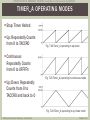
TIMER_A OPERATING MODES
Stop: Timer Halted
Up: Repeatedly Counts
from 0 to TACCR0
Fig. 7.24 Timer_A operating in up mode
Continuous:
Repeatedly Counts
from 0 to 0FFFFh
Up/Down: Repeatedly
Counts from 0 to
TACCRO and back to 0
Fig. 7.25 Timer_A operating in continuous mode
Fig. 7.26 Timer_A operating in up/down mode
© 2014 by M. Jiménez, R. Palomera, & I. Couvertier
Chapter 7: 48
INTRODUCTION TO EMBEDDED SYSTEMS: Using Microcontrollers and the MSP430
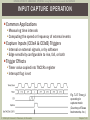
INPUT CAPTURE OPERATION
Common Applications
Measuring time intervals
Computing the speed or frequency of external events
Capture Inputs (CCIxA & CCIxB) Triggers
Internal or external signals, or by software
Edge sensitivity configurable to rise, fall, or both
Trigger Effects
Timer value copied into TACCRx register
Interrupt flag is set
Fig. 7.27: Timer_A
operating in
capture mode
(Courtesy of Texas
Instruments, Inc.)
© 2014 by M. Jiménez, R. Palomera, & I. Couvertier
Chapter 7: 49
INTRODUCTION TO EMBEDDED SYSTEMS: Using Microcontrollers and the MSP430
OUTPUT COMPARE OPERATION
Common Applications
Generating PWM signals
Producing interrupts at specific time intervals
Events Triggered by TAR Reaching TACCRx Value
Interrupt flag CCIFG is set and EQUx = 1
EQUx affects the output according to the output mode
The input signal CCI is latched into SCCI
Output Unit (OU)
Makes timed signal available on I/O pins
One output unit per capture/compare block
Eight configurable output modes per output
© 2014 by M. Jiménez, R. Palomera, & I. Couvertier
Chapter 7: 50
INTRODUCTION TO EMBEDDED SYSTEMS: Using Microcontrollers and the MSP430
OUTPUT UNIT MODES
Table 7.5: Output unit modes (Courtesy of Texas Instruments, Inc.)
© 2014 by M. Jiménez, R. Palomera, & I. Couvertier
Chapter 7: 51
INTRODUCTION TO EMBEDDED SYSTEMS: Using Microcontrollers and the MSP430
OUTPUT WAVEFORM EXAMPLES
Timer_A in UP Mode
Timer_A in Up/Down Mode
Figure 7.28: Output unit waveforms (Courtesy of Texas Instruments, Inc.)
© 2014 by M. Jiménez, R. Palomera, & I. Couvertier
Chapter 7: 52
INTRODUCTION TO EMBEDDED SYSTEMS: Using Microcontrollers and the MSP430
PWM CODING EXAMPLE
Example 7.13: This program generates one PWM output on P1.2 using Timer_A configured for
up mode. The value in CCR0, 512-1, defines the PWM period and the value in CCR1 the PWM
duty cycles. A 75% duty cycle is on P1.2. ACLK = n/a, SMCLK = MCLK = T ACLK = def ault DCO
;==========================================================================
;MSP430G2xx1 Demo - Timer_A, PWM TA1, Up Mode, DCO SMCLK
;By D. Dang - (c) 2010 Texas Instruments, Inc.
;-------------------------------------------------------------------------#include <msp430.h>
;-------------------------------------------------------------------------ORG 0F800h ; Program Reset
;-------------------------------------------------------------------------RESET
mov.w #0280h,SP
; Initialize stack pointer
StopWDT
mov.w #WDTPW+WDTHOLD,&WDTCTL
; Stop WDT
SetupP1
bis.b #00Ch,&P1DIR
; P1.2 and P1.3 output
bis.b #00Ch,&P1SEL
; P1.2 and P1.3 TA1/2 options
SetupC0
mov.w #512-1,&CCR0
; PWM Period
SetupC1
mov.w #OUTMOD_7,&CCTL1
; CCR1 reset/set
mov.w #384,&CCR1
; CCR1 PWM Duty Cycle
SetupTA
mov.w #TASSEL_2+MC_1,&TACTL
; SMCLK, up mode
;
Mainloop
bis.w #CPUOFF,SR
; CPU off
nop
; Required only for debugger
;-------------------------------------------------------------------------; Interrupt Vectors
;-------------------------------------------------------------------------ORG 0FFFEh
; MSP430 RESET Vector
DW RESET
;
END
© 2014 by M. Jiménez, R. Palomera, & I. Couvertier
Chapter 7: 53
INTRODUCTION TO EMBEDDED SYSTEMS: Using Microcontrollers and the MSP430
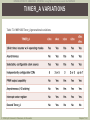
TIMER_A VARIATIONS
Table 7.3: MSP430 Timer_A generational variations
© 2014 by M. Jiménez, R. Palomera, & I. Couvertier
Chapter 7: 54
INTRODUCTION TO EMBEDDED SYSTEMS: Using Microcontrollers and the MSP430
OTHER MSP430 TIMER RESOURCES
Basic Timer
Available in legacy x3xx and x4xx devices
Two independent, cascadable, interrupt-driven 8-bit timers
Timer_B
Same as Timer_A with seven CCRs
Watchdog Timer +
Similar to WDT discussed earlier
Real-time Clock
Available in x4xx, x5xx, and x6xx devices
32-bit counter with calendar function
Seconds, minutes, hours, DOW, DOM, month, year (w/leap)
Selectable BCD output
© 2014 by M. Jiménez, R. Palomera, & I. Couvertier
Chapter 7: 55
INTRODUCTION TO EMBEDDED SYSTEMS: Using Microcontrollers and the MSP430
7. 5 EMBEDDED
MEMORY
TECHNOLOGIES
© 2014 by M. Jiménez, R. Palomera, & I. Couvertier
• A Classification of
Memory
Technologies
• Flash Memory:
General Principles
• MSP430 Flash
Memory and
Controller
Chapter 7: 56
INTRODUCTION TO EMBEDDED SYSTEMS: Using Microcontrollers and the MSP430
EMBEDDED MEMORY CHARACTERISTICS
Control-dominated
Applications
High-performance
Systems
Program Memory
Program Memory
Non-volatile
Small to moderate amount
Data Memory
Run-time Variables
Volatile OK
Small amount
System Parameters
Non-volatile
Very small
Data Storage (rarely used)
Large
Non-volatile
© 2014 by M. Jiménez, R. Palomera, & I. Couvertier
Large amount
Non-volatile
Re-writable for firmware
upgrade
Data memory
Large amount
Media processing
applications
Volatile OK
Data Storage
Very Large
Non-volatile
Chapter 7: 57
INTRODUCTION TO EMBEDDED SYSTEMS: Using Microcontrollers and the MSP430
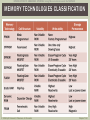
MEMORY TECHNOLOGIES CLASSIFICATION
© 2014 by M. Jiménez, R. Palomera, & I. Couvertier
Chapter 7: 58
INTRODUCTION TO EMBEDDED SYSTEMS: Using Microcontrollers and the MSP430
FLASH MEMORY STRUCTURE
Based on Floating-gate MOSFET (FGMOS)
Reads like a ROM cell
Charge trapping/removal required for modification
Finite number of erase/re-program cycles
Content Modification
Erased by pages
Reprogram cycle
Fig. 7.30: Floating Gate MOSFET(FGMOS) (a) Basic structure; (b) Erasing process;
(c) Programming; (d) Symbol
© 2014 by M. Jiménez, R. Palomera, & I. Couvertier
Chapter 7: 59
INTRODUCTION TO EMBEDDED SYSTEMS: Using Microcontrollers and the MSP430
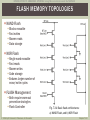
FLASH MEMORY TOPOLOGIES
NAND Flash
Blocks erasable
Fast writes
Slower reads
Data storage
NOR Flash
Single word erasable
Fast reads
Slower writes
Code storage
Endures larger number of
erase/write cycles
FLASH Management
Both require worn-out
prevention strategies
Flash Controller
© 2014 by M. Jiménez, R. Palomera, & I. Couvertier
Fig. 7.31: Basic flash architectures:
a) NAND Flash, and b) NOR Flash
Chapter 7: 60
INTRODUCTION TO EMBEDDED SYSTEMS: Using Microcontrollers and the MSP430
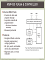
MSP430 FLASH & CONTROLLER
Internal MCU Flash
Provides for data and
program storage
In-system erasable &
programmable
No external hardware
necessary
Password protected
Features
Integrated Flash controller
Internal programming
voltage generator
Bit, byte, word, and doubleword (x5xx) addressable
Segment, bank, or mass
erasable
© 2014 by M. Jiménez, R. Palomera, & I. Couvertier
Fig. 7.32a: Flash memory block diagram
(Courtesy of Texas Instruments, Inc.)
Chapter 7: 61
INTRODUCTION TO EMBEDDED SYSTEMS: Using Microcontrollers and the MSP430
FLASH MEMORY ORGANIZATION
Information Section
Intended for non-volatile data
Can contain data or code
Composed of multiple segments
Segment number and size varies with device & MCU family
Main Section
Intended for user programs
Can contain code or data
Device dependent partitioning
Two or more segments
May have banks and/or blocks depending on device & family
Bootstrap Loader
Present only in x5xx/x6xx devices
Contains 4 segments (A … D)
Intended for booting code
Can contain code or data
© 2014 by M. Jiménez, R. Palomera, & I. Couvertier
Chapter 7: 62
INTRODUCTION TO EMBEDDED SYSTEMS: Using Microcontrollers and the MSP430
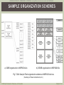
SAMPLE ORGANIZATION SCHEMES
a) 32KB organization in MSP430x2xx
b) 256KB organization in MSP430x5xx
Fig. 7.32b: Sample Flash organization schemes in MSP430 devices
(Courtesy of Texas Instruments, Inc.)
© 2014 by M. Jiménez, R. Palomera, & I. Couvertier
Chapter 7: 63
INTRODUCTION TO EMBEDDED SYSTEMS: Using Microcontrollers and the MSP430
FLASH CONTROL REGISTERS
Four Control
Registers
All are 16-bit wide
Device dependent
All are Password
Protected
Key = 0A5h
Loaded as high
byte control word
Flash Memory
Security Violation
Caused by a Flash
access w/o key
Causes a PUC
(system reset)
© 2014 by M. Jiménez, R. Palomera, & I. Couvertier
Fig. 7.32 MSP430 low bytes of flash memory control registers
Chapter 7: 64
INTRODUCTION TO EMBEDDED SYSTEMS: Using Microcontrollers and the MSP430
FLASH PROGRAMMING
© 2014 by M. Jiménez, R. Palomera, & I. Couvertier
Chapter 7: 65
INTRODUCTION TO EMBEDDED SYSTEMS: Using Microcontrollers and the MSP430
FLASH MEMORY OPERATION
Read Mode: Default Upon Reset
Contents modification requires Erase-Write sequence
Erasing the Flash
Minimum erase is one segment
Segments, Banks, and the whole Flash (mass) can be erased
Can be done from several places
From another flash segment, from RAM, or from BSL
Writing the Flash
Can write bytes, words, long words (x5xx), segments, or blocks
Write access achieved by several means
From another flash segment, from RAM, or form BSL
Programming the Flash
Programs can be downloaded via JTAG, BSL, or Custom Solution
Operation Sequence
Specific details change with device capacities and family
Refer to specific device’s User’s Manual & Data Sheet for details
© 2014 by M. Jiménez, R. Palomera, & I. Couvertier
Chapter 7: 66
INTRODUCTION TO EMBEDDED SYSTEMS: Using Microcontrollers and the MSP430
BUS ARBITRATION &
DMA TRANSFERS
© 2014 by M. Jiménez, R. Palomera, & I. Couvertier
• Fundamental
Concepts in Bus
Arbitration
• Direct Memory
Access Controllers
• MSP430 DMA
Support
Chapter 7: 67
INTRODUCTION TO EMBEDDED SYSTEMS: Using Microcontrollers and the MSP430
BUS ARBITRATION CONCEPTS
Bus Master
Device controlling Address,
Data, & Control buses
CPU is default bus master
Bus Arbitration Process
Allows bus master capable
devices request and gain
control of system buses
Sample bus master capable
devices (other than CPU)
DMA controllers
GPUs
Math Co-processors
Other CPUs (multiprocessors)
© 2014 by M. Jiménez, R. Palomera, & I. Couvertier
Fig. 3.1 General architecture
of a microcomputer system
Chapter 7: 68
INTRODUCTION TO EMBEDDED SYSTEMS: Using Microcontrollers and the MSP430
SIMPLE BUS ARBITRATION PROTOCOL
Basic Steps
1. Request
2. Grant
3. Release
Fig. 7.33: Simple scenario for a bus arbitration transaction
Fig. 7.34 Timing
of a bus request
and granting
process
© 2014 by M. Jiménez, R. Palomera, & I. Couvertier
Chapter 7: 69
INTRODUCTION TO EMBEDDED SYSTEMS: Using Microcontrollers and the MSP430
PRIORIT Y ARBITRATION
When is it Needed?
When multiple potential masters place bus requests
How is it Handled?
Assigning priorities to bus requests
Similar to Interrupt Priority Handling
Priority Management Schemes
Serial Arbitration
Daisy chain schemes
Central Arbitration
Dedicated arbiter
Configurable controller
© 2014 by M. Jiménez, R. Palomera, & I. Couvertier
Chapter 7: 70
INTRODUCTION TO EMBEDDED SYSTEMS: Using Microcontrollers and the MSP430
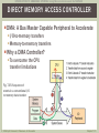
DIRECT MEMORY ACCESS CONTROLLER
DMA: A Bus Master Capable Peripheral to Accelerate
I/O-to-memory transfers
Memory-to-memory transfers
Why a DMA Controller?
To overcome the CPU
transfer limitations
Fig. 7.35: Sequence of
events in a conventional I/O
to memory data transfer
© 2014 by M. Jiménez, R. Palomera, & I. Couvertier
Chapter 7: 71
INTRODUCTION TO EMBEDDED SYSTEMS: Using Microcontrollers and the MSP430
INSERTING A DMA INTO THE SYSTEM
Connected as a Bus Master Capable Peripheral
Accessed as a regular peripheral to be configured
Replaces the CPU as bus master
After a successful bus arbitration transaction
Enables Direct Transfers to/from Memory without
CPU Intervention
Fig. 7.36: Connecting a DMA
controller to an MPU system
and I/O device
© 2014 by M. Jiménez, R. Palomera, & I. Couvertier
Chapter 7: 72
INTRODUCTION TO EMBEDDED SYSTEMS: Using Microcontrollers and the MSP430
DMA CONTROLLER STRUCTURE (1/2)
Fig. 7.37: Minimal structure of a one-channel DMA controller
© 2014 by M. Jiménez, R. Palomera, & I. Couvertier
Chapter 7: 73
INTRODUCTION TO EMBEDDED SYSTEMS: Using Microcontrollers and the MSP430
DMA CONTROLLER STRUCTURE (2/2)
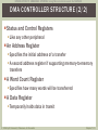
Status and Control Registers
Like any other peripheral
An Address Register
Specifies the initial address of a transfer
A second address register if supporting memory-to-memory
transfers
A Word Count Register
Specifies how many words will be transferred
A Data Register
Temporarily holds data in transit
© 2014 by M. Jiménez, R. Palomera, & I. Couvertier
Chapter 7: 74
INTRODUCTION TO EMBEDDED SYSTEMS: Using Microcontrollers and the MSP430
DMA TRANSFER MODES
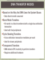
Based on the Way the DMA Uses the System Buses
Data block transfer assumed
Burst Mode Transfers
All words in a block transferred with a single bus arbitration
transaction
Used with fast peripherals
Cycle Stealing Transfers
A bus arbitration transaction mediates per word
Used for slower peripherals
Transparent Transfers
DMA detects CPU inactivity to perform transfers
Requires additional hardware
© 2014 by M. Jiménez, R. Palomera, & I. Couvertier
Chapter 7: 75
INTRODUCTION TO EMBEDDED SYSTEMS: Using Microcontrollers and the MSP430
DMA TRANSFER T YPES
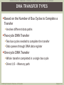
Based on the Number of Bus Cycles to Complete a
Transfer
Involves different data paths
Two-cycle DMA Transfer
Two bus cycles needed to complete the transfer
Data passes through DMA data register
One-cycle DMA Transfer
Whole transfer completed in a single bus cycle
Direct I/O – Memory path
© 2014 by M. Jiménez, R. Palomera, & I. Couvertier
Chapter 7: 76
INTRODUCTION TO EMBEDDED SYSTEMS: Using Microcontrollers and the MSP430
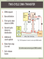
TWO-CYCLE DMA TRANSFER
1. DMA request
2. Bus arbitration
3. First cycle: store
datum in DMA
4. Second cycle:
datum to
destination
5. Address &
count update
6. Redo from step
3 or exit
Fig. 7.38: Sequence of events in a two-cycle DMA transfer
By far the most common type of DMA transfers
7. Exit: release
buses
© 2014 by M. Jiménez, R. Palomera, & I. Couvertier
Chapter 7: 77
INTRODUCTION TO EMBEDDED SYSTEMS: Using Microcontrollers and the MSP430
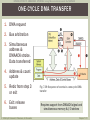
ONE-CYCLE DMA TRANSFER
1. DMA request
2. Bus arbitration
3. Simultaneous
address &
DMAACK strobe.
Data transferred
4. Address & count
update
5. Redo from step 3
or exit
6. Exit: release
buses
© 2014 by M. Jiménez, R. Palomera, & I. Couvertier
Fig. 7.39: Sequence of events in a one-cycle DMA
transfer
Requires support from DMAACK signal and
simultaneous memory & I/O strobes
Chapter 7: 78
INTRODUCTION TO EMBEDDED SYSTEMS: Using Microcontrollers and the MSP430
DMA PROGRAMMING HINTS
Designer Establishes DMA Usage
Establishes which peripherals
Decides how the DMA will be used
User Program Configures DMA
Provide starting address and block size
Decides transfer type and mode
Application Dictates the Rules
Based on speed transfer needs and peripheral type
© 2014 by M. Jiménez, R. Palomera, & I. Couvertier
Chapter 7: 79
INTRODUCTION TO EMBEDDED SYSTEMS: Using Microcontrollers and the MSP430
MSP430 DMA SUPPORT
Provided by many MSP430 Models
Features
Several independent transfer channels
Configurable DMA channel priorities
Supports only two-cycle transfers
byte-to-byte
word-to-word, and
mixed byte/word transfers
Maximum block sizes up to 65,535 bytes or words
Configurable transfer trigger selections
Selectable edge or level-triggered DMA transfer requests
Support for single, block, or burst-block transfer modes
© 2014 by M. Jiménez, R. Palomera, & I. Couvertier
Chapter 7: 80
INTRODUCTION TO EMBEDDED SYSTEMS: Using Microcontrollers and the MSP430
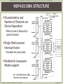
MSP430 DMA STRUCTURE
Characteristics and
Number of Channels are
Device Dependent
Refer to User’s Manual for
specific details
Single Multi-sourced
Interrupt Vector
Encoded for jump table
Enabled for Low-power
Modes support
Fig. 7.40: MSP430x5xx DMA
controller block diagram
© 2014 by M. Jiménez, R. Palomera, & I. Couvertier
Chapter 7: 81
INTRODUCTION TO EMBEDDED SYSTEMS: Using Microcontrollers and the MSP430
MSP430 DMA OPERATION (1/2)
Four Addressing Modes
Address to address
Block to address
Address to block
Block to block
Six Transfer Modes
© 2014 by M. Jiménez, R. Palomera, & I. Couvertier
Chapter 7: 82
INTRODUCTION TO EMBEDDED SYSTEMS: Using Microcontrollers and the MSP430
MSP430 DMA OPERATION (2/2)
Trigger Conditions
Several internal peripheral modules can trigger and initiate a
DMA transfer
Source list is device dependent. Check device’s User’s manual &
data sheet for details
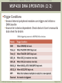
DMA triggering sources in MSP430x5xx devices
© 2014 by M. Jiménez, R. Palomera, & I. Couvertier
Chapter 7: 83
INTRODUCTION TO EMBEDDED SYSTEMS: Using Microcontrollers and the MSP430
END OF CHAPTER 7 SLIDES
© 2014 by M. Jiménez, R. Palomera, & I. Couvertier
Chapter 7: 84