1
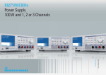
Product Brochure | 01.01 Test & Measurement R&S®HMC804x Power Supply 100 W and 1, 2 or 3 Channels Total output power Output current per channel All models: 100 W HMC8041: max. 10 A HMC8042: max. 5 A HMC8043: max. 3 A EasyArb Create individual V/I curves directly on the device FuseLink Combine electronic fuses as required EasyRamp Program a startup curve directly on the device Sequencing Sequenced start of channels Trigger input Start and control EasyArb, et al. Analog input Control output channel with external voltage and current High energy efficiency Low heat dissipation and quiet fan Brilliant Screen Data logging Protection UI-Tracking QVGA TFT Display with 320 x 240 Pixels To USB flash drive in CSV format Overvoltage (OVP) and Overpower protection (OPP) for all outputs Convenient parallel and serial operation 2 R&S®HMC804x At a glance One, two or three channels – R&S®HMC804x power supplies with their specifications and wide range of functions are ideal for use in development labs and industrial environments. Thanks to their high energy efficiency, the linear power supplies remain cool and quiet, even at maximum load. Practical interfaces and connectors allow users to work quickly and conveniently with the R&S®HMC804x, even in 19“ racks. The R&S®HMC804x family consists of three models with a maximum total power of up to 100 W and a continuous voltage range from 0 V to 32 V. The one-channel R&S®HMC8041 delivers a maximum of 10 A, the two-channel R&S®HMC8042 a maximum of 5 A and the three-channel R&S®HMC8043 a maximum of 3 A per channel. The two-channel and three-channel models enable users to connect multiple outputs in parallel or in series to increase the voltage or current. The outputs are galvanically isolated, floating, and protected against overloading and short circuits. Voltage, current and power values are output on a brilliant QVGA display. The R&S®HMC804x offers a wide range of logging functions, an integrated energy meter and electronic fuses that can be individually combined for each channel, making it ideal for hardware developers, labs and industrial environments. Linear switching power supplies ensure high efficiency, for minimum heat dissipation even at full load. Developers and industrial users benefit from useful functions such as sequenced start of channels, EasyArb and EasyRamp functions that are directly programmable on the device, an analog input for external control of voltage values, an external trigger input for controlling channels and arb steps, and adjustable overvoltage/overpower protection for each channel. All connectors, including SENSE, are available on the rear panel. A cage clamp facilitates rack installation and deinstallation. The LXI-compliant power supply can be controlled via LAN, USB or an optional GPIB interface. The CDC (virtual COM port) and TMC classes are supported for communications via USB. The remote control commands are based on the SCPI standard. The R&S®HMC804x power supplies from the Rohde & Schwarz value instruments product range offer top quality and intelligent, practical functions at an extremely attractive price. R&S®HMC804x 3 Key facts Clear display of all measured parameters ❙❙ Brilliant QVGA color display (320 x 240 pixel) ❙❙ Realtime voltage, current and power values ❙❙ High setting and readback resolution: 1 mV and 0.1 mA/1.0 mA (depending on current and model) ❙❙ Low residual ripple due to linear postregulation ❙❙ High energy efficiency, low heat dissipation and quiet fan Remote control ❙❙ USB interface (CDC/virtual COM port, TMC) ❙❙ LAN interface, LXI-compliant ❙❙ Optional GPIB interface ❙❙ Remote control via SCPI-based commands Galvanically isolated, floating and short-circuit-proof outputs ❙❙ Front panel: 4 mm (0.16 in) safety sockets (R&S®HMC8041 including SENSE) ❙❙ Rear panel: WAGO cage clamp for all channels including SENSE ❙❙ Convenient parallel and serial operation via ❙❙ V/I tracking Protective functions adjustable for each channel ❙❙ Overvoltage protection (OVP) for all outputs ❙❙ Overpower protection (OPP) for all outputs ❙❙ FuseLink (freely combinable electronic fuses) ❙❙ FuseDelay (fuse activation delay) Ideal power supply for hardware developers and labs ❙❙ EasyArb function for user-definable V/I curves ❙❙ EasyRamp for simulating a start-up curve (directly programmable on device) ❙❙ Sequencing (sequenced start of channels) ❙❙ Energy meter (measurement of energy output) ❙❙ Analog input for external control via voltage (0 V to 10 V) and current (4 mA to 20 mA) ❙❙ Trigger input for starting/controlling EasyArb ❙❙ Data logging to USB flash drive in CSV format 4 R&S®HMC804x Application How the HAMEG R&S®HMC804x meets your needs Engineering lab ❙❙ FuseLink (freely combinable electronic fuses) ❙❙ EasyArb function for user-definable V/I curves ❙❙ EasyRamp for simulating a start-up curve (directly programmable on device) ❙❙ Built-in energy meter ❙❙ Data logging to USB flash drive in CSV format ❙❙ Analog input for external control via voltage (0 V to 10 V) and current (4 mA to 20 mA) ❙❙ Trigger input for starting/controlling EasyArb ❙❙ Sequencing (sequenced start of channels) ❙❙ Rear connectors for all channels, including SENSE ❙❙ WAGO cage clamp on the rear panel for easy installation and deinstallation ❙❙ Remote control via SCPI-based commands ❙❙ LAN interface, integrated web server, LXI-compliant ❙❙ Optional GPIB interface (R&S®HMC804xG models) Automatic test equipment (ATE) Production environment Ideal for industrial environments Power supply units in industrial production environments are often found in 19” racks. The HMC804x series instruments are very suitable for this use as all models can be integrated into 19” racks with the rack mounting kits HZC95. Two HMC8043 models built side by side result in 6 channels on 2 rack units. Please ensure sufficient space is available in the rack for adequate cooling (required minimum space above a HMC804x: 1 rack unit). Additionally, all front panel connectors plus SENSE lines are located at the back panel of the instrument. In order to facilitate the regular fitting-out for calibration the rear panel connector was designed with a WAGO cage clamp. The complementary part is available as option HZC40. Base unit Channels Power GPIBInterface R&S®HMC8043G 3 99 W (33 W/Channel, 3 A (max.)) ✔ R&S®HMC8043 3 99 W (33 W/Channel, 3 A (max.)) ✗ R&S®HMC8042G 2 100 W (50 W/Channel, 5 A (max.)) ✔ R&S®HMC8042 2 100 W (50 W/Channel, 5 A (max.)) ✗ R&S®HMC8041G 1 100 W (10 A (max.)) ✔ R&S®HMC8041 1 100 W (10 A (max.)) ✗ R&S®HMC804x 5 ¸HMC8043 ¸HMC8042 ¸HMC8041 Power Supply Voltage all models Current ¸HMC8043 from firmware version 01.104 Electrical Specifications Total power output 100 W 33 W 50 W 100 W 0 V to 32 V Current output ¸HMC8043 ¸HMC8042 ¸HMC8041 max 3 A max 5 A max 10 A Number of outputs ¸HMC8043 ¸HMC8042 ¸HMC8041 3 2 1 Line & load regulation (SENSE connected) Constant voltage mode ¸HMC8043 <0.02% + 3 mV <0.03% + 5 mV Constant current mode <0.03% + 200 µA ¸HMC8042 ¸HMC8041 <0.03% + 300 µA Voltage ripple 20 Hz to 20 MHz (front connector) (V=16 V, I=Imax*0.5) ¸HMC8043 ¸HMC8042 450 µVrms / 4 mVpp ¸HMC8041 all models 1 mVrms / 5 mVpp typ. <1 mArms Response time with SENSE compensation (10 % to 90 % load change) 1 ms (±20 mV) Max SENSE compensation 1 V Programming accuracy (23° C ±5° C) 6 R&S®HMC804x <0.05% + 2 mV Current ¸HMC8043 <0.05% + 2 mA typ. <0.05% + 1 mA (I <100 mA) Positive voltage change no load 10 ms + µC-time with resistive load 10 ms + µC-time Negative voltage change no load 500 ms + µC-time with resistive load 10 ms + µC-time Command processing time <30 ms Over Voltage Protection Yes Over Power Protection Yes Energy Meter Yes EasyRamp Yes EasyRamp time 10 ms to 10 s ¸HMC8042 <0.1% + 5 mA typ. <0.1% + 2 mA (I <100 mA) Electronic Fuse ¸HMC8041 <0.2% + 10 mA typ. <0.2% + 4 mA (I <100 mA) Fuse trip time <10 ms Fuse linking <100 µs + trip time of linked channel Resolution Fuse delay 10 ms to 10 s Voltage Analog Interface all models 1 mV Current ¸HMC8043 ¸HMC8042 0.1 mA (I <1 A) 1 mA (I >1 A) ¸HMC8041 0.5 mA (I <1 A) 1 mA (I >1 A) Voltage to earth 250 VDC Reverse voltage max. 33 V Inverse voltage max. 0.4 V Max. current allowed in case of inverse voltage 3 A Supplemental characteristics Front connectors Rear connectors Current ripple 20 Hz to 20 Mhz (V=16 V, I=Imax*0.5) all models <0.2% +10 mA typ. <0.2% + 4 mA (I <100 mA) Voltage ¸HMC8042 ¸HMC8041 ¸HMC8043 <0.05% + 2 mA typ. <0.05% + 1 mA (I <100 mA) <0.1% + 5 mA typ. <0.05% + 2 mA (I <100 mA) Readback accuracy (23° C ±5° C) Voltage output all models ¸HMC8042 ¸HMC8041 Maximum power per channel ¸HMC8043 ¸HMC8042 ¸HMC8041 Voltage programming speed (within 1 % of total excursion) <0.05% + 2 mV Temperature coefficient ±(% of output + offset) (per K) 4 mm saftey sockets Wago male connector (713-1428/037-000), 8 x 2-pole, pin spacing 3.5 mm / 0.138 in voltage: <0.02 % + 3 mV current: <0.02 % + 3 mA Output voltage overshoot during turn-off of AC power with activated channel output 100 mV Over temperature protection Yes Shunt resistance (4 mA to 20 mA) 250 Ohm Input resistance 0 V to 10 V >10 kOhm Acquisition rate V/I interface 10 Sa/s Response time V/I interface <150 ms Resolution 14 bit Trigger Input Trigger response time <1 ms Min. trigger interval 10 ms Trigger level TTL Edge direction rising, falling Arbitrary (EasyARB) Parameter Voltage, current, time, interpolation mode (y/n) Number of Points max. 512 Dwell time 10 ms to 600 s Repetition rate continous or burst mode with 1 to 255 repetitions Trigger manually, interface, trigger input Logging Sampling rate 1000 Sa/s,100 Sa/s,10 Sa/s, 1 to 3600 Sa/s Resolution ¸HMC8043 1 mV / 0.1 mA (<100 Sa/s) 10 mV / 1 mA (1000 Sa/s) ¸HMC8042 / ¸HMC8041 1 mV / 1 mA (<100 Sa/s); 10 mV / 10 mA (1000 Sa/s) Memory Internal or external memory (USB memory sticks) Maximum number of points limited by memory Output Sequencing Synchronicity <100 µs Delay per channel 1 ms to 60 s Recommended Accessories HZC95 19“ rackmount kit for HMC series, 2 HE HZC40 Female connector with ejectors, 8x2-pole Remote Interfaces Connectors USB-TMC, USB-CDC (Virtual COM), LAN (LXI), GPIB (optional) Miscellaneous Input power option 100 VAC to 240 VAC (±10 %) 50/60 Hz Maximum input power 200 W Fuse T3, 15L 250 V Operating temperature 0 °C to +40 °C Storage temperature -20 °C to +70 °C Humidity 5 % to 80 % Display 3.5” / QVGA Dimensions (H x W x D) 88 x 222 x 280 mm Rack mount capability (half 19“) Yes Weight 2.6 kg HZ72 IEEE-488 (GPIB) bus interface cable HZ10 5x silicon test lead HZ10S: black, HZ10R: red, HZ10B: blue The specifications are based on a 30 min warm-up period. Accessories included: Line cord, printed operating m anual, software-CD Printed operating manual Software-CD Benutzerhandbuch / User Manual Power Supply ¸HMC804x Benutzerhandbuch User Manual R&S®HMC804x 7 value-instruments.com HAMEG Instruments GmbH Industriestr. 6 | 63533 Mainhausen | Germany | Phone +49 (0) 6182 8000 R&S® is a registered trademark of Rohde & Schwarz GmbH & Co. KG HAMEG Instruments® is a registered trademark of HAMEG Instruments GmbH Trade names are trademarks of the owners PD 3607.0169.32 | Version 01.01 | 08 / 2014 | © HAMEG Instruments GmbH Data without tolerance limits is not binding | Subject to change 3607016932 PD 3607.0169.32 V 01.01 PDP1 en www.hameg.com