1
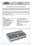
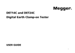
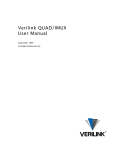
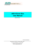
TERM50
User Manual
High Pin Count I/O Interconnection Board
The TERM50 is an interconnection board that eases connection to high I/O count peripheral boards. Its
primary intention is to support I/O connection to the MPL PIP series of industrial PC products.
Typically PC/104 peripheral boards present their I/O’s on two standard raw 0.1 in pin headers up to a total
pin count of 50. MPL AG brings these I/O signals to a mini Dsub connector on the PIP front through an
adapter cable. The TERM50 allows the translation from mini Dsub to individual screw terminals and presents
additional screw terminals for shield connections.
Ó 2001 by MPL AG
1
MEH-10088-001 Rev. B
TERM50
User Manual
TABLE OF CONTENTS
1.
INTRODUCTION .............................................................................................................................................3
1.1
1.2
1.3
1.4
2.
ABOUT THIS MANUAL ..............................................................................................................................3
SAFETY PRECAUTIONS AND HANDLING...............................................................................................3
ELECTROSTATIC DISCHARGE (ESD) PROTECTION ............................................................................3
EQUIPMENT SAFETY................................................................................................................................3
TECHNICAL DATA ..........................................................................................................................................4
Electrical Characteristics: ...................................................................................................................................4
3.
3.1
4.
GENERAL DESCRIPTION ..............................................................................................................................4
PARTS LOCATION.....................................................................................................................................4
PREPARATION FOR USE ..............................................................................................................................5
4.1 BASIC APPLICATION ................................................................................................................................5
4.2 STACKED APPLICATION ..........................................................................................................................5
4.2.1
BASE TERM50 ..................................................................................................................................6
4.2.2
INTERMEDIATE TERM50 .................................................................................................................6
4.2.3
TOP TERM50.....................................................................................................................................7
5.
5.1
5.2
5.3
6.
6.1
6.2
CONNECTION TO THE TERM50 ...................................................................................................................8
I/O CONNECTOR .......................................................................................................................................8
SCREW TERMINAL CONNECTION ..........................................................................................................8
FIXTURE OF THE CABLES .......................................................................................................................8
SUPPORT INFORMATION .............................................................................................................................9
DIN-RAIL MOUNTING KIT .........................................................................................................................9
MPL AG.......................................................................................................................................................9
Ó 2001 by MPL AG
2
MEH-10088-001 Rev. B
TERM50
User Manual
1. INTRODUCTION
1.1 ABOUT THIS MANUAL
This manual assists the installation of the TERM50 screw terminal adapter and provides the specifications
for save operation of this adapter.
This manual is written for technical personnel!
1.2 SAFETY PRECAUTIONS AND HANDLING
For personal safety and safe operation of the TERM50, follow all safety procedures described here and in
other sections of the manual.
· Remove power from the system before installing (or removing) the TERM50 to prevent the possibility of
personal injury (electrical shock) and/or damage to the product.
· Handle the product carefully; i.e., dropping or mishandling the TERM50 can cause damage to assemblies
and components.
· Do not expose the equipment to moisture.
WARNING
There are no user-serviceable components on the TERM50.
1.3 ELECTROSTATIC DISCHARGE (ESD) PROTECTION
Even though there are no electrical components within the product that are sensitive to static and
electrostatic discharge (ESD) you should follow the common precautions to avoid electrostatic discharge to
protect the connected products!
1.4 EQUIPMENT SAFETY
Great care is taken by MPL that all its products are thoroughly and rigorously tested before leaving the
factory to ensure that they are fully operational and conform to specification. However, no matter how reliable
a product, there is always the remote possibility that a defect may occur. The occurrence of a defect on this
device may, under certain conditions, cause a defect to occur in adjoining and/or connected equipment. It is
the user’s responsibility to protect such equipment when installing this device. MPL accepts no responsibility
whatsoever for such defects, however caused.
Ó 2001 by MPL AG
3
MEH-10088-001 Rev. B
TERM50
User Manual
2. TECHNICAL DATA
Electrical Characteristics:
Current rating:
500 mArms per line
1 Apeak per line
30 VDC line to line and line to shield
Voltage rating:
-
Mechanical Characteristics:
Module size:
160 x 70 x 17 mm (excluding mechanical fixtures)
Connector/Screw Terminals:
I/O-connector:
Screw terminals:
Mini Dsub 50 female with latch
3.81 mm spacing
2
Applicable wire size 0.14-1 mm (AWG 26-16)
3. GENERAL DESCRIPTION
The TERM50 is a simple interconnection board that breaks out the signals of a 50 pin mini Dsub connector
to easy-to-connect screw terminals. In addition there are screw terminals to connect cable shields as well as
open areas to directly connect the cable shields to the PCB together with mechanical parts.
The layout is such that the lines are separated from each other by a shielding track thus minimizing electrical
crosstalk to analog I/O signals.
3.1 PARTS LOCATION
155.0 mm
4.7 mm
146.0 mm
Ø 3.3 mm
70.0 mm
61.0 mm
4.5 mm
Ø 3.3 mm
I/O connector
Mounting holes in
PCB edges
Ó 2001 by MPL AG
I/O screw
terminals
Shielding areas
4
Cable fastening
holes
MEH-10088-001 Rev. B
TERM50
User Manual
4. PREPARATION FOR USE
Together with the TERM50 comes a set of mechanical parts. Depending the intended use they are required
or not. Two basic configurations can be built with these parts. For a third kind of mechanical fxture – to a DIN
rail – MPL provides a separate kit. For detailed ordering information refer to section 5.
4.1 BASIC APPLICATION
The basic application is where the interconnections are made by one or more TERM50’s each placed
individually on a working surface. For this following parts out of the set of mechanical parts are required:
4 rubber standoffs with integrated screw M3x6
4 nuts M3
Nut M3
TERM50 PCB
Rubber standoff
The illustration shows how the rubber standoffs are mounted one in each mounting hole at the PCB edges.
4.2 STACKED APPLICATION
The stacked application is the case where two or more TERM50’s are placed on top of each other on a
working surface. In this configuration the base TERM50 must be distinguished from the intermediate
TERM50 and the top TERM50.
NOTE:
Do not stack more than three TERM50 because of mechanical instability!
NOTE:
Make connections to the screw terminals before stacking the boards. Screw terminals are not accessible
once the boards are stacked.
Ó 2001 by MPL AG
5
MEH-10088-001 Rev. B
TERM50
User Manual
4.2.1 BASE TERM50
The lowest board in the stack is placed on the working surface and thus requires the standoffs as in the
basic application. The parts required are
4 rubber standoffs with integrated screw M3x6
4 spacers M3x18
Spacer M3x18
Base TERM50
Rubber standoff
The figure shows the assembly of the parts in the mounting holes of the PCB. After the wires are connected
to the screw terminals the intermediate TERM50 can be mounted as detailed below.
4.2.2 INTERMEDIATE TERM50
It is placed on top of the base TERM50. To fasten it on the spacers of the lower board the following
mechanical parts are required:
4 spacers M3x18
Spacer M3x18
Intermediate
TERM50
Base TERM50
After connecting the wires to the screw terminals you can mount the top TERM50.
Ó 2001 by MPL AG
6
MEH-10088-001 Rev. B
TERM50
User Manual
4.2.3 TOP TERM50
The top TERM50 is the end of the stack and therefore just requires
4 nuts M3
to fasten it to the intermediate TERM50.
Nut M3
Top TERM50
Intermediate
TERM50
Base TERM50
Ó 2001 by MPL AG
7
MEH-10088-001 Rev. B
TERM50
User Manual
5. CONNECTION TO THE TERM50
5.1 I/O CONNECTOR
The connector used is from the AMPLIMITE .050 series III from Tyco/AMP. The part number is
0-787082-5
The cable included with the TERM50 allows a one-to-one wiring to the MPL standard I/O connector of the
PIP series industrial computers. The pin numbering scheme is as illustrated below (front view):
25
1
50
26
For customers not intending to use the included cable the following are some examples of similar connectors
from Tyco/AMP:
750913-5
749111-4
749621-5
1-390377-5
For further details see also
www.amp.com
5.2 SCREW TERMINAL CONNECTION
For easy access the screw terminals are grouped in blocks with five signal terminals and one shield terminal.
Additionally the corresponding pin number of the I/O connector is marked in front of the terminal on top and
bottom of the board.
5.3 FASTENING OF CABLES
In front of each terminal block is an area that allows easy shielding and mechanically fastening of cables.
Simply pull a tie wrap through the two holes and tie the cable with its blank shield to the shielding area of the
TERM50.
Two additional shielding areas can also be found on the short edge of the TERM50.
Ó 2001 by MPL AG
8
MEH-10088-001 Rev. B
TERM50
User Manual
6. SUPPORT INFORMATION
6.1 DIN-RAIL MOUNTING KIT
A DIN rail mounting can be ordered under the following part number:
DRM50-1
It consists of a baseplate with a DIN rail mounting clamp and the necessary screws to mount the TERM50.
6.2 MPL AG
In case of questions contact MPL AG or your local distributor.
MPL AG home page:
Email address:
Ó 2001 by MPL AG
www.mpl.ch
[email protected]
9
MEH-10088-001 Rev. B
TERM50
User Manual
This Page is intentionally left blank!
Ó 2001 by MPL AG
10
MEH-10088-001 Rev. B
TERM50
User Manual
This Page is intentionally left blank!
Ó 2001 by MPL AG
11
MEH-10088-001 Rev. B
TERM50
User Manual
COPYRIGHT AND REVISION HISTORY
Copyright Ó 2001 by MPL AG Elektronikunternehmen. All rights reserved. Reproduction of this document in
part or whole by any means is prohibited, without written permission from MPL AG Elektronikunternehmen.
This manual reflects Revision A of the TERM50.
DISCLAIMER
The information contained herein is believed to be accurate as of the date of this publication; however, MPL
AG will not be liable for any damages, including indirect or consequential, arising out of the application or use
of any product, circuit or software described herein.
MPL AG reserves the right to make changes to any product herein to improve reliability, function or design.
TRADEMARKS
Brand or product names are trademarks and registered trademarks of their respective holders.
Our local distributor:
Ó 2001 by MPL AG
12
MEH-10088-001 Rev. B