1
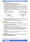
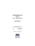
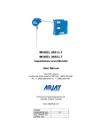
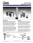
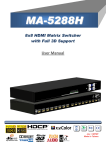
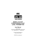
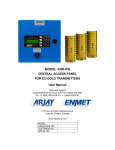
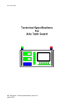
MODEL 2882 CAPACITANCE LEVEL TRANSMITTER User Manual Technical Support Continental North America Toll Free 1-(800) 387-9487 Ph: +1 (905) 829-2418 Fx: +1 (905) 829-4701 A Product of Arjay Engineering Ltd. Oakville, Ontario, Canada www.ArjayEng.com Model: 2882 2882 User manual10.docx Rev: 1.0 TABLE OF CONTENTS 1.0 2.0 3.0 4.0 5.0 INSTRUMENT OVERVIEW ............................................................................................3 1.1 Features .............................................................................................................3 1.3 Specifications .....................................................................................................3 INSTALLATION...............................................................................................................4 2.1 Probes ................................................................................................................4 2.2 Probe installation................................................................................................4 2.3 Electrical Installation ..........................................................................................6 STARTUP AND CALIBRATION ......................................................................................7 3.1 Startup ................................................................................................................7 3.2 Menu Flow Chart ................................................................................................7 3.2.1 Menu Description.................................................................................7 3.2.2 Menu Flow Chart .................................................................................7 3.2.3 Data Entry............................................................................................7 3.3 2882 Transmitter Calibration..............................................................................13 3.3.1 Auto Calibration ...................................................................................13 3.3.2 Manual Calibration...............................................................................13 SETUP AND NETWORK ................................................................................................14 4.1 2882 Transmitter Setup .....................................................................................14 4.2 2882 Transmitter Relay Setup ...........................................................................14 4.3 2882 Transmitter Network ..................................................................................15 TROUBLESHOOTING ....................................................................................................16 2 Model: 2882 2882 User manual10.docx 1.0 INSTRUMENT OVERVIEW 1.1 Features 1.3 Rev: 1.0 Microprocessor Level Transmitter 4-20mA output with optional signal isolator Modbus protocol via RS-485 for access by Arjay handheld, Central Access Panel or compatible system Local 2 point Auto or Manual calibration or remote calibration via network 2 Differential Alarm relays (SPDT, 10 A @ 250 VAC) User specified custom features may be added by contacting Arjay Engineering Ltd. Specifications Power Input: 100 -240 VAC, 50/60 Hz, 0.15A 24 VDC or 12 VDC, 0.25 A Max (specify at the time of order) User Interface: Display & Keypad Two line LCD with % display of Level, select menu or enter values by keypad Communication Interface: RS-485 Modbus Analog /Relay Outputs: mA Signal Output 4-20 mA DC, 900 Ohms max (24VDC), (10bit ) isolated (optional) Relay Output 2 SPDT relay, 10 A @ 250 VAC contacts, selectable failsafe or non-failsafe, selectable high or low acting alarm, programmable time delay: 0 – 600 seconds Instrument Performance: Measuring Range 0 - 1000 pF (most applications are 100pF to 500pF) Accuracy 0.5% of FS on 4-20mA 0.2% of Level or FS capacitance via network display. Resolution 0.5% of FS Level on 4-20 / 0-20mA output 0.05% of Level via network display 0.002% of FS capacitance via network display Calibration 2 point Auto calibration and Manual calibration Environmental Requirement: Operating Temperature -20 - 60 Deg C (Transmitter) Relative humidity 0 to 95% (non-condensing) Mechanical Specification: Enclosure Type Class I Group B, C & D; Class II Group E, F & G; Class III enclosure Type 3 & 4 Weight 2.5 Kg (5.5lbs) max. (excluding probe) Probe length is customer specified. 3 Model: 2882 2.0 2882 User manual10.docx Rev: 1.0 INSTALLATION NOTE: If any damage to the instrument is found, please notify an Arjay Engineering representative as soon as possible prior to installation. 2.1 Probes The 2882 Level Transmitter consists of the transmitter enclosure fitted with a capacitance probe selected from a variety of styles for use with liquids, liquid interfaces, and granular materials. The probe length is customer specified for the tank and depth of material to be measured. Usually Teflon coated probes are used. 2.2 Probe installation Standard probe entry into a tank is via a 3/4" NPT opening (standard probes) or 1" NPT opening (heavy duty probes). Flanges and concentric shields are available as options. The entrance configuration may vary depending on the application requirements. TO SCREW IN PROBE (THREADED ENTRY) USE WRENCH ON LOWER FITTING ONLY. The probe fittings are compression type with Teflon ferrules assembled by applying torque between the two hex sections. The fittings are sealed at the factory to provide a compression seal capable of withstanding high pressures. Once opened they cannot be reassembled without new ferrules. The probe should be mounted vertically and parallel to a reference ground surface, which is typically the vertical wall of the tank or a concentric shield around the probe. The following points are important when installing the probe: 1- Reference ground: This is VERY IMPORTANT and is typically the metal walls of the tank. For non-metallic tanks, a concentrically shielded probe is required in which case the shield provides its own Ground. IMPORTANT: For standard threaded entry and flange entry probes (without concentric shields), make sure the fittings are clean to ensure a GOOD ELECTRICAL CONNECTION BETWEEN THE PROBE HEAD ENCLOSURE AND THE TANK (REFERENCE GND). 2- The distance between the probe and the ground reference: This only applies to probes without concentric shields. The closer the distance to the tank wall, the greater the sensitivity of measurement; too close and bridging problems may occur. 3- The degree of parallelism between the probe and the reference ground: The probe must be parallel to the reference ground for a linear output signal. Note: the concentric shield option is inherently linear due to the concentric shield. 4- The measurement accuracy is affected by the temperature change of the material in the tank. The amount of measurement error depends on the material. If the temperature change is excessive, temperature correction will be required. Contact the Arjay representative for more information. 5- Agitators or moving objects in the tank: Moving objects in the tank close to the probe such as agitator blades, moving baffles etc. appear as moving ground references to a capacitance probe and will cause measurement errors. In applications where these objects are present, a concentrically shielded probe should be used. CAUTION: INSTALL PROBE WITH CARE: DAMAGE TO TEFLON SHEATH WILL CAUSE MEASUREMENT ERRORS. 4 2882 User manual10.docx Model: 2882 THREADED ENTRY FLANGED ENTRY Rev: 1.0 CONCENTRIC SHIELD ENTRY Use wrench on Lower Hex ONLY 2" Entry Typical 1- For threaded and flanged entry types, the probe must be parallel to the tank wall 2- For threaded and flanged entry types, measurement sensitivity is increased by reducing the probe to wall distance. 3- There should be good electrical conductivity between the tank wall and the transmitter enclosure. (For probes with a concentric shield this is not important). INSTALL PROBE WITH CARE: IF TEFLON COATING IS DAMAGED, THE PROBE WILL NOT WORK Figure 2.0 5 2882 User manual10.docx Model: 2882 2.3 Rev: 1.0 Electrical Installation Relay 1 Output RS485 Output + _ Relay 2 Output 24VDC Power Input 4-20mA Output G _ + + _ ½ amp Slow Blow Fuse Probe Input Figure 2.1 1. Power Input 24VDC power input: connect +VDC and – VDC to connector +24 and –24. Earth ground is connected to G. 2. Probe Input Probe input is wired by the factory. The terminal block is disconnected during shipment and has to be re-connected during installation. 3. Network Output Connect “RS485 + and –“to the network D+ and D-. 4. 4-20 mA Output The 4-20 mA is a sourced output referenced to Ground. It is not loop powered. 5. Relays Output 2 SPDT relay, 10 A @ 250 VAC contacts, selectable failsafe or non-failsafe, selectable high or low action, programmable time delay: 0 – 600 seconds 6 2882 User manual10.docx Model: 2882 3.0 STARTUP AND CALIBRATION 3.1 Startup Rev: 1.0 Power up the 2882 transmitter. The status LED should be green. The LCD should go to the normal operating menu. See section 3.2.2 Menu Flow Chart. The unit is normally pre-configured and tested at the factory. A field calibration is required on startup. See section 3.3 <2882 Transmitter Calibration> to calibrate the transmitter . 3.2 Menu Flow Chart 3.2.1 Menu Description The 2882 transmitter has a password protect feature. The default password is 2000. Since the 2882 transmitter has a small LCD, some menu descriptions may be in short form. The following are the menu descriptions: Diags: Cal Pts: Auto Cal: Man Cal: Cal Ok: Cal Err: mA out: mA Span: Sec: Alrm: Alrm Lvl: Diff Hi: Diff Lo: Alrm Del: ^SP: vSP: Diagnostic Calibration points Auto calibrate Manual calibrate Calibrate ok Calibrate err mA output mA output span Second Alarm Alarm level Hi alarm set value Lo alarm set value Alarm Delay Relay Hi action Relay Low action 3.2.2 Menu Flow Chart The 2882 transmitter will display the % level value in its normal operating condition. From the normal operating menu, you can select the Calibrate Menu, Alarm Setup Menu, Diagnostic Menu and Setup Menu. Calibrate Menu includes auto calibrate and manual calibrate, see section 3.3 Calibration for detail description. Alarm Setup Menu provide alarm set point value, alarm low or high action, selectable failsafe or non-failsafe, selectable 0-600 seconds delay. See section 4.2 2882 Transmitter Relay Setup Diagnostic Menu provides current calibration values, frequency and capacitance value. Setup Menu includes Setup View and Setup Change submenus. In the Setup View submenu, the user can only view the setup parameters (mA output direction, mA output span, ID number, etc). In Setup Change submenu, the user can change setup parameters by defaults and customer determined own setup values. The next 5 pages show the detailed menu flow chart. 3.2.3 Data Entry Data Entry Press < > / < > key to increase / decrease the digital value. Press <SELECT> key to move the cursor. 7 Model: 2882 2882 User manual10.docx 8 Rev: 1.0 2882 User manual10.docx Model: 2882 Rev: 1.0 CALIBRATION MENU SELECT CALIBRTE Press <SELECT> Password ____ Password = 2000 See Note 1 for Entry password Press <SELECT> Press <SELECT> Calibration Auto Cal Press < > Press < > Press < > Press < > Press <SELECT> Calibration Man. Cal Press < > #1 % 0.0 Input 1st point level % value See Note 1 for value Entry Press <SELECT> to accept Input 1st point level % value See Note 1 for value Entry Press <SELECT> to accept #1 pF xx.x #2 % 100.0 xxx.x pF Input 2nd point level % value See Note 1 for value Entry Press <SELECT> to accept or > Press <SELECT> #1 %_ _ _0.0 xx.x pF Cal. Err Press < #2 Input 1st point capacitance value See % Note 1 for value Entry Press <SELECT> to accept 100.0 Cal. OK Input 2nd point level % value See Note 1 for value Entry Press <SELECT> to accept #2 pF xxx.x Input 2nd point capacitance value See Note 1 for value Entry Press <SELECT> to accept Cal. Err or Cal. OK Note 1: Data Entry Press < > / < > key to increase / decrease the digital value. Press <SELECT> key to move the cursor. 9 Calibration Exit 2882 User manual10.docx Model: 2882 Rev: 1.0 ALARM SETUP MENU SELECT Alarms Press <SELECT> Password ____ Password = 2000 See Note 1 for Entry password Press <SELECT> Press <SELECT> RELAYS Relay 1 Press < > Press < > RELAYS Relay 2 Press < > Press < > Press <SELECT> # Press <SELECT> RELAY 1 Alrm Lvl Press < Press < Press <SELECT> Diff Hi ___0 Press < > Press < > Press<SELECT> > > RELAY 1 Delay Press < Press < > > RELAY 1 Action Press < > Press < > RELAY 1 Failsafe Press < > Press < > Press <SELECT> Press<SELECT> Alrm Del ___0 Press <SELECT> RELAYS Exit Action Alrm=^SP Press <SELECT> Press<SELECT> Action Alrm=VSP Press<SELECT> Diff Lo ___0 Press<SELECT> Press <SELECT> Failsafe Yes Failsafe No Press<SELECT> Press<SELECT> - See Note 1 # - Relay 2 has the same setup menu of Relay 1 Note 1: Data Entry Press < > / < > key to increase / decrease the digital value. Press <SELECT> key to move the cursor. 10 RELAY 1 Exit Model: 2882 2882 User manual10.docx 11 Rev: 1.0 Model: 2882 2882 User manual10.docx 12 Rev: 1.0 2882 User manual10.docx Model: 2882 3.3 Rev: 1.0 2882 Transmitter Calibration Power up the 2882 transmitter. The status LED should be green. The LCD should go to the normal operating menu (See section 3.2.2 Menu Flow Chart) after the series of following screens (each display for 2 sec.): Arjay S XXXXXX SW X.XXX 2882 Net ID: X HW X.X 3.3.1 Auto Calibration As per the Menu Flow Chart, press Menu key until ¨CALIBRATE shows on display¨. Press select key, enter password ¨2000¨ and confirm that calibration is required, continue to the Auto calibration menu. 1. In the 1st point entry menu, enter the current level value in % (e.g. 0.0%, or 50%). See section 3.2.3 for value entry description. Confirm the capacitance value in pF is stabilized, press <SELECT> key to accept the 1st point value. The 1st calibration point has been done. The LCD should go to the 2nd point entry menu. 2. CHANGE THE LEVEL IN THE VESSEL BY A MINIMUM OF 10%. The level may be raised or lowered. A change of less than 10% may be used in some applications but is not recommended to ensure calibration accuracy. 3. In the 2nd point entry menu, enter the current level value in % (e.g. 100%, or 30%). See section 3.2.3 for value entry description. Confirm the capacitance value in pF is stabilized, press <SELECT> key to accept the 2nd point value. The 2nd calibration point has been done. If the calibration is successful, the display will show “Cal Ok” for a couple of seconds then go back to the calibration menu. If the display shows “Cal Err”, then a calibration fault has occurred. Check the following: 1. The 2nd level entry value is accidentally left at the 1st calibration point % level. Re do the auto calibration according the above steps 1 – 3. 2. The level in vessel was not changed from the 1st calibration point. Re do the auto calibration according the above steps 1 – 3. 3. IF 1 or 2 are not the cause then call Arjay Engineering Ltd.: Toll free: (800) 387 – 9487 (North America Only), tel. +1 (905) 829-2418 3.3.2 Manual Calibration The manual calibration is typically used after successful automatic calibration. This feature allows you to recalibrate the transmitter without physically changing the level in the vessel. For example, if the capacitance and level in % have been recorded after the automatic calibration, these recorded values can be used in the manual calibration. To view the current calibration values at any time, see section 3.2.2 Menu Flow Chart, in Diagnostic menu, under “Diags Cal pts”. To manually calibrate the transmitter: See detail manual calibration procedures in section 3.3.2 Menu Flow Chart, under “SELECT Calibration” Menu and “Calibration Man. Cal” submenu. THIS COMPLETES THE SETUP AND CALIBRATION PROCEDURE FOR THE 2882 LEVEL TRANSMITTER 13 Model: 2882 2882 User manual10.docx 4.0 SETUP AND NETWORK 4.1 2882 Transmitter Setup Rev: 1.0 The 2882 transmitter has the following setup parameters: 1. mA Output For Direct mA output, 0% level = 4 mA, span level (e.g. 100%) = 20 mA; For Inverse mA output 0% level = 20 mA; span level = 4 mA. See section 3.2.2 Menu Flow Chart, SELECT SETUP menu for details to change the mA output action. 2. mA Outpt Span The mA output span may be set anywhere within the measurement range. Normal mA Span is set at 100% level, but this span value can be changed to a required level. See section 3.2.2 Menu Flow Chart, SELECT SETUP menu for details to change the mA Span. 3. Filter (Data Filter) Data filter is used to smooth data from a sudden change and minimize fluctuating readings. For example, a 5 second setting means the calculated value of the capacitance and resulting values of level will take 5 seconds to reach their final values as a result of a sudden change of the level. See section 3.2.2 Menu Flow Chart, SELECT SETUP menu for detail, to change the Data Filter. 4. Device ID number The ID number is used only for network applications. To communicate on a network, each controller must have a unique ID number. Important: if multiple units on a network have the same address, network errors will result. See section 3.2.2 Menu Flow Chart, SELECT SETUP menu for details to change the ID number. 4.2 2882 Transmitter Relay Setup 2880 Transmitter allows 4 parameters per relay plus a time delay value, which is common to all relays: 1. HIGH ALARM (Diff Hi) POINT. This value is specified in % level. Above this value, relay action is taken depending on the Relay Action and Failsafe settings. 2. LOW ALARM (Diff Lo) POINT. This value should be less than the High control point. Below this value, relay action is taken depending on the Relay Action and Failsafe settings. 3. RELAY ACTION . High or Low Action. For high action, the alarm is set when the % level rises above the high alarm set point and is reset when the % level drops below the low alarm set point. For low action, the alarm is set when the % level drops below the low alarm set point and is reset when % level rises above the high alarm set point. 4. FAILSAFE. Failsafe typically means that the relay is normally (when not in an alarm condition) held in an energized state. In an alarm condition, the relay is de-energized i.e. identical to when the instrument power is shut off. The rationale is that the alarm condition should match the Power Fail condition. 5. RELAY DELAY. Minimum time in seconds for an alarm to exist before the corresponding relay is set to its alarm state. The relay alarm state depends on the Relay Action and Failsafe settings. 14 2882 User manual10.docx Model: 2882 Rev: 1.0 The following table shows the effect of the Relay Action and Failsafe settings. Relay Action Failsafe Setting High No High Yes Low No Low Yes 4.3 Effect Alarm condition when process level rises above the High Setpoint for at least the alarm delay period. Alarm condition remains active until the process level drops below the Low Setpoint. No action is taken when the process level is between the High and Low Setpoints. In the alarm condition, the corresponding alarm LED is turned ON, and the relay is energized. Alarm condition set and reset as above. In the alarm condition, the corresponding alarm LED is turned ON, but the relay is de-energized. Alarm condition when process level drops below the Low Setpoint for at least the alarm delay period. Alarm condition remains active until the process level rises above the High Setpoint. No action is taken when the process level is between the High and Low Setpoints. In the alarm condition, the corresponding alarm LED is turned ON, and the relay is energized. Alarm condition set and reset as above. In the alarm condition, the corresponding alarm LED is turned ON, but the relay is de-energized. 2882 Transmitter Network The 2882 Level Transmitter may be monitored and calibrated via RS-485 protocol compatible digital communications. Typical features are: 1. Ease of wiring in multiple level point monitoring: Up to 255 Model 2882's (or other Arjay 2800 Series level monitors) may be connected together in a daisy chain (2 wire communication plus power wiring) connection to an Arjay Remote Access monitor or customer control system which allows viewing data and setup of any of the transmitters on the network. The 4-20mA output may still be used if necessary. 2. Setup for the 2882 for network operation: Each 2882 transmitter must have a unique number to connect in a network system. See section 3.2.2 Menu Flow Chart, SELECT SETUP menu for details to change the ID number. 15 2882 User manual10.docx Model: 2882 5.0 Rev: 1.0 TROUBLESHOOTING CONDITION DO THIS 1. Status LED is OFF and the LCD display if off Check the power to the unit. If the unit is a 24/12VDC model, check the external source is 24V/12VDC. Make sure the polarity is correct. If the unit is a 100-240VAC model, then check the Line, Neutral and Ground wiring is correct. 2. If the status LED is RED This indicates a major error such as memory failure, no probe signal etc. Check the following: 3. mA output does not match the level. Make sure the probe wiring is correct. Microprocessor may have lost its parameters due to a surge in the line. Go to Diagnostic Menu (see 3.2.2 Menu Flow Chart) to check the Calibration values, frequency and capacitance values Call Arjay Technical Support. First determine if the problem is in the mA output or if the unit is not calibrated to the vessel. Check the calibration values, go to Diagnostic Menu (see 3.2.2 Menu Flow chart) and read the 2 calibration points values. If the calibration values are not correct, redo calibration (see section 3.3 2882 Transmitter Calibration) If the calibration values are correct, go to next step to check mA output. Check the mA output Action (direct or inverse) and mA output Span are set as desired. See section 3.2.2 Menu Flow chart / Setup/ View menu. If the mA output still does not match the level, then call Arjay Technical Support. IMPORTANT: THE UNIT SOURCES mA OUT FROM THE mA OUTPUT TERMINAL. THIS TERMINAL SHOULD NOT BE CONNECTED TO +24V. IT IS NOT A 2 WIRE mA TRANSMITTER. See Figure 2.1 for electrical hookup details ARJAY ENGINEERING TECHNICAL SUPPORT (800) 387-9487 +1 (905) 829-2418 www.arjayeng.com 16