1
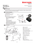
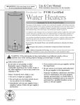
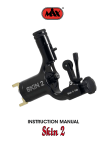
User Manual
ENGLISH
HardLock
S45, S50, S60, S70, S80
Congratulations on your SMP purchase!
Carefully study this user manual before using the product.
The manual explains the safety aspects for using this product and
how to get the most out if it to maximize the products life span.
Take care of your SMP product and it will take care of you!
Welcome as our customer to SMP Parts AB.
Do not hesitate to contact us for further information.
www.smpparts.com
Contents
Introduction
About This Manual
General
Declaration Of Conformity
Identification Plate
4
4
5
5
Safety
Safety and Warnings
6
Technical Specifications
Dimensions
8
Installation
Installation
Demounting an Existing Quick Coupler Mounting the HardLock Quick Coupler
Connecting the Hydraulics
Pre Delivery Inspection
9
9
10
11
12
Operation
Attachment
Detachment
Troubleshooting
13
16
18
Service and Maintenance
Service and Maintenance
Lubrication Chart
19
20
Spare Parts
Spare Parts List
21
3
Introduction
About This Manual
This user manual is intended to be used together with the SMP HardLock quick
coupler during installation, operation and regular maintenance.
This manual is a guide of how to use and maintain the quick coupler in the correct
way.
SMP reserves the right to change the contents of this manual at any time and
without prior notice. This user manual can be ordered at SMP Parts.
The operator of the equipment must carefully study and make sure to fully
understand this manual before using the equipment. The safety information given in
this manual is only covering the SMP HardLock fastening equipment independent of
the carrier machine and tools.
This user manual is an original instruction according to the machinery directive.
General
The SMP HardLock is a quick coupler used for attachment of buckets and tools to a
carrier such as an excavator or similar. From here we will use the word excavator.
The quick coupler is hydraulicaly controlled meaning that changing of buckets and
tools is controlled with the excavator´s hydraulic and control system by the operator.
The quick coupler is equipped with a hook, intended to use for lifting with slings,
lifting chains or similar. The maximum allowed lifting weight is shown on the hook.
The maximum allowed lifting weight of the carrier machine must never be exceeded.
The lifting hook must not be used if the locking mechanism is not working properly
or damaged.
To prevent injury of a person or damage to equipment, read and note all warning
signs and symbols shown on the quick coupler and in this manual before use.
Before operation, check that no unauthorized persons are within the working area of
the excavator.
Before operation, pressurize the quick coupler locking function to check and ensure
that the bucket or tool is perfectly secured.
4
Introduction
Declaration Of Conformity
SMP Parts develop and manfacture all products in
accordance with the european legislations and the
machinery directive 2006/42/EG. Together with the
products delivered there is also a CE certificate that
guarantees that the equipment is manufactured
according to the legislations.
Enlig
Härm
EG-F
ö
t mas
kind
ed
rsäk
irekt
ivet
ran
om ö
förkla
kons
rar
tru
2006
maski ktion oc vi att den
/42/
h
ndire
produ
EC fr
ktive i den versi
känn
kt so
t 2006
edom
on so
m
ån 17
/42/E
ogilti
m ma beskrivs
maj
gförkl
C. Vi
rknad
ne
2006
arar
vill på
sföres dan i de
denn
, Bila
ss utf
av os
a för minna att
ormnin
ga
säkra
ändri s överens
g oc
n.
ngar
Besk
på pro stämmer h
rivnin
me
dukte
g av
n uta d
prod
n vår
ukte
n:
vere
nsstä
mme
lse
II A
Artik
elnum
mer:
Infäs
tning
:
Kund
ordern
umme
Tillve
r:
rkning
snum
Typ:
mer:
Den
över
stä
Arbe
tsmilj mmer oc
kså
över
med
kets
följa
före
nde,
skrif
för pr
t: AF
S200
oduk
8:3
ten,
fö
renli
ga
före
skrif
ter.
Ansva
rig för
den
Börje
teknis
Blan
ka do
k, Be
kume
rgsjö
ntatio
väge
nen:
n 3,
820
71
ILSB
O.
2014
-1208
Ilsbo
The identification plate gives information about
model designation, serial number, manufacturing
year. There is also a CE-logotype on the plate
indicating that the product fulfill the machinery
directive.
Bergsjövägen 3
SE-820 71 Ilsbo
Art.nr.
Coupler
Type
Volume.
Mfg.nr.
Tooth
Weight
Mfg. Year
kg
Patented
I-SAE
Art.nr 60944
Identification Plate
5
Safety
Safety and Warnings
This chapter describes safety related information that needs to be taken into
consideration before, during and after using the equipment.
DANGER, WARNING, CAUTION and Note statements are used throughout this
manual to emphasize important and critical information. You must read these
statements to help ensure safety and to prevent damage to the product. The
statements are defined below.
DANGER indicates an imminiently hazardous situation which, if not avoided,
will result in death or serious injury. This signal word is to be limited to the most
extreme situations.
WARNING indicates a potentially hazardous situation which, if not avoided, could
result in death or serious injury.
CAUTION indicates a potentially hazardous situation which, if not avoided, could
result in minor or moderate injury. It may also be used to alert against unsafe
practices.
Note: A note statement is used to notify people of installation, operation or
maintenance information that is important, but not hazard-related.
General Warning Signs on Machinery Equipment
WARNING
READ THE USER MANUAL
NEVER STAND UNDER A LOAD
RISK OF CRUSHING BY MOVING PARTS
6
Safety
DANGER!
Never stand under a load! Always keep attention to the machines
working area. Unauthorized persons are not allowed to enter the working
area of the machine during operation. Always ensure that the machine is
completely stopped during maintenance and repairs.
WARNING!
Do not install the quick coupler before you have read and understood
the instructions given in the user manual.
WARNING!
Incorrect installation can affect the safety. If there are any uncertainties,
contact your local dealer or SMP Parts.
WARNING!
Make sure that the hydraulic system does not contain any pressure
before maintenance or repair work. The hydraulic oil is under high
pressure and can penetrate your skin causing serious injury.
WARNING!
Never use your hands when looking for a leakage. The hydraulic oil is
under high pressure and can penetrate your skin causing serious injury.
WARNING!
When the quick coupler is being installed, the load tipping limit must be
checked to prevent and minimize the risk of injury of a person.
WARNING!
Never use equipment attached to the quick coupler if the locking
mechanism is not in locked position.
WARNING!
Use protective clothing when working on the equipment.
7
Technical Specifications
Dimensions
B
C
B
A
Quick coupler type
Length (A)
Shaft dimension
(mm)
(mm)
Height (C)
Width (D)
Max. Hyd. pressure
Weight
(mm)
(mm)
(bar)
(t)
8
D
S45
429,8 ±0,2
S50
429,8 ±0,2
S60
479,8 ±0,2
S70
599,8 ±0,2
S80
669,8 ±0,2
ø 45
ø 50
ø 60
ø 70
ø 80
Max 65
288 ±1
350
5-12
Max 65
268 ±1
350
5-13
Max 80
338 ±1
350
12-18
Max 100
448 ±1
350
17-25
Max 115
588 ±1
350
25-40
Installation
Installation
Before carrying out any installation work, place
the machine and the equipment to be installed
on a clean flat surface without obstacles, with no
inclination since that could result in problems during
installation.
WARNING!
Do not install the quick coupler before you have read and
understood the instructions given in the user manual.
WARNING!
Incorrect installation can affect the safety. If there are any
uncertainties, contact your local dealer or SMP Parts.
Demounting an Existing Quick Coupler
On the excavator quick coupler, disconnect the hydraulics and
fit plugs. Bring out the shafts and remove the quick coupler.
Use the shafts delivered with the quick coupler during the
installation. For some machines the shafts are not supplied
with the quick coupler, the original shafts shall in those cases
be used.
WARNING!
Make sure that the hydraulic system does not contain
any pressure before demounting the pressure hoses to
the locking function. Hydraulic oil under pressure can
penetrate your skin and cause serious injury. Fit plugs
onto the hoses to be able to operate the excavator arm
during the installation.
9
Installation
Mounting the HardLock Quick Coupler
WARNING!
Take extra care when connecting the quick coupler
to the excavator since there is a risk of crushing
hands and fingers.
Tip!
To simplify the installation, place the quick coupler
on a pallet and use a pallet jack to adjust into correct
position.
1. Fit the dust protection o-rings.
2. Operate the dipper arm to place it by the quick
coupler. Use a pallet jack to bring the quick
coupler into position. The shaft holes in the quick
coupler should now be in line with the holes in
the excavator arm.
3. Visually inspect the axial gap between the dipper
arm and quick coupler. If the gap is greater than 3
mm, fit shims.
4. Add oil to the bushings and shaft, fit the shaft and
bring it in completely by gently tapping it with a
soft sledge hammer.
5. Operate the tipping link and align it with the
holes on the quick coupler. Visually inspect the
axial gap between the tipping link and quick
coupler. If the gap is greater than 3 mm, fit shims.
6. Lock the shafts with the locking pins included in
the installation kit.
10
Installation
Connecting the Hydraulics
The type, size and length of hydraulic hoses and
couplings can differ depending on type of excavator.
Therefore it is sometimes neccesary to make new
hoses locally. Ensure that the hydraulic hoses get
the correct length to prevent damage which can be
caused by stretching or crushing.
Make sure that the hydraulic hoses and nipples
are fitted and tightened according to the supplier
recommendations.
The size of hydraulic ports is 1/4” BSP for all models.
WARNING!
Make sure that the hydraulic system does not
contain any pressure before demounting the plugs
on the hoses. Hydraulic oil under pressure can
penetrate your skin and cause serious injury.
Locking and opening pressures:
HardLock type S45 - S80
Locking pressure
Opening pressure
Recommended
Min 150 bar
Max 350 bar
Max 350 bar
NOTE!
All SMP quick couplers are equipped with pilot
controlled check valve, type: 4CK30.
11
Installation
Pre Delivery Inspection
After the installation is completed:
1. Check the functionality.
2. Check for leakages.
3. Attach a bucket or a tool and operate the bucket function to its end positions.
4. Check and make sure that the bucket or tool is perfectly secured and that the hoses are
not stretched or crushed.
5. Grease according to lubrication chart.
6. Clean the equipment before delivery to end customer.
7. Fill up local after sales contact information on the back cover of this manual.
12
Operation
Attachment
WARNING!
It can in some situations be possible to connect
a bucket or tool and ”grab” it with the excenter
locking shaft. This is not allowed at anytime!
Never lift a bucket/tool with the quick coupler not
completely locked.
WARNING!
Before attaching, make sure that both the grid on
the bucket or tool and quick coupler is clean and
free from dirt that could affect the fastening.
DANGER!
Never stand under a load! Always pay attention
to the machines working area. Unauthorized
persons are not allowed to enter the working are
of the machine during operation. Always ensure
that the machine is completely stopped during
maintenance and repairs. Risk zone: three meters!
WARNING!
The lifting hook must not be used if the locking
mechanism is not working properly or damaged.
WARNING!
The maximum allowed lifting weight of the carrier
machine must never be exceeded.
13
Operation
TIP!
The attachment will be easier if the bucket/tool and
the machine is aligned and placed on a flat surface.
1. Check for both indicators to be visible, indicating
that the quick coupler is in open position.
2. Position the quick coupler onto the grid.
3. Operate the tilting function to fit the quick
coupler to the grid.
14
Operation
4. Operate the locking function to fasten and secure
the bucket/tool.
5. The indicator indicates that the quick coupler
is in locked position. Both indicators should be
”hidden”.
6. Carefully check that the bucket/tool is fastened by
carrying out a bend test.
15
Operation
Detachment
WARNING!
Never release the locking mechanism when the
bucket or tool is in a position where it can fall off
the quick coupler.
DANGER!
Never stand under a load! Always pay attention
to the machines working area. Unauthorized
persons are not allowed to enter the working are
of the machine during operation. Always ensure
that the machine is completely stopped during
maintenance and repairs.
1. Place the bucket onto the ground before
disconnecting
2. Unlock the quick coupler by operating the
locking function.
16
Operation
3. Carefully detach the bucket/tool.
17
Operation
Troubleshooting
Insufficient functionality can depend on a number of reasons.
This list explain some of the possible faults to check for.
• Check for blocking material such as stones or similar that
can block the mechanical functions of the quick mount.
• Check for mechanical damage.
• Check the functionality of the excatavor.
• Check for leakage
Make a judgement if the fault can be repaired by yourself or if
a technician need to repair the fault.
WARNING!
Do not carry out any repairs if you do not have the
expertise or knowledge in how to make the repair.
CAUTION!
Always use protective clothing when working on
the equipment.
WARNING!
The machine must always be turned off during
service and maintenance.
18
Service and Maintenance
Service and Maintenance
To get the most out of the products and to
ensure full product life time, regular service and
maintenance is of high importance.
CAUTION!
Always use protective clothing when working on
the equipment.
WARNING!
The machine must always be turned off during
service and maintenance.
Daily Maintenance
• Operate the quick coupler to check its
functionality.
• Visually check shaft locking pins and nuts.
• Check for leakage in the hydraulic system.
• Check for cracks and damage.
• Check that the quick coupler is correctly fastened
both excavator and bucket.
• Clean the quick coupler from dirt.
• Lubricate according to lubrication chart.
• Check for axial play, shim if needed.
• Check the locking mechanism at the lifting hook.
Weekly Maintenance
• Check fastenings on shafts, tighten locking screws
and nuts.
19
Service and Maintenance
Lubrication Chart
Lubricate the quick coupler with grease at least once
per week or after 40 working hours.
(2X)
20
(2X)
Spare Parts
Spare Parts List
7
3
4
6
5
2
8
1
Model
Pos
1
2
3
4
5
6
7
8
S45
208669
208676
76134
67185
–
208968
208665
208668
S50
208669
208676
67134
67185
–
208968
208662
208667
S60
Part number
207810
207685
67098
67135
–
208964
207807
207797
S70
207614
207685
67098
67135
208407
208964
207713
207618
S80
207894
207685
67098
67135
208407
208964
207891
207893
Description
Locking wedge
Shaft
Hydr.cyl
Seal kit
Protection plate
Excenter lock
Excenter
Locking block
21
Notes
22
23
About SMP Parts
SMP is a leading designer and manufacturer of high quality equipment and tools for excavators and backhoe
loaders. Our company prides itself on producing products and solutions that are of the highest quality and
safety standards. We are a very customer focused company and by adapting our products, we can modify the
solution for each customer’s specific challenge or task at hand.
Since 1980 SMP Parts has been developing and producing equipment for mini excavators, tractor loaders
and wheel drive/track drive excavators. Some of the products we offer are quick couplers, excavator
buckets, grading buckets and a range of other accessories.
SMP’s own patented quick hitch was launched in 1983 and in 1985 the Swingotilt® tiltrotator was
developed.
In 1987 the AREMA GROUP AB took over the company and in 1989 SMP began selling to the
Norwegian market.
In 1992 all manufacturing was moved to the present site in Ilsbo, Sweden and a year later a
sales office in Germany opened.
SMP Parts have over 100 employees, most of which work at the factory in Ilsbo, Sweden
but we also have employees in Norway and Germany.
Download a digital copy of this manual
Headquarters / factory
SMP Parts AB
Bergsjövägen 3, SE-820 71 Ilsbo, Sweden
Tel: +46 650 356 50, Fax: +46 650 35660
[email protected]
www.smpparts.com
HardLock User Manual 67186-EN REV2015-04
SMP Parts operates in Sweden, Norway, Finland, Denmark, Germany, England, Spain
and the Benelux countries, with a number of dealers in each country. All development
and manufacturing is carried out in the main headquarters and factory in Sweden.
To meet the requirements of quality, function and finish, SMP has over the years
invested in a modern and efficient fleet.