1
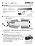
Hercules 2s
User Manual
Introduction
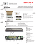
1.1 Product Description
1.2 Box Contents & Tools Required
The box contains the following items:
A Hercules 2s sensor
with pre-wired 23’ (7m) 6-wire cable
B Self-adhesive mounting template
C Instruction manual
B
1/2"
13 mm
Hercules 2s is an advanced planar microwave motion sensor designed for industrial doors and gates. The sensor can differentiate
between people and vehicles. Its two relay outputs can be programmed independently for a multitude of applications. Hercules 2s
also features cross-traffic optimization and slow-motion detection.
1 3/8"
35 mm
Extra height
for tilted device.
1/2"
13 mm
1 1/8"
28 mm
1 1/8"
28 mm
A
Mounting screws
1 3/8"
35 mm
(stores in slot on battery compartment cover)
Tools recommended for installation:
- Ladder
- Tape measure
- Level
- Drill with 1/4” (5mm) drill bit
- Electric screwdriver with
bit to match mounting screws
- AWG 4 (5 mm dia) wire stripper for cable sleeve
- AWG 24 (0.20 mm 2 ) wire stripper for single wires
Other items recommended for installation:
- Mounting screws (x2) sized for 3/16” (5mm) hole
- RC Duo 2 remote control (Part # S-RC2)
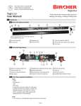
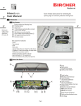
1.3 Parts of the Sensor
"
3/16
5 mm
1 5/8"
41 mm
D Quick reference guide for RC Duo 2 remote control
1/2"
13 mm
Tilt center / prefered cable exit
3/16
5m "
m
4 1/2"
111 mm
1/2"
13 mm
Front view, 45° angle shown
6 1/2"
166 mm
C
EN ISO
9001
Quality
ualit
Q
international
level
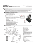
Hercules 2s Quick Guide
Function
Mounting
Height
A
C
B
Field size/
Sensitivity
PP
PP
Output #1
Output #2
PP
0RXQWLQJVFUHZV
PP
PP
PP
PP
PP
1 { 6’6” (2.0 m)
8’ (2.5 m)
2 {
10’ (3.0 m)
3 {
13’ (4.0 m)
4 *{
16’6” (5.0 m)
5 { 19’6” (6.0 m)
6 { 23’ (7.0 m)
1
2
3
4
5
6
7
8
9
= Vehicles forward*
= Vehicles backward
= Vehicles both dir
= People forward**
= People backward
= People both dir
= People/vehicles fwd
= Ppl/veh bkwd
= Ppl/veh both dir
PP
Output
Configuration
Output #1
(Green LED)
Output #2
(Red LED)
PP
7LOWFHQWHUSUHIHUHGFDEOHH[LW
Page 1/2
Remote Values/
Function Description
PP
D
E
1 = X-small/least sens.
2 = Small/less sens.
3 = Medium/norm sens.
4 = Large/very sens.*
5 = X-large/most sens.
)URQWYLHZDQJOHVKRZQ
A
Output
Configuration
Output
Hold time
Output #1
(Green LED)
Output #2
(Red LED)
B
C
Field size/
Sensitivity
Output #1
Output #2
D
E
Output
Hold time
Output #1
F 1
Output #2
F 2
*Factory Settings
Page 1/2
Remote Values/
Function Description
Mounting
Height
Function
Quick reference guide for RC Duo 2 remote control
(stores in slot on battery compartment cover)
Tools recommended for installation:
- Ladder
- Tape measure
- Level
- Drill with 1/4” (5mm) drill bit
- Electric screwdriver with
bit to match mounting screws
- AWG 4 (5 mm dia) wire stripper for cable sleeve
- AWG 24 (0.20 mm 2 ) wire stripper for single wires
Other items recommended for installation:
- Mounting screws (x2) sized for 3/16” (5mm) hole
- RC Duo 2 remote control (Part # S-RC2)
Hercules 2s Quick Guide
Microwave motion sensor for
industrial doors
Hercules 2s is an advanced planar microwave motion sensor designed for industrial doors and gates. The sensor can differentiate
between people and vehicles. Its two relay outputs can be programmed independently for a multitude of applications. Hercules 2s
also features cross-traffic optimization and slow-motion detection.
Box Contents & Tools Required
The box contains the following items:
Hercules 2s sensor
with pre-wired 23’ (7m) 6-wire cable
Self-adhesive mounting template
Instruction manual
% $
Product Description
$"
international
level
EN ISO
9001
Qualit y
Quality
1
Microwave motion sensor for
industrial doors
1 { 6’6” (2.0 m)
8’ (2.5 m)
2 {
10’ (3.0 m)
3 {
13’ (4.0 m)
4 *{
16’6” (5.0 m)
5 { 19’6” (6.0 m)
6 { 23’ (7.0 m)
1 = Vehicles forward*
2 = Vehicles backward
3 = Vehicles both dir
4 = People forward**
5 = People backward
6 = People both dir
7 = People/vehicles fwd
8 = Ppl/veh bkwd
9 = Ppl/veh both dir
1 = X-small/least sens.
2 = Small/less sens.
3 = Medium/norm sens.
4 = Large/very sens.*
5 = X-large/most sens.
1 = 0.2 sec
2 = 0.5 sec
3 = 1.0 sec
4 = 2.0 sec*
5 = 5.0 sec
7 = Pulse on exit
8 = Output steadily on
9 = Output steadily off**
Output #1
F 1
Output #2
F 2
**Factory Settings for output 2
*Factory Settings
1
2
3
4
5
7
8
9
= 0.2 sec
= 0.5 sec
= 1.0 sec
= 2.0 sec*
= 5.0 sec
= Pulse on exit
= Output steadily on
= Output steadily off**
**Factory Settings for output 2
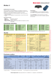
D
K
L
A Housing (aluminum)
B Mounting bracket
C
TOP
C Inclination angle handscrews (x2)
A
D Microwave planar module
J
E Clip for wide detection pattern
F
I
B
C
E
D
F
G
G
H
H
I
TOP
O
N
(Use setting for wide field pattern - sec. 7.2)
Left button L to set function
Right button R to set value
Output 1 indicator (green LED)
Output 2 indicator (red LED)
J DIP switches (for setting
remote control addresses 1-4)
K Rear cover
L Connection cable
N
M Front cover
N
N Cover screws (x4)
M
N
Page 1
O RC Duo 2 remote control
required to access complete set of functions
2
Safety Precautions
2.1 General Safety
Warning: failure to follow these safety precautions may cause damage to sensor or objects, serious personal injury, or death.
-This product is designed to be mounted above an overhead industrial door.
-Do not use this product other than for its specified application.
-Observe all applicable local, national, and international door safety standards, codes, and laws.
-Only trained and qualified personnel may install and initialize the sensor.
-Only authorized Bircher Reglomat personnel may perform hardware/software changes or repairs to the product.
-The unit should only be operated from a safety extra low voltage (SELV) system with safe electrical separation.
-Always consider the safety functions of your applications as a whole, never just in relation to one individual section of the system.
-The installer is responsible for testing the system to ensure it meets all applicable safety standards (e.g. UL-325).
-Never touch any electronic components or lenses.
-After accessing the inside of the sensor, ensure the cover/protection seal is closed tightly to achieve designated protection rating.
2.2 Installation Safety
-Follow all steps outlined in this manual in order for proper installation of the product.
-Stop all traffic through the door before installing sensor.
-Ensure there is no vehicle or pedestrian traffic through the door until sensor is installed and tested for compliance with all applicable
safety standards (e.g. UL-325).
-Verify proper installation of door equipment before installing sensor.
-Shut off all power before attempting any wiring procedures.
-Always use wire terminals to terminate stranded wire ends.
-Check placement of wiring to ensure moving parts are not impeded by wires.
-Make sure wiring is correct before applying power to the sensor to avoid damage to equipment.
-Ensure door & header, including housing components, are properly grounded to protective earth (PE).
-Ensure (e.g. by walk testing) that installation is in compliance with all applicable standards (e.g. UL-325) after completion of installation.
-If the sensor sustains damages (e.g falls), replace it with a new unit.
-If a satisfactory solution cannot be achieved after troubleshooting, please call Bircher Reglomat at 800-252-1272 or
visit our website at www.bircherreglomat.com.
DO NOT LEAVE ANY PROBLEMS UNRESOLVED! DO NOT SACRIFICE SAFETY FOR ANY REASON!
3
Mounting the Sensor
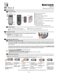
3.1 Special Considerations
Ensure sensor is firmly mounted
on a flat surface. Avoid vibrations.
Objects such as fans, plants,
flags, etc must not protrude into
the detection area.
Page 2
Obstruction can effect performace of sensor. Make sure
sensor has an unobstructed
view.
Mount sensor away from
fluorescent or HID light sources.
3.2 Mounting Instructions
1. Remove sensor unit from mounting bracket by loosening handscrews.
2. Affix the self-adhesive mounting template to the wall or ceiling and drill holes
in specified locations. Remove the template once the holes have been drilled.
3. Route the cable through the opening in the mounting bracket and ensure cable
length is sufficient to accomodate desired inclination angle.
Attaching the sensor to the bracket
4. Secure the mounting bracket tightly to the wall or ceiling using screws.
5. Attach sensor to mounting bracket by aligning the pins and screws on the sensor
with the slots on the mounting bracket. Ensure both sides are seated properly.
Tighten handscrews to secure.
6. Connect cable to door operator (refer to door operator manual for wiring diagram).
Ideal mounting location
Center over door
Self-adhesive mounting template
Extra height
for tilted device.
x
i l
5” (125 mm)
1 5/8” (41 mm) 2” (50 mm)
1 1/8"
28 mm
i
i l
1 1/8"
28 mm
i
"
3/16
5 mm
1 5/8"
41 mm
1/2"
13 mm
Tilt center / prefered cable exit
3/16
5m "
m
1/2"
13 mm
111 mm
i
5” (125 mm)
i
1 3/8"
35 mm
i
x
1/2"
13 mm
Optional ceiling mounting
min. 2”
(50mm)
li
i
45°
i
i
1 3/8"
35 mm
i
Mounting screws
i
i
i
i l
6 1/2"
166 mm
i
1/2"
13 mm
i
Front view, 45° angle shown
i
i
i l
i
i
i
3.3 Inclination Angle
After mounting, adjust the inclination angle to the desired detection pattern. Adjust the inclination angle by loosening the
handscrews on the sides of the sensor and adjusting as shown below. Range is 0 - 90°, in 15° increments as marked on
the mounting bracket. 30 - 45° is typical for most applications.
+
li
i
i
–
i
i
i
i
i
i
i
+
–
3.4 Tilt Angle
8"
1 3/
m
35 m
"
1 1/8
m
28 m
"
1 1/8
m
28 m
1/2"
m
13 m
4 1/ m
m
111
8"
1 5/
m
41 m
6"
3/1 m
5m
1/2"
m
13 m
t
e exi
cabl
fered
/ pre
nter
3/16"
Tilt ce
5 mm
en
fahr
sver
ktion
h
ic
Extrailted dev
for t
od
men
rnom
übe
g
bein
nor
ess
It may be necessary to tilt the sensor for certain applications (not recommended unless warranted by special circumstances).
To do so, loosen the handcrews and remove the sensor from the bracket. Once the mounting screws are accessible, loosen them
enough to twist the bracket to change the tilt of the sensor.
Example of application
requiring tilt adjustment
Mounting screws
s
screw
nting
Mou
, 45°
view
Front
wn
e sho
angl
"
6 1/2
m
166 m
Page 3
h
Extrailte
for t
4
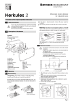
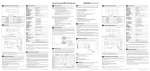
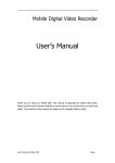
Electrical Connection
Black
10 - 36 VDC/
12 - 28 VAC
Red
Power
White
Cable
Green
COM
NO (NC)
Output 1
(Green LED)
COM
NO (NC)
Output 2*
(Red LED)
Brown
Blue
See table on pages 6 & 7 for detailed information
on output 1
*Factory setting = Output 2 off
See table on pages 6 & 7 for detailed information
on output 2
4.1 Initialization
Startup sequence after power has been connected to the sensor:
-Both green & red LED’s begin to blink slowly
-Green LED will continue to blink quickly
5
Introduction to the RC Duo 2 Remote Control
The RC Duo 2 remote control allows Hercules 2s to be easily and conveniently programmed from the ground. Data transfer between the
RC Duo 2 and Hercules 2s functions in both directions, i.e. to and from the sensor by an infrared interface. The RC Duo 2 reads back the
adjusted values immediately after programming and displays them on the remote to ensure accurate programming.
Flashing buttons on the RC Duo indicate that the data has not been fully transmitted.
Avoid exposing the infrared interface to direct sunlight or other light sources.
5.1 Layout of the RC Duo 2 Remote Control
A Transmitter/receiver (infrared)
B Status indicator LED
C Numerical buttons (1 to 9)
D Function buttons (A to F)
E Start button:
A
F
B
Function
Remote Values/
Function Description
Mounting
Height
A
Output
Configuration
Output #1
(Green LED)
Output #2
(Red LED)
C
B
C
Field size/
Sensitivity
Output #1
Output #2
D
E
Output
Hold time
D
Page 1/2
Hercules 2s Quick Guide
Output #1
F 1
Output #2
F 2
*Factory Settings
1 {
2 {
3 {
4 *{
5 {
6 {
1
2
3
4
5
6
7
8
9
6’6” (2.0 m)
8’ (2.5 m)
10’ (3.0 m)
13’ (4.0 m)
16’6” (5.0 m)
19’6” (6.0 m)
23’ (7.0 m)
= Vehicles forward*
= Vehicles backward
= Vehicles both dir
= People forward**
= People backward
= People both dir
= People/vehicles fwd
= Ppl/veh bkwd
= Ppl/veh both dir
a) Powers on (hold 2 sec)
b) Establishes connection to the sensor
1 = X-small/least sens.
2 = Small/less sens.
3 = Medium/norm sens.
4 = Large/very sens.*
5 = X-large/most sens.
1
2
3
4
5
7
8
9
= 0.2 sec
= 0.5 sec
= 1.0 sec
= 2.0 sec*
= 5.0 sec
= Pulse on exit
= Output steadily on
= Output steadily off**
F Remote function quick reference guide
**Factory Settings for output 2
(stored in slot on battery compartment cover)
This guide is included in every Hercules2s box
E
5.2 Turning on the RC Duo 2 Remote Control
The RC Duo 2 must be powered on before use.
POWER ON: Press and hold G for 2 seconds
POWER OFF*: Press and hold G for 2 seconds
*The remote will automatically turn off after 2 minutes if no button is pressed.
Page 4
Power ON: Press G for 2 sec
5.3 Establishing Connection to the Sensor
The RC Duo 2 functions bidirectionally with the sensor. This means that changes to the settings on the sensor are immediately signalled back by the sensor to the remote control. If an additional parameter is programmed within 2 minutes of the previous parameter,
it is not necessary to press G to re-establish connection to the sensor each time.
Ensure sensor is in
programming mode
(section 6.1)
The sensor’s address illuminates on
the keypad.
Once G blinks, press
G again to establish
connection.
EXAMPLE: address
7 (factory setting)
Choose function to be
programmed. See chart
on following pages for
complete list.
The sensor ackNow press desired
nowledges it’s current new value.
setting by illuminating
it on the keypad.
EXAMPLE:
Desired height =
Press the desired
EXAMPLE:
11 ft 3” (3 m)
function (letter) button. 4 =13-16’6” ft (4-5 m) Choose 3 = 10 - 13’
(factory default)
(3-4 m)
EXAMPLE: mounting
height A
The new setting is
immediately saved
and displayed on
the keypad.
Programming of
this function is now
complete. Repeat
for other functions
if necessary.
Note: If any buttons are blinking, programming failed. In this case, repeat programming.
6
Functions & Settings - Programming by Remote Control
6.1 Entering Sensor Programming Mode
The connection between the RC Duo 2 and Hercules 2s can only be established when the sensor is in programming mode (unlocked).
Programming mode is activated when the sensor is switched on. For safety reasons, this mode is automatically deactivated 30 minutes
after the last setting has been made on the sensor. The sensor can be locked at any time by pressing F 8 followed by 8 .
Programming mode can be activated in three different ways:
A) Restart the sensor (temporarily disconnect the supply voltage)
B) Briefly press one of the buttons inside the sensor unit, L or R
To access programming buttons, open the front
cover of the sensor by removing 4 screws.
R
Replace cover and close securely once button has
been pressed.
L
Button
Button
R
L
C) Enter access code with remote control
If parameters cannot be changed
(buttons blink), repeat sequence.
1
Press G to establish connection
to the sensor. The sensor address will illuminate.
2
Press D followed by 9 and
enter the 4-digit preset access
code, followed by D .
EXAMPLE:
D 9 1 2 3 4
D
Sensor is now in programming
mode.
Page 5
If connection is still not established,
use option A or B above (no access
code was previously stored.)
6.2 Programming Sensor Functions by Remote Control
Sensor Function
RC Duo 2
Function
Description
Factory Settings in bold with *
1
2
A
Mounting Height
3
4*
5
6
Output #1
Configuration
In
Green LED
White & green wires
Output #2
Configuration
Red LED
Brown & blue wires
In
?
?
Out
Out
B
C
To activate this
output, press F 2
followed by 1 .. 7
Output #1
Field size/sensitivity
Output #2
Field size/sensitivity
6' 6" (2.0 m)
8'
(2.5 m)
10'
(3.0 m)
13'
(4.0 m)
16'6" (5.0 m)
19'6" (6.0 m)
23'
(7.0 m)
Ensure proper mounting height is specified for optimum sensor performance
For people/vehicle separation use
mounting height of 10 ft (3 m) and up
For wide field use mounting height
under 13 ft (4m)
After mounting height is set, most typical
applications require no further programming.
1 *
Vehicles forward
2
Vehicles backward
3
Vehicles both directions
4
People forward
5
People backward
6
People both directions
7
People & vehicles forward
8
People & vehicles backward
9
People & vehicles both directions
1
Vehicles forward
2
Vehicles backward
3
Vehicles both directions
4*
People forward
5
People backward
6
People both directions
7
People & vehicles forward
8
People & vehicles backward
9
People & vehicles both directions
D
1 X-Small field/least sensitive
2 Small field/less sensitive
3 Medium field/normal sensitivity
4 * Large field/very sensitive
5 X-Large field/most sensitive
E
1 X-Small field/least sensitive
2 Small field/less sensitive
3 Medium field/normal sensitivity
4 * Large field/very sensitive
5 X-Large field/most sensitive
* Factory settings
Page 6
Sensor Function
RC Duo 2 Description
Function Factory Settings in bold with *
F 1
1 0.2 sec
2 0.5 sec
3 1.0 sec
4 * 2.0 sec
5 5.0 sec
7 Pulse on exit
8 Output steadily on (for testing purposes only)
9 Output steadily off
Output #2 Hold Time
F 2
1 0.2 sec
2 0.5 sec
3 1.0 sec
4 2.0 sec
5 5.0 sec
7 Pulse on exit
8 Output steadily on (for testing purposes only)
9 * Output steadily off
Output #1 Logic
F 3
1 * NO
2 NC
Output #2 Logic
F 4
1 * NO
2 NC
F 5
1 * Off - Door always activates when any crossing traffic is detected
2 Low - Door occasionally activates when crossing traffic is detected
3 Medium - Door rarely activates when crossing traffic is detected
4 High - Door ignores most crossing traffic
F 6
1 Off*
2 On - Use when electromagnetic sources such as fluorescent bulbs,
HID lights, wireless systems, motors/inverters are causing interference
F 7
1 Off*
2 On - holds door open as long as people are slightly moving in front of the door
(LED will blink)
F 8
5 - 7 Available addresses that can be set by remote
7 * Factory setting
Reads & sets address (1-4) set by DIP switch on sensor unit
9
Once address is changed, press G to re-establish connection with sensor
Output #1 Hold Time
Cross-Traffic
Optimization (CTO)
Interference Filter
Slow Motion
Detection (SMD)
(People only)
Remote control
communication
address
Set Access Code
(To unlock sensor
see page 5)
Before setting access code, always use delete access code
D 9
To delete access code, enter D 9
Delete Access Code
Lock Sensor to
Remote Access
Factory Reset
* Factory settings
To set access code, enter D 9 followed by any 4-digit number from
1 1 1 1 - 9 9 9 8 ending with D . Access code is now stored.
F 8
A
8
9 9 9 9 ending with D
Forces sensor to exit programming mode.
Further changes cannot be made until programming mode is entered again
(See section 6.1).
9 Completes factory reset
All settings listed in this table with * will be restored.
Page 7
7
Functions & Settings - Programming Sensor with Buttons on Unit
In cases when no remote control is available, several crucial functions can be programmed by using the buttons on the sensor unit.
All remaining functions must be configured by remote control.
1) Unscrew all front cover screws and remove the front cover to locate buttons.
2) Briefly press L and R simultaneously to enter programming mode
3) Press button L to change the function. The function increases by 1 for every button press. Once the last function has been reached, the
program returns to the first function. The red LED flashes to indicate the number of the activated function.
4) Press button R to change the value. The value increases by 1 for every button press. Once the last value has been reached,
the program returns to the first level.
5) Briefly press L and R simultaneously to exit programming mode or wait 25 sec and the sensor will exit automatically.
Function #
(Button L /
Red LED)
Function
R
L
Right R
Left L
Button - Green LED
Button - Red LED
6) Replace the front cover and tighten all 4 screws.
Values
(Button R / Green LED)
Mounting Height
1
1-6 (see table on pg 6)
Output 1 Configuration
2
1-9 (see table on pg 6)
Output 1 Field Size/Sensitivity
3
1-5 (see table on pg 6)
Wide Field Setting
4
1-2 (see sec. 7.1 below)
7.1 Wide Field
1) Activate the wide field setting
If wide sensing field is desired, follow programming instructions below and use the clip accessory on the sensor unit.
The sensor will not function correctly if the clip is used without the proper wide field setting or vice versa.
The wide field setting is only available for for mounting heights up to 13 ft (4 m). Sensor will not allow wide field setting to be
activated if a higher mounting height is selected.
Normal field without clip*
Wide field with clip
Value
Wide Field Setting
Off*
1
2
* factory setting
x1
x4
R
L
Briefly press L and R
simultaneously to enter
programming mode.
On
R
R
L
L
Press L 3 times to enter
wide field function. The red
LED will blink 4 times.
Page 8
Press R once to turn on
wide field and twice to turn
off (factory setting = off).
The green LED will blink the
corresponding # of times to
verify selection
R
L
Briefly press L and R
simultaneously to exit
programming mode.
Changes are saved immediately.
2) Mount the clip
Loosen & remove the
screws securing the front
cover.
Insert a screwdriver under
the microwave module and
pry upwards to loosen it
from the black plastic
mounting bracket.
Grasp the module and
remove it from the
housing.
Remove the clip from the
back of the microwave
planar module.
Align the clip with the
front of the microwave
planar module and carefully slide into position.
Re-insert the microwave
module into the black plastic brackets until it clicks
into place. Ensure both
sides are fully seated.
Ensure the microwave
module is pointed to the
lowest possible angle
Close cover and re-tighten
screws
7.2 Programming Addresses 1-4 (by DIP Switch on the Sensor)
Unscrew the 4 front cover screws and remove the front cover of the sensor to locate the DIP switches (refer to section 1.3 for more
information). Ensure the cover is closed securely when addressing is complete.
Address 1
Address 2
Address 3
Address 4
O
N
O
N
O
N
O
N
1
2
1
2
1
2
1
2
7.3 Factory Reset
-Press L and R simultaneously and hold for 8 seconds.
-Every 2 seconds, one LED illuminates briefly.
- Both LED’s illuminate after 8 seconds
-The reset is complete when both buttons are released.
R
L
Page 9
Button
L
Button
R
Fault
Remedy
People/vehicle separation does not work as
expected
Check mounting height & setting (recommended >10ft / 3m)
Check mounting situation & environment (best: sensor centered above door)
Check setting/clip for wide field pattern
Late detection of traffic
Increase field size/sensitivity
Adjust inclination angle to move the pattern away from the door
Door reverses (sensor reacts to closing door)
Adjust inclination angle to move the pattern away from the door
Reduce field size/sensitivity
Make sure sensor is tightly fixed and its mounting support does not vibrate
Door opens without motion of a vehicle (or person)
Mount sensor away from EMC interference (e.g. fluorescent tubes, HID lamps,
wireless system, motor/inverter, etc.)
Point pattern away from EMC interference
Activate interference filter
Door does not activate though sensors signals
detection (LEDs)
Check wire colors against output selection
Late detection or non-detection of people
Reduce mounting height (recommended < 16ft / 5m)
Door stays open
Change output logic
Wiring Diagrams
White
Green
2
Red
4
5
Red
14 24 V AC/DC
Black
3
Black
13 24 V AC/DC
12
Hercules 2s
Microwave
Sensor
9
Green
8
White
5
4 Com
3
2
1
Page 10
13 24 V AC/DC
12 24 V AC/DC
10
OR
9
Green
7 Open
6
7 10 L1 L2 L3
11
11
10
6
Com
1
Open
24 V AC/DC
Hercules 2s
Microwave
Sensor
24 V AC/DC
9.1 Chamberlain LiftMaster
Red
9
Troubleshooting
Black
8
8
7 Open
6
White
5
4 Com
3
2
1
9.2 Rytec Predadoor
Black
Red
{
24VDC FOR AUXILIARY
DEVICES, ACTIVATORS
0.6 AMP MAXIMUM LOAD
Power
Output 1
White
Green
CABLE
Black
Red
Hercules 2s
Hercules
Herc
He
rcul
rc
ules
ul
es 2 Sensor
Sensor
Sens
Se
nsor
ns
or
White
ACTIVATOR INPUT, PC, PB, MOTION, ETC
Green
W/ AUTO CLOSING TIMER 1
10
FCC Approval
This device complies with Part 15 of the FCC Rules and with RSS-210 of Industry Canada. Operation is subject to the following two conditions:
this device may not cause harmful interference, this device must accept any interference received, including interference that may cause undesired operation.
This equipment has been tested and found to comply with the limits for a Class B digital device, pursuant to Part 15 of the FCC Rules. These limits are designed to provide reasonable protection against harmful interference in a residential installation. This equipment generates, uses,
and can radiate radio frequency energy and, if not installed and used in accordance with the instructions, may cause harmful interference to
radio communications. However, there is no guarantee that interference will not occur in a particular installation. If this equipment does cause
harmful interference to radio or television reception, which can be determined by turning the equipment off and on, the user is encouraged to
try to correct the interference by one or more of the following measures: reorient or relocate the receiving antenna, increase the separation
between the equipment and receiver, connect the equipment into an outlet on a circuit different from that to which the receiver is connected,
consult the dealer or an experienced radio/TV technician for help.
Warning: Changes or modifications to this equipment not expresssly approved by Bircher Reglomat may void the FCC authorization to operate
this equipment.
Page 11
11
Technical Data
Specification
Technology
Detection speed
Outputs
Mounting height
Operating voltage
Operating current
Protection class
Temperature range
Housing material
Dimensions with monuting bracket
Weight
Product designation
12
Value
Doppler radar with planar module: 24.05 - 24.25 GHz, <20 dBm
Max. 16 mph (25 km/h) for vehicles
2 Relays NO(NC): 48 VAC/DC, 0.5 A (55VA/24W)
6' 6" to 23' (2 to 7 m)
10 - 28 VAC (45 - 65 Hz)
12 - 36 VDC
Max. 75 mA
NEMA 4 (IP65)
-22° to 140° F ( -30° to 60° C) - 0% to 95% relative humidity, no condensation
Aluminum housing, polycarbonate cover
Max. L x W x D = 6 3/4" x 4 3/8" x 4 3/4" (170 x 110 x 120 mm)
see mounting template for more information
1.8 lb (820 g) including cable
Hercules 2s
Recommended Accessories
RC Duo 2 Remote Control
Part # 991005
Required to access complete set of functions
Declaration of Conformity
Manufacturer:
Importer:
Bircher Reglomat AG, Wiesengasse 20, CH-8222 Beringen, Switzerland, www.bircher-reglomat.com
Bircher America, Inc. 870 Pratt Ave N, Schaumburg, IL 60193, USA, www.bircherreglomat.com
Directives observed:
Standards taken into account:
CE 0682!, R&TTE directive 1999/5/EC, EMC-directive 004/108/EC
EN 61000-6-1, EN 61000-6-2, EN 61000-6-3, EN 61000-6-4, ETSI EN 300: 4402
FCC:
IC:
TBZ-F53131710
5904A-31710
Important note:
Bircher Reglomat reserves the right to change any information in this document without notice.
For the latest version, please visit www.bircherreglomat.com or call 800-252-1272 to request a copy.
Bircher Reglomat
870 Pratt Avenue N
Schaumburg, IL 60193
Phone: 847-952-3730
Toll-Free: 800-252-1272
Fax: 847-952-2005
Email: [email protected]
Web: www.bircherreglomat.com
US01 005 2/14
13