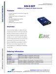
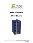
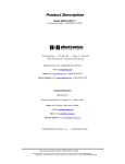
1
User Manual Elinx ESW500Series Managed Din Rail Ethernet Switch ESW500 Series Documentation Number: ESW500series-0912m International Headquarters: 707 Dayton Road Ottawa, IL 61350 USA Phone (815) 433-5100 Website: www.bb-elec.com Sales e-mail: [email protected] Technical Support: [email protected] – European Headquarters B&B Electronics Westlink Commercial Park Oranmore, Co. Galway, Ireland Phone +353 91-792444 Website: www.bb-europe.com Sales e-mail: [email protected] Technical Support: [email protected] Original – March 2011 ©2011 No part of this publication may be reproduced or transmitted in any form or by any means, electronic or mechanical, including photography, recording, or any information storage and retrieval system without written consent. Information in this manual is subject to change without notice, and does not represent a commitment on the part. B&B Electronics Manufacturing shall not be liable for incidental or consequential damages resulting from the furnishing, performance, or use of this manual. All brand names used in this manual are the registered trademarks of their respective owners. The use of trademarks or other designations in this publication is forreference purposes only and does not constitute an endorsement by the trademark holder. This document was created using Author-it, Microsoft Word, Adobe Acrobat, Snag It and other software. Table of Contents Table of Contents Chapter 1 – Introduction 1 OVERVIEW ........................................................................................................................ 1 FEATURES ......................................................................................................................... 1 PACKAGE CHECK LIST ........................................................................................................... 1 ESW508 SERIES - FRONT PANE .............................................................................................. 2 BOTTOM VIEW.................................................................................................................... 2 ESWG510 SERIES - FRONT PANEL .......................................................................................... 3 BOTTOM VIEW.................................................................................................................... 3 ESW516 SERIES - FRONT PANEL............................................................................................. 4 BOTTOM VIEW.................................................................................................................... 4 LED DESCRIPTION .............................................................................................................. 5 MOUNTING OPTIONS ............................................................................................................ 6 Dimensional Drawing 6 ESW508 SERIES................................................................................................................ 6 ESWG510 SERIES ............................................................................................................. 7 ESW516 ......................................................................................................................... 7 DC POWER CONNECTIONS ..................................................................................................... 8 FAULT RELAY ..................................................................................................................... 8 GIGABIT COMBO PORTS ........................................................................................................ 8 DEFAULT SETTINGS.............................................................................................................. 8 Console Port (DB9 Male) ................................................................................................ 8 Serial Cable Pin out ....................................................................................................... 8 Network Settings .......................................................................................................... 9 Default Security ........................................................................................................... 9 ETHERNET PORT CONFIGURATIONS ........................................................................................... 9 Chapter 2 – Initial Setup / Configuration 10 TELNET MODE .................................................................................................................. 10 CONSOLE MODE ............................................................................................................... 10 Navigating Console Mode ............................................................................................. 11 OVERVIEW ...................................................................................................................... 11 IP SETTINGS ................................................................................................................... 12 DHCP Setup ............................................................................................................... 12 Static IP Address Setup ............................................................................................... 12 FACTORY DEFAULT ............................................................................................................. 13 LOGOUT ......................................................................................................................... 13 Chapter 3 – Web Browser Configuration 14 WEB SERVER ACCESS ......................................................................................................... 14 BASIC SETTINGS ............................................................................................................... 15 SYSTEM INFORMATION ........................................................................................................ 15 PASSWORD SETTINGS ......................................................................................................... 15 ACCESABLE IP.................................................................................................................. 15 PORT ............................................................................................................................ 16 IP SETTING ..................................................................................................................... 16 TIME SETTING .................................................................................................................. 17 Chapter 4 – Advanced Settings 18 RINGON ......................................................................................................................... 18 Single RingOn configuration ......................................................................................... 18 Dual RingOn Configuration ........................................................................................... 19 Status and Port State definition .................................................................................... 19 RAPID SPANNING TREE PROTOCOL (RSTP) ............................................................................... 20 RSTP Setup ................................................................................................................ 20 RSPT Information ....................................................................................................... 20 Port Configuration ....................................................................................................... 21 VLAN (VIRTUAL LAN)........................................................................................................ 22 Port VLAN Setup ......................................................................................................... 22 802.1Q VLAN Setup .................................................................................................... 22 TRUNKING ...................................................................................................................... 24 QOS (QUALITY OF SERVICE)................................................................................................. 24 QoS Setup ................................................................................................................. 24 Port Priority ............................................................................................................. 25 IGMP SNOOPING (INTERNET GROUP MANAGEMENT PROTOCOL) ....................................................... 27 BROADCAST STORM PROTECTION ........................................................................................... 28 BANDWIDTH .................................................................................................................... 29 PORT MIRRORING .............................................................................................................. 30 STATIC MAC ADDRESS FORWARDING CONFIGURATION.................................................................. 30 Table configuration: .................................................................................................... 30 Chapter 5 – Administration 32 SNMP ........................................................................................................................... 32 DIAGNOSTICS .................................................................................................................. 32 SCAN NETWORK ............................................................................................................... 32 PING TEST ...................................................................................................................... 33 EMAIL WARNING ............................................................................................................... 34 Relay Warning ............................................................................................................ 34 PERFORMANCE MONITOR ..................................................................................................... 35 MAC ADDRESS TABLE ........................................................................................................ 35 Log Information .......................................................................................................... 36 SYSTEM UPDATE ............................................................................................................... 37 Firmware Update ........................................................................................................ 37 Backup Settings ......................................................................................................... 38 SFP MODULES ................................................................................................................. 39 SPECIFICATION................................................................................................................. 39 Chapter 1 – Introduction Overview B&B Electronics Elinx family of Managed Industrial Din Rail mount Ethernet switches have been designed to meet light Industrial and commercial communication requirements. The ESW500 Managed Series offers a variety of Industrial models. The switch configurations range from 8 ports to 16 ports with all RJ45 copper to RJ45 copper with multi mode, single mode, and or SFP gigabit ports. Two ports can be used for network redundancy by implementing our RingOn technology. RingOn has been developed to provide a rapid recovery system for Industrial networks. If any part of the ring disconnects, network communications will automatically be restored by RingOn technology. All RJ45 copper ports support auto-negotiation, 10/100Mbps or 10/100/1000Mbps data rate, full/half duplex, flow control and auto-MDI/MDIX. The Elinx switches provide advanced management functions such as: RingOnTM, VLAN, Trunking, QoS (Quality of Service), IGMP Snooping, Port Rate Control, Port Mirroring, Static Mac Address Forwarding Table, SNMP (Simple Network Management Protocol), Diagnosis, Email/Relay fault warning and field Firmware Update. Features Light Industrial and Commercial 61000-6-1 specifications -10 to 60°C or -40 to 75°C (-T models) temperature rating Supports IEEE 802.3 10Base-T,802.3u 100Base-TX IEEE 802.3z for 1000BaseSX/LX/LHX/ZX RJ-45 port supports auto MDI/MDI-X function SC Single mode and Multi mode fiber connectors Gigabit options with copper and SFP combo ports Web Browser Management and Configuration RingOn redundant rapid recovery system Rapid Spanning Tree Protocol recover system IGMP with Query mode for multimedia application Port based VLAN / 802.1 Q Tag VLAN Relay alarm output for system events Port mirroring for diagnostics 256K bytes packet buffer 8k MAC address table 12 to 36 VDC power input (All Models) 10 to 24 VAC (ESW508, ESW516 Models) Din Rail and Panel Mount 100% burn in testing 5 year warranty Package Check List B&B Managed Switch Din rail and panel mounting Serial cable for console port Installation Guide CD-with User’s Manual Manual Documentation Number: ESW500series-0912m B&B Electronics Mfg Co Inc – 707 Dayton Rd - PO Box 1040 - Ottawa IL 61350 - Ph 815-433-5100 - Fax 815-433-5104 – www.bb-elec.com B&B Electronics – Westlink Commercial Park – Oranmore, Galway, Ireland – Ph +353 91-792444 – Fax +353 91-792445 – www.bb-europe.com 1 ESW508 Series - Front Pane Bottom View 1. System Ready 2. Redundant Power LED 3. 10/100BaseT(X) RJ45 Ports 4. Link LED 5. Speed LED 6. 100BaseFX, SC Fiber Port 7. Fiber Link, Activity LED 8. Console Port 9. Fault Relay 10. Ground Screw 11. Input Power Terminal Block 2 Manual Documentation Number: ESW500series-0912m B&B Electronics Mfg Co Inc – 707 Dayton Rd - PO Box 1040 - Ottawa IL 61350 - Ph 815-433-5100 - Fax 815-433-5104 – www.bb-elec.com B&B Electronics – Westlink Commercial Park – Oranmore, Galway, Ireland – Ph +353 91-792444 – Fax +353 91-792445 – www.bb-europe.com ESWG510 Series - Front Panel Bottom View 1. System Ready 2. Power LED 3. 10/100BaseT(X) RJ45 Ports 4. Speed LED 5. Link LED 6. Fiber Link, Activity LED 7. 100BaseFX, SC Fiber Port 8. Input Power Terminal Block 9. Ground Screw 10. Console Port 11. Combo RJ45 or SFP Port 12. Fault Relay Manual Documentation Number: ESW500series-0912m B&B Electronics Mfg Co Inc – 707 Dayton Rd - PO Box 1040 - Ottawa IL 61350 - Ph 815-433-5100 - Fax 815-433-5104 – www.bb-elec.com B&B Electronics – Westlink Commercial Park – Oranmore, Galway, Ireland – Ph +353 91-792444 – Fax +353 91-792445 – www.bb-europe.com 3 ESW516 Series - Front Panel Bottom View 1. Console Port 2. System Ready 3. Power LED 4. 10/100BaseT(X) RJ45 Ports 5. Link LED 6. Speed LED 7. Fiber Link, Activity LED 8. 100BaseFX, SC Fiber Port 9. Fault Relay 10. Ground Screw 11. Input Power Terminal Block 4 Manual Documentation Number: ESW500series-0912m B&B Electronics Mfg Co Inc – 707 Dayton Rd - PO Box 1040 - Ottawa IL 61350 - Ph 815-433-5100 - Fax 815-433-5104 – www.bb-elec.com B&B Electronics – Westlink Commercial Park – Oranmore, Galway, Ireland – Ph +353 91-792444 – Fax +353 91-792445 – www.bb-europe.com LED Description LED PWR STA 10/100 Copper SPD LED 10/100 Copper LNK LED Fiber LED Combo Port 10/100/1000 Copper SPD LED Combo Port 10/100/1000 Copper LNK LED SFP Port LED Status Green Off Green Off Green Off Green Blinking Off Green Blinking Off Green Off Green Blinking Off Green Blinking Off Description Power Applied No power System Ready System down 100Mbps 10Mbps Link Activity Not connected Link Activity Not connected 1000Mbps 10/100Mbps Link Activity Not connected 1000Mbps Activity Not connected to network to network to network to network Manual Documentation Number: ESW500series-0912m B&B Electronics Mfg Co Inc – 707 Dayton Rd - PO Box 1040 - Ottawa IL 61350 - Ph 815-433-5100 - Fax 815-433-5104 – www.bb-elec.com B&B Electronics – Westlink Commercial Park – Oranmore, Galway, Ireland – Ph +353 91-792444 – Fax +353 91-792445 – www.bb-europe.com 5 Mounting Options Dimensional Drawing ESW508 Series 6 Manual Documentation Number: ESW500series-0912m B&B Electronics Mfg Co Inc – 707 Dayton Rd - PO Box 1040 - Ottawa IL 61350 - Ph 815-433-5100 - Fax 815-433-5104 – www.bb-elec.com B&B Electronics – Westlink Commercial Park – Oranmore, Galway, Ireland – Ph +353 91-792444 – Fax +353 91-792445 – www.bb-europe.com ESWG510 Series ESW516 Manual Documentation Number: ESW500series-0912m B&B Electronics Mfg Co Inc – 707 Dayton Rd - PO Box 1040 - Ottawa IL 61350 - Ph 815-433-5100 - Fax 815-433-5104 – www.bb-elec.com B&B Electronics – Westlink Commercial Park – Oranmore, Galway, Ireland – Ph +353 91-792444 – Fax +353 91-792445 – www.bb-europe.com 7 DC / AC Power Connections ESW508 / ESW516 Series ESW510 Series Fault Relay Relay (Normally Open) Gigabit Combo Ports Default Settings Console Port (DB9 Male) Serial baud rate: 115200 Data Bits: 8 Parity: NONE Stop bits: 1 Flow Control: NONE Serial Cable Pin out PC Serial Port DB 9 5 3 2 8 Console Port DB9 1 3 4 Manual Documentation Number: ESW500series-0912m B&B Electronics Mfg Co Inc – 707 Dayton Rd - PO Box 1040 - Ottawa IL 61350 - Ph 815-433-5100 - Fax 815-433-5104 – www.bb-elec.com B&B Electronics – Westlink Commercial Park – Oranmore, Galway, Ireland – Ph +353 91-792444 – Fax +353 91-792445 – www.bb-europe.com Network Settings IP address: 192.168.118.100 Subnet Mask: 255.255.255.0 Gateway: 192.168.118.1 Default Security User Name: admin Password: admin VLAN All Ports are members of VLAN 1 (management VLAN) Ethernet Port Configurations RJ45 Copper Ports: Half Duplex Full Duplex Auto Negotiation 100Base Fiber Ports: Full Duplex 1000Base Copper/Fiber Ports: Full Duplex Manual Documentation Number: ESW500series-0912m B&B Electronics Mfg Co Inc – 707 Dayton Rd - PO Box 1040 - Ottawa IL 61350 - Ph 815-433-5100 - Fax 815-433-5104 – www.bb-elec.com B&B Electronics – Westlink Commercial Park – Oranmore, Galway, Ireland – Ph +353 91-792444 – Fax +353 91-792445 – www.bb-europe.com 9 Chapter 2 – Initial Setup / Configuration The following information will explain how to access the unit for the first time. There are three ways to configure the IP address setting, console mode, telnet, and a web browser. Telnet Mode Before the Managed switch is installed the Telnet Mode feature can be used to enter network settings. To open a telnet session select the Start button then either open the Command window by selecting the icon or in some operating systems the Run command line can be used to open the Command window by typing cmd and selecting enter. Once the window is opened type telnet then the IP address of the unit as shown below. Default IP address is 192.168.118.100. Select enter and the User Login screen will open. Once the login screen opens follow the instructions listed under the Console mode section on the following page. Console Mode Before the Managed switch is installed on a LAN the Console Mode feature can be used to change the network settings from the defaults. Console Mode, allows the configuration of the Managed switch network settings (using an RS-232 connection through the RS232 Console port of the switch) from a PC running a VT100 terminal emulation program such as HyperTerminal. When the serial connection is made and HyperTerminal has opened the Console Mode screen will appear in the program window. The serial port settings must be 8-N-1 at 115200 baud. If Console screen does not appear select Enter. NOTE: 1. Supplied RS-232 cable must be used. Straight through or cross over will not work. 2. If Console screen does not appear select Enter. 10 Manual Documentation Number: ESW500series-0912m B&B Electronics Mfg Co Inc – 707 Dayton Rd - PO Box 1040 - Ottawa IL 61350 - Ph 815-433-5100 - Fax 815-433-5104 – www.bb-elec.com B&B Electronics – Westlink Commercial Park – Oranmore, Galway, Ireland – Ph +353 91-792444 – Fax +353 91-792445 – www.bb-europe.com 1. Using a VT100 Terminal emulation program (typically HyperTerminal in Windows) open the computer COM port connected to the switch (using supplied RS-232 cable). 2. In the HyperTerminal Port Settings window set: HyperTerminal configuration: Serial baud rate: 115200 Data Bits: 8 Parity: NONE Stop bits: 1 Flow Control: NONE 3. If Console screen does not appear select Enter. Navigating Console Mode The Console Login Screen will appear prompting the user for User Name and Password. Default settings: User Name: admin Password: admin The Console mode screen has 4 configuration options. 1. Overview 2. IP Settings 3. Factory Default 4. Logout Overview The Overview page displays the current switch IP address, MAC address, Firmware version, configured name, location, and description. Select Enter to view information Select Enter to return to main menu Default settings IP address: 192.168.118.100 Subnet Mask: 255.255.255.0 Gateway: 192.168.118.1 Manual Documentation Number: ESW500series-0912m B&B Electronics Mfg Co Inc – 707 Dayton Rd - PO Box 1040 - Ottawa IL 61350 - Ph 815-433-5100 - Fax 815-433-5104 – www.bb-elec.com B&B Electronics – Westlink Commercial Park – Oranmore, Galway, Ireland – Ph +353 91-792444 – Fax +353 91-792445 – www.bb-europe.com 11 IP Settings The IP Settings page allows two methods of network address configuration, DHCP or static. DHCP Setup Use down arrow key to IP Settings / select Enter Select #1: Obtain IP address Automatically (DHCP) / select Enter The confirmation window will open. Select Yes. Static IP Address Setup 12 Use down arrow key to IP Settings / select Enter Select #2: Use the following IP Address (Fixed IP) select Enter Add IP address, Subnet Mask, Default Gateway. The confirmation window will open. Select Yes. Manual Documentation Number: ESW500series-0912m B&B Electronics Mfg Co Inc – 707 Dayton Rd - PO Box 1040 - Ottawa IL 61350 - Ph 815-433-5100 - Fax 815-433-5104 – www.bb-elec.com B&B Electronics – Westlink Commercial Park – Oranmore, Galway, Ireland – Ph +353 91-792444 – Fax +353 91-792445 – www.bb-europe.com Factory Default The Factory Default page allows the managed switch to be set back to default settings. This will include the user name, password, and network settings. Logout When finished with viewing and configuring the settings in Console Mode arrow down to the Logout page and select Yes. Manual Documentation Number: ESW500series-0912m B&B Electronics Mfg Co Inc – 707 Dayton Rd - PO Box 1040 - Ottawa IL 61350 - Ph 815-433-5100 - Fax 815-433-5104 – www.bb-elec.com B&B Electronics – Westlink Commercial Park – Oranmore, Galway, Ireland – Ph +353 91-792444 – Fax +353 91-792445 – www.bb-europe.com 13 Chapter 3 – Web Browser Configuration The Web Server provides a convenient way to configure the managed switch from web browser software (such as Internet Explorer). To use the web server management and monitoring functions from a host PC connected to the same LAN they must be configured with the appropriate network settings. Web Server Access Two web servers types are supported, HTTP and HTTPS. Open the web browser and enter the IP address of the managed switch. (MS Internet Explorer and Firefox supported) The security login window will open requesting login user name and pass word. Default: User Name: admin Password: admin The home page will now open displaying the Overview page. The left column will display a list of configurable options. At the top right the Help button is available to assist in configuration. At the right an overview of page function is available. 14 Manual Documentation Number: ESW500series-0912m B&B Electronics Mfg Co Inc – 707 Dayton Rd - PO Box 1040 - Ottawa IL 61350 - Ph 815-433-5100 - Fax 815-433-5104 – www.bb-elec.com B&B Electronics – Westlink Commercial Park – Oranmore, Galway, Ireland – Ph +353 91-792444 – Fax +353 91-792445 – www.bb-europe.com Basic Settings System Information The System Information Page allows the user to assign a unique name, location of the switch, type of function, and contact name which will assist in developing a network layout. The information will also be available in SNMP. Each setting in the System Info Settings page allows a maximum length of 64 characters. Password Settings The Password Settings page allows up to 3 users to assign unique Users Names and Passwords. The User Index is used to select the individual users. The maximum number of characters is 32 and a blank password can be configured. If a blank password is used the log file will not trace the login of this user. Accesable IP Two web server types are available, HTTP and HTTPS. When Access Control is enabled, access to the managed switch web server is limited to the IP address listed on this page. Connections from clients with other IP addresses will be refused. Manual Documentation Number: ESW500series-0912m B&B Electronics Mfg Co Inc – 707 Dayton Rd - PO Box 1040 - Ottawa IL 61350 - Ph 815-433-5100 - Fax 815-433-5104 – www.bb-elec.com B&B Electronics – Westlink Commercial Park – Oranmore, Galway, Ireland – Ph +353 91-792444 – Fax +353 91-792445 – www.bb-europe.com 15 The web server connection, HTTP (Hypertext Transfer Protocol), is a communications protocol used to transfer or convey information on the World Wide Web using default port 80. Https is a URL that implements a Secure HTTP connection using default port 443. All entered access IP Addresses must be a legal IP address. Accessible IP addresses cannot be broadcast address or net mask (for example: 255.255.255.0). Each switch is allowed up to ten accessible IP addresses. When this feature is enabled at least one of these IP addresses must be in the same subnet and a member of VLAN 1 for management changes. By default all ports are members of VLAN 1. Port Each port can be individually configured to meet communication requirements using Mode, Flow Control, and MDI/MDIX. Setting Media Type Description The type of media, copper or fibber The transmit speed between two Mode nodes Managing data transmission Flow Control between two Nodes Medium dependent interface of MDI/MDIX nodes Enable Enable port configuration options Default value Copper or Fiber Auto-Negotiation Enable Auto MDI/MDIX Disable IP Setting There are two options that can be used to configure the network settings of the Ethernet managed switch, DHCP and Fixed (Static) IP Address. DHCP will allow a DHCP server to automatically assign an IP Address setting. The Fixed (Static) IP Address setting allows the user to manually configure the IP Address, Subnet Mask, and Gateway settings. 16 Manual Documentation Number: ESW500series-0912m B&B Electronics Mfg Co Inc – 707 Dayton Rd - PO Box 1040 - Ottawa IL 61350 - Ph 815-433-5100 - Fax 815-433-5104 – www.bb-elec.com B&B Electronics – Westlink Commercial Park – Oranmore, Galway, Ireland – Ph +353 91-792444 – Fax +353 91-792445 – www.bb-europe.com Setting Description DHCP/Fixed IP Network configuration The unique IP Address of the IP Address switch The range of logical addresses Subnet Mask within the address space Default The node that serves as an Gateway entrance to another network DNS Domain Name System (DNS) Default value Fixed (Static) IP 192.168.118.100 255.255.255.0 192.168.118.1 blank Note: Incorrect Subnet Mask configuration may cause erratic RingOn functionality. Time Setting Time Settings allows the user to select the appropriate Time Zone for his location. The NTC (Network Time Protocol) synchronizes the clocks of computer systems over packet-switched, variable-latency data networks. NTP uses UDP port 123 as its transport layer. It is designed particularly to resist the effects of variable latency. Setting Local Time/NTP Time Zone DST Date Time Description Time setting for switch system a region of the Earth Daylight saving time The format must be yyyy-mm-dd The format must be hh:mm:ss Default value Local Time GMT-6 Disable 2011-01-01 00:00:00 Manual Documentation Number: ESW500series-0912m B&B Electronics Mfg Co Inc – 707 Dayton Rd - PO Box 1040 - Ottawa IL 61350 - Ph 815-433-5100 - Fax 815-433-5104 – www.bb-elec.com B&B Electronics – Westlink Commercial Park – Oranmore, Galway, Ireland – Ph +353 91-792444 – Fax +353 91-792445 – www.bb-europe.com 17 Chapter 4 – Advanced Settings RingOn RingOn is Rapid Rescue and Recovery System for Ethernet networks which is designed to provide a backup system (path) for communications. RingOn uses two ports on each switch to form a ring with the switch automatically selecting an active port and a blocked port. If a break occurs in the active line the RingOn recovery system will automatically switch ports, enable the blocked port, and continue to communications. A break in the ring network will also activate the Fault Relay warning the administrator of the problem. The recovery time in the event of a break is less than 15 ms. Two types of RingOn configurations are available: single loop and dual loop. Dual loop configurations connect two or more single loops. When configuring dual rings unique ID’s are used for each ring. Single RingOn configuration Single Ring The web configuration screen shot illustrates the steps needed to implement a single ring. In this case the switch is automatically configured as Master. Port 1 used for communications and Port 2 blocked. Only the master will display a Port Status of Blocked port. 18 Manual Documentation Number: ESW500series-0912m B&B Electronics Mfg Co Inc – 707 Dayton Rd - PO Box 1040 - Ottawa IL 61350 - Ph 815-433-5100 - Fax 815-433-5104 – www.bb-elec.com B&B Electronics – Westlink Commercial Park – Oranmore, Galway, Ireland – Ph +353 91-792444 – Fax +353 91-792445 – www.bb-europe.com Dual RingOn Configuration Two types of RingOn configurations are available: single loop and dual loop. Dual loop configurations connect two or more single loops. When configuring dual rings, unique ID’s are used for each ring. The following diagram is the typical dual loop illustration. Dual Ring The web configuration screen shot illustrates the steps needed to implement a dual ring. Both ID 1 and 2 are enabled. Ports 1 and 2 connect single rings. Ports 3 and 4 connect the single rings together. Both rings are connected together using ID 4 coupling port. Once ports are connected and configuration saved the Status displays Complete. M S Status and Port State definition Status Not Applied Complete Complete Incomplete P1 P1 P1 P1 Port Fwd, Fwd, Fwd, Fwd, State P2 Fwd P2 Block P2 Fwd P2 Down P 2 Down RingOn not enabled RingOn Master Ring Slave P 2 RJ45 link broken P 2 not connected to RingOn port Manual Documentation Number: ESW500series-0912m B&B Electronics Mfg Co Inc – 707 Dayton Rd - PO Box 1040 - Ottawa IL 61350 - Ph 815-433-5100 - Fax 815-433-5104 – www.bb-elec.com B&B Electronics – Westlink Commercial Park – Oranmore, Galway, Ireland – Ph +353 91-792444 – Fax +353 91-792445 – www.bb-europe.com 19 Rapid Spanning Tree Protocol (RSTP) The Rapid Spanning Tree Protocol (RSTP) has evolved from the Spanning Tree Protocol (STP) to provide faster spanning tree convergence after a topology change. Rapid Spanning Tree Protocol will assist in network link failures by including spare (redundant) links to provide automatic backup paths. Another basic function of RSTP is to prevent unintended loops and protect against broadcast storms. RSTP Setup RSTP Configuration Screen Redundancy Setting: RSTP Bridge Priority: (o – 61440) Switches configured with the lowest numerical value have the highest priority and will operate as the root. The value can be changed using multiples of 4096. Once the change is completed the switch must be rebooted. Hello Time: (1-10): Determines the frequency BPDU (Bridge Protocol Data Units) packets are transmitted. BPDU packets are used to check RSTP current status. (Health of RSTP configuration) Forwarding Delay: (4-30) Number of seconds the port waits before changing from its Rapid Spanning-Tree Protocol learning and listening states to the forwarding state. Max Age Time:(6-40) Number of seconds the switch waits without receiving Spanningtree Protocol configuration messages before attempting a reconfiguration RSPT Information Root Bridge: Displays spanning tree Root Bridge information. Root Bridge Information 20 Manual Documentation Number: ESW500series-0912m B&B Electronics Mfg Co Inc – 707 Dayton Rd - PO Box 1040 - Ottawa IL 61350 - Ph 815-433-5100 - Fax 815-433-5104 – www.bb-elec.com B&B Electronics – Westlink Commercial Park – Oranmore, Galway, Ireland – Ph +353 91-792444 – Fax +353 91-792445 – www.bb-europe.com Port Information Port Information Port Configuration Priority: (0 – 240) A method of prioritizing how ports are blocked. The value is configured in multiples of 16 with the highest value being blocked. Port Cost: (1 – 200,000,000) RSTP method of ensuring that optimal paths will be selected after a link failure. The paths are between a transmitting bridge to a receiving bridge. Admin P2P: Some rapid state transactions used within RSTP are dependent upon whether the port concerned can only be connected to exactly one point to point bridge or can be connected to two or more bridges. This function allows the P2P status of the link to be manipulated administratively. o o P2P True – Enabled P2P False - Disabled Admin Edge: Used to define ports as end stations which prevent bridging loops in the network. o True - configures it as an End port Admin Non Stp: The port includes the STP mathematic calculation. True is not including STP mathematic calculation, false is including the STP mathematic calculation. Port Configuration Manual Documentation Number: ESW500series-0912m B&B Electronics Mfg Co Inc – 707 Dayton Rd - PO Box 1040 - Ottawa IL 61350 - Ph 815-433-5100 - Fax 815-433-5104 – www.bb-elec.com B&B Electronics – Westlink Commercial Park – Oranmore, Galway, Ireland – Ph +353 91-792444 – Fax +353 91-792445 – www.bb-europe.com 21 VLAN (Virtual LAN) A Virtual LAN, commonly known as a VLAN are used to creating independent logical networks within a physical network. Several VLANs may co-exist within such a network. VLAN’s help in reducing the broadcast domain and aids network administrators by separating logical segments of a LAN that should not exchange data. B&B Electronics Managed switches support port-based VLAN and 802.1Q VLAN. Port VLAN Setup The default Virtual LAN is VLAN 1 which all ports are members. VLAN 1 operates as the management VLAN meaning at least one port must be a member of VLAN 1 to access and manage the switch. VLAN 1 also allows the switch to operate as a standard switch. Every port must belong to a VLAN and ports may belong to more than one VLAN ID. B&B Electronics Managed switches will support up to 26 port based VLAN groups. 802.1Q VLAN Setup B&B Electronics Managed switches also support IEEE 802.1q VLAN. Implemented 802.1q VLANs can extend over multiple switches. Switches can be from different manufactures as long as they support 802.1q A typical 802.1Q VLAN network and the web server configuration page can be found below. Keep in mind while looking at the diagram the difference between VLAN ID (frames that are tagged) and PVID (frame that are untagged). The configuration page displays the default PVID value for 802.1Q VLAN. Each port can be configured to filer (remove) the 802.1Q tag or pass the 802.1Q tag to the connected device. Tag Filter Setting: Untagged - 802.1Q tag removed Tagged - 802.1Q tag passed on. If the tag is not present an 802.1Q tag will be added. The illustration below shows an example of when the Tag Filter is configured for both untagged and tagged port settings. Most PC’s would be connected to a switch port that was configured for Untag. The two ports connecting the switches together are uplink ports and should be setup as Tag ports. 22 Manual Documentation Number: ESW500series-0912m B&B Electronics Mfg Co Inc – 707 Dayton Rd - PO Box 1040 - Ottawa IL 61350 - Ph 815-433-5100 - Fax 815-433-5104 – www.bb-elec.com B&B Electronics – Westlink Commercial Park – Oranmore, Galway, Ireland – Ph +353 91-792444 – Fax +353 91-792445 – www.bb-europe.com Manual Documentation Number: ESW500series-0912m B&B Electronics Mfg Co Inc – 707 Dayton Rd - PO Box 1040 - Ottawa IL 61350 - Ph 815-433-5100 - Fax 815-433-5104 – www.bb-elec.com B&B Electronics – Westlink Commercial Park – Oranmore, Galway, Ireland – Ph +353 91-792444 – Fax +353 91-792445 – www.bb-europe.com 23 Trunking Trunking sometimes called Link aggregation is a method of paralleling more multiple ports between two switches. The ability to configure this type of connection will increase the speed beyond the limits of a single port. The multiple links between switches can also act as a redundant path if one port losses communication. Limitations: Port 1 cannot be part of a Trunking group Ports are not allowed to become members of multiple Trunking groups. QoS (Quality of Service) Quality of Service is a method of prioritizing Ethernet applications or device communications on a LAN. Once a packet is received by the switch it can take persistence over other packets being received thus reducing latency and establishing a reliable method of data delivery. Service quality features 4 different levels of queue, (high, middle, normal, low). High- priority data packet stays in the switch for a short time. The data packets are assigned priority levels in accordance to 802.1 priority tag and DiffServ priority tag settings. QoS full wire-speed mechanism can be configured using the relative priority and absolute priority. QoS Setup QoS 24 Enable - all QoS options become available. o Port Priority o 802.1 Priority 802.1 Priority Settings o DiffServ Priority DSCP Priority Settings o High Queue Preemptive Mode Manual Documentation Number: ESW500series-0912m B&B Electronics Mfg Co Inc – 707 Dayton Rd - PO Box 1040 - Ottawa IL 61350 - Ph 815-433-5100 - Fax 815-433-5104 – www.bb-elec.com B&B Electronics – Westlink Commercial Park – Oranmore, Galway, Ireland – Ph +353 91-792444 – Fax +353 91-792445 – www.bb-europe.com Port Priority Two settings are available, Normal and High. When set to high packets have the lowest latency. 802.1p Priority The 802.1p header includes a three-bit field for prioritization, which allows packets to be grouped into various traffic classes. 802.1p traffic is simply classified and sent to the destination. Choose Enable to start priority features based on 802.1p for each port. 802.1p Priority Settings After selecting the 802.1p Priority Settings button the 802.1q Priority List window opens. 802.1p establishes eight levels of priority. The highest priority is seven, used for network critical traffic, five and six used for delay-sensitive applications, four through one used in controlled data applications (streaming data). The zero value is used as default (no other setting is uses). 802.1p priority setting, assign tag of 0-7 (High, Middle, Low, Lowest) to each queue. Manual Documentation Number: ESW500series-0912m B&B Electronics Mfg Co Inc – 707 Dayton Rd - PO Box 1040 - Ottawa IL 61350 - Ph 815-433-5100 - Fax 815-433-5104 – www.bb-elec.com B&B Electronics – Westlink Commercial Park – Oranmore, Galway, Ireland – Ph +353 91-792444 – Fax +353 91-792445 – www.bb-europe.com 25 DiffServ Priority DiffServ or Differentiated Services is a computer networking architecture that specifies scalable and coarse-grained mechanism for classifying, managing network traffic and providing quality of service (QoS) guarantees on modern IP networks. DiffServ can, for example, be used to provide low-latency, guaranteed service (GS) to critical network traffic such as voice or video while providing simple best-effort traffic guarantees to non-critical services such as web traffic or file transfers. The Managed switch can classify traffic based on the DSCP field in the IP Header. DSCP in both IPv4 and IPv6 will be supported. If DSCP priority is enabled, the switch classifies traffic based on the DSCP value. DiffServ is a Layer 3 marking scheme that uses the DiffServ Code Point (DSCP) field in the IP header to store the packet priority information. DSCP is an advanced intelligent method of traffic marking as you can choose how your network prioritizes different types of traffic. DSCP uses 64 values that map to user-defined service levels, allowing you to establish more control over network traffic. Choose Enable to start priority features based on DiffServ. Then select the DSCP Priority Settings button. DSCP Priority Settings (Differentiated Services Code Point) An advantage of DiffServ allows the administrator to configure how selected applications and types of traffic are handled by assigning various grades of network service to them. DSCP uses the IP header of a packet and therefore priority is preserved across the Internet. DSCP is backward compatible with IPV4 TOS, which allows operation with existing devices that use a layer 3 TOS enabled prioritization scheme. Once DiffServ Priority is selected, open the DSCP Priority Settings which will allow a value (0-63) to be assigned to different queues. 26 Manual Documentation Number: ESW500series-0912m B&B Electronics Mfg Co Inc – 707 Dayton Rd - PO Box 1040 - Ottawa IL 61350 - Ph 815-433-5100 - Fax 815-433-5104 – www.bb-elec.com B&B Electronics – Westlink Commercial Park – Oranmore, Galway, Ireland – Ph +353 91-792444 – Fax +353 91-792445 – www.bb-europe.com Setting QoS enable Port-based QoS enable 802.1p QoS enable 802.1p QoS Settings DiffServ QoS enable DiffServ QoS Settings Port priority Description Enable QoS function Enable Port-based QoS function Enable 802.1p QoS function Configure 802.1p priority Enable DiffServ QoS function Configure DiffServ priority Configure port priority Default value Disable Enable this group Disable ---Disable ---High IGMP Snooping (Internet Group Management Protocol) IGMP Snooping provides a way to route multicast traffic and reduce unwanted traffic. IP multicasting is commonly used when sending the same information to many receivers. IGMP routes the multicast traffic to the correct devices and will not broadcast the message to unintended devices. IP multicast addresses are in the range of 224.0.0.0 through 239.255.255.255. Enabling IGMP allows the ports to detect IGMP queries, report packets, and manage IP multicast traffic through the switch. IGMP have three fundamental types of message shown as follows: Query A message sent from the querier (IGMP router or switch) asking for a response from each host belonging to the multicast group. Report A message sent by a host to the querier to indicate that the host wants to be or is a member of a given group indicated in the report message. Manual Documentation Number: ESW500series-0912m B&B Electronics Mfg Co Inc – 707 Dayton Rd - PO Box 1040 - Ottawa IL 61350 - Ph 815-433-5100 - Fax 815-433-5104 – www.bb-elec.com B&B Electronics – Westlink Commercial Park – Oranmore, Galway, Ireland – Ph +353 91-792444 – Fax +353 91-792445 – www.bb-europe.com 27 Leave Group A message sent by a host to the querier to indicate that the host has quit being a member of a specific multicast group. IGMP snooping has been expanded, overcoming some limitation of old versions. It works with GMRP by sending GMRP notifications when PC’s change port. This will avoid multicast traffic lose. Query Interval Query interval time (125-5000 seconds) between IGMP Query transmitions. Multicast Age Time The length of the MAC address will remain in the multicast table. The switch will delete this group and send leave message. Broadcast Storm Protection Broadcast storm protection prevents network problems due to accidental network redundant loops reproducing broadcasts and multicasts. Without this type of control the packets are received by all switches on the network and transmitted out all ports. Max Bit Rate is the bit rate setting which can be adjusted between 65K bps and 90M bps or set to no limit. The storm protection feature will also allow the administrator to select the types of packets that are controlled. Destination Lookup Failure is also called DLF Message which means a packet type table does not match the MAC address table, and the message does not belong to broadcast or multi broadcast message. The way the switch handles such DLF message is just the same as it handles the acceptance of broadcast messages. 28 Manual Documentation Number: ESW500series-0912m B&B Electronics Mfg Co Inc – 707 Dayton Rd - PO Box 1040 - Ottawa IL 61350 - Ph 815-433-5100 - Fax 815-433-5104 – www.bb-elec.com B&B Electronics – Westlink Commercial Park – Oranmore, Galway, Ireland – Ph +353 91-792444 – Fax +353 91-792445 – www.bb-europe.com Bandwidth Bandwidth is a rate of data transfer related to channel capacity for communication. Rate limiting is used to control the rate of traffic sent or received on a network interface. Traffic that is less than or equal to the specified rate is sent, whereas traffic that exceeds the rate is dropped or delayed. Rate limiting is performed by policing (discarding excess packets), queuing (delaying packets in transit) or congestion control (manipulating the protocol's congestion mechanism). Policing and queuing can be applied to any network protocol. Congestion control can only be applied to protocols with congestion control mechanisms, such as the Transmission Control Protocol (TCP). Note: 1. Switch monitor all type packets and not limited decreases overall latency. 2. Switch will drop packets at limited rate when flow control is disabled. Manual Documentation Number: ESW500series-0912m B&B Electronics Mfg Co Inc – 707 Dayton Rd - PO Box 1040 - Ottawa IL 61350 - Ph 815-433-5100 - Fax 815-433-5104 – www.bb-elec.com B&B Electronics – Westlink Commercial Park – Oranmore, Galway, Ireland – Ph +353 91-792444 – Fax +353 91-792445 – www.bb-europe.com 29 Port Mirroring Port mirroring is used on a network switches to monitor the network traffic of a specific port. The selected port’s Ethernet traffic is duplicated and sent out a 2nd specified port. This is commonly used with network monitoring hardware or software. From Port: This is the source port, data that is to be copied and monitored. To Port: This is the destination port; data is received from source port and analyzed. Data: Each port being monitored will transmit and receive data. During port mirroring the ingress data, egress data, or both can be mirrored to the selected port. Note: 1. Port mirroring will disable IGMP snooping. 2. Port mirroring will reduce the switch performance. Static MAC Address Forwarding Configuration The MAC address forwarding table will not only hold learned addresses, but also up to 10 static unicast or 10 static multicast addresses. Static addresses perform as learned addresses, but are not subject to the aging process. A normal or high priority can also be applied to messages containing the entered MAC address. The action field can be toggled between "Add" and "Delete". The "Static MAC Address" field requires a valid input from the user; it is not case sensitive. When invalid addresses are entered the switch will display a warning message. Table configuration: 30 Select Add new Unicast or Multicast forwarding table Add Static MAC Address to field Select the desired port Select add button Manual Documentation Number: ESW500series-0912m B&B Electronics Mfg Co Inc – 707 Dayton Rd - PO Box 1040 - Ottawa IL 61350 - Ph 815-433-5100 - Fax 815-433-5104 – www.bb-elec.com B&B Electronics – Westlink Commercial Park – Oranmore, Galway, Ireland – Ph +353 91-792444 – Fax +353 91-792445 – www.bb-europe.com Note: 1. 2. 3. 4. Defined MAC addresses assigned port can be modified. Improper static unicast address may cause communication problems. All static addresses can be found in MAC Address Table. Do not add reserved addresses such as GMRP address to the address table. Reserved addresses are often used as managed address. Manual Documentation Number: ESW500series-0912m B&B Electronics Mfg Co Inc – 707 Dayton Rd - PO Box 1040 - Ottawa IL 61350 - Ph 815-433-5100 - Fax 815-433-5104 – www.bb-elec.com B&B Electronics – Westlink Commercial Park – Oranmore, Galway, Ireland – Ph +353 91-792444 – Fax +353 91-792445 – www.bb-europe.com 31 Chapter 5 – Administration SNMP The simple network management protocol (SNMP) is used by network management systems to monitor network attached devices for conditions that warrant administrative attention. The SNMP V1/V2c. SNMP V1, and SNMP V2c use a community string match for authentication, which means that SNMP servers access all objects with read-only or read/write permissions using the community string public/private. It consists of a set of standards for network management, including an application layer protocol, a database schema, and a set of data objects. SNMP exposes management data in the form of variables on the managed systems, which describe the system configuration. These variables can then be queried (and sometimes set) by managing applications. Over TCP/IP, SNMP usually uses UDP ports 161 (SNMP) and 162 (SNMP-traps). SNMP agents reside in network devices where they use MIBs (information specific to the device) to interface the devices with the NMS--which then monitors and controls devices via these agents. An SNMP Trap is a message that is transmitted when a trap event occurs. A valid trap receiver will receive a trap message upon a trap event occurring. RFC1213-MIB supported Cold start trap supported. Diagnostics Scan Network and Ping are two diagnostic tools are provided with your unit. Scan Network will provide a list of active network devices. The Ping function uses the ping command to give users a simple but powerful tool for troubleshooting network problems. Scan Network Scan Network will display IP address, MAC address, and its current status (active or Inactive). 32 Manual Documentation Number: ESW500series-0912m B&B Electronics Mfg Co Inc – 707 Dayton Rd - PO Box 1040 - Ottawa IL 61350 - Ph 815-433-5100 - Fax 815-433-5104 – www.bb-elec.com B&B Electronics – Westlink Commercial Park – Oranmore, Galway, Ireland – Ph +353 91-792444 – Fax +353 91-792445 – www.bb-europe.com Ping Test The Ping function implements the ping command to give users a simple but powerful tool for troubleshooting network problems. The function's most unique feature is the ping command is entered from the user's PC, the actual ping command originates from Managed switch itself. In this way, the user understands the LAN area being tested. To use the Ping function, enter the target IP address, use the default settings or add your desired information then select "Start Test". Once the ping test is started the following results will be displayed. The default settings are: Setting Description Target IP IP address of device Size Size of test (ping) packet Number The number of packet which will be sent Interval The interval time between transmitted ping packets Timeout The no response timeout Note: 1. DNS is not support. Default value blank 60 1 1000 5000 Manual Documentation Number: ESW500series-0912m B&B Electronics Mfg Co Inc – 707 Dayton Rd - PO Box 1040 - Ottawa IL 61350 - Ph 815-433-5100 - Fax 815-433-5104 – www.bb-elec.com B&B Electronics – Westlink Commercial Park – Oranmore, Galway, Ireland – Ph +353 91-792444 – Fax +353 91-792445 – www.bb-europe.com 33 Email Warning The Email Warning function allows e-mail alerts to be sent to defined users when, port link (Up or Down) changes state, Relay Warning is enabled, Broadcast Storm events take place, and every 12 hours. The 12 hour report displays a log file of switch activities. Setting Email Alerts SMTP Server SMTP User SMTP Password Recipient Return Email Address Description IP address which is desired for you The name or IP SMTP Server Account User Name of SMTP Server Account password for this user name Recipient address Default value disable blank blank blank blank blank Once the settings are configured correctly and "Save" is selected a hello email will be sent. 1. Password - "●" not allowed 2. Recipient and "Return Email Address" must be legal email address. Relay Warning The managed switch has a relay output that can be used to signal the occurrence of one or more events when configured by the user. In addition to the events listed on this page the relay can be used to indicate the loss of a link or a Broadcast Storm has occurred. 34 Manual Documentation Number: ESW500series-0912m B&B Electronics Mfg Co Inc – 707 Dayton Rd - PO Box 1040 - Ottawa IL 61350 - Ph 815-433-5100 - Fax 815-433-5104 – www.bb-elec.com B&B Electronics – Westlink Commercial Park – Oranmore, Galway, Ireland – Ph +353 91-792444 – Fax +353 91-792445 – www.bb-europe.com Performance Monitor Performance monitoring is available for each port and displayed on the webpage. The data is captured and will display the total number of events that have occurred since last power cycle. All number will be reset to zero if you reset switch or there is a loss of power. The data will refresh every 30 seconds. MAC Address Table MAC (Media Access Control) address is a hardware address network adapters (NICs) are giving by the manufacturer. The managed switch provides an 8K MAC addresses table with automatic learning and aging. The MAC address table displays this table in an administrator viewable manner. In the address table the MAC addresses can be sorted by specified type. The address list has three sort options, Auto, Port, and by MAC Address. The MAC addresses and the ports to which they are associated with will also be displayed. The STATIC status indicates the entry is controlled by the management CPU and automatic learning Manual Documentation Number: ESW500series-0912m B&B Electronics Mfg Co Inc – 707 Dayton Rd - PO Box 1040 - Ottawa IL 61350 - Ph 815-433-5100 - Fax 815-433-5104 – www.bb-elec.com B&B Electronics – Westlink Commercial Park – Oranmore, Galway, Ireland – Ph +353 91-792444 – Fax +353 91-792445 – www.bb-europe.com 35 and aging of the entry will not take place. In this address table you will find multicast address if you use static multicast forwarding table or IGMP Snooping. Log Information The Log Info page will display the Index (event number), Date of event, Time of event, Type, and Event description. A total of 16 messages can be displayed on each page. Each available page is selectable using the Page: drop down menu. All messages of event logs are saved to system. The managed switch will save up to 4000 messages. Once the saved messages exceed 4000 a first in first out method is used to add newer events. 36 Manual Documentation Number: ESW500series-0912m B&B Electronics Mfg Co Inc – 707 Dayton Rd - PO Box 1040 - Ottawa IL 61350 - Ph 815-433-5100 - Fax 815-433-5104 – www.bb-elec.com B&B Electronics – Westlink Commercial Park – Oranmore, Galway, Ireland – Ph +353 91-792444 – Fax +353 91-792445 – www.bb-europe.com Note: This operation is support by Java. Logging Event Table: Cold start Warm start Port link up and down Power off Authentication fail Port traffic overload Login info RingOn info System Update Firmware Update To keep your managed switch up to date with the latest firmware a field upgrade procedure is available. Perform the following steps to upgrade the firmware: 1. Download the updated firmware (*.img) file and place in a folder. 2. Select Browse button, select file. 3. Select "Start to Upgrade" button. 4. The current installed version can be found in the Overview sections. Note: 1. When upgrade firmware, the power should not be shut down. Manual Documentation Number: ESW500series-0912m B&B Electronics Mfg Co Inc – 707 Dayton Rd - PO Box 1040 - Ottawa IL 61350 - Ph 815-433-5100 - Fax 815-433-5104 – www.bb-elec.com B&B Electronics – Westlink Commercial Park – Oranmore, Galway, Ireland – Ph +353 91-792444 – Fax +353 91-792445 – www.bb-europe.com 37 Backup Settings The managed switches configuration can be saved as a .cfg file and stored for later use. Select Download then Save. At that point you will be able to select a file location. Note: 1. The configuration file is saved with checksum. Do not edit this file. To restore a saved .cfg file select Browse and select the correct file. Next select the Upload button. When the transfer is complete the switch will restart. Note: 1. Please use the extension file: *.cfg and ensure the file is not altered. Altered files will fail when the CRC check sum operation during uploading. 2. When restore configure, the power should not be shut down. - Factory Default The Factory Default is used to restore the shipped default configuration. To restore select "start" then "OK". Note: 1. It is recommended to save a current .cfg file before restoring default settings. 38 Manual Documentation Number: ESW500series-0912m B&B Electronics Mfg Co Inc – 707 Dayton Rd - PO Box 1040 - Ottawa IL 61350 - Ph 815-433-5100 - Fax 815-433-5104 – www.bb-elec.com B&B Electronics – Westlink Commercial Park – Oranmore, Galway, Ireland – Ph +353 91-792444 – Fax +353 91-792445 – www.bb-europe.com SFP Modules SFP-1000SX-M-550M-T - 1000Base-SX, Multi-mode 550m, LC Connector (-40 to 85°C) SFP-1000LX-S-10KM-T - 1000Base-LX, Single-mode 10km, LC Connector (-40 to 85°C) SFP-1000LX-S-20KM-T - 1000Base-LX, Single-mode 20km, LC Connector (-40 to 85°C) Specification Power Requirements Voltage Range 12V - 36VDC 10V - 24 VAC (All Models) (All ESW508 / ESW516 Series) Connection Terminal Block Reverse Polarity Protection Protection RJ45 Ports Shielded 10/ 100BaseT(X) auto-sensing Full/Half Duplex MDI /MDIX autoNegotiate Multi Mode Fiber Distance Wavelength Cable TX power RX Sensitivity Connector Type Single Mode Fiber Distance Wavelength Cable TX power RX Sensitivity Connector Type SFP Ports Connector Type Metal Enclosure Material Rating 100Base-FX 2 km 1310 nm 62.5/125 um -23.5 to -14dbm <-35dbm SC 100Base-FX 20 km 1310 nm 9/125 um -15 to -8dbm <-35dbm SC 2 Mini-GBIC SFP Ports LC Aluminum and Steel IP30 Din Rail / Panel Enclosure Dimensions(W×H×D) See Dimensional Drawings Manual Documentation Number: ESW500series-0912m B&B Electronics Mfg Co Inc – 707 Dayton Rd - PO Box 1040 - Ottawa IL 61350 - Ph 815-433-5100 - Fax 815-433-5104 – www.bb-elec.com B&B Electronics – Westlink Commercial Park – Oranmore, Galway, Ireland – Ph +353 91-792444 – Fax +353 91-792445 – www.bb-europe.com 39 IEEE Standards IEEE802.3 IEEE802.3u IEEE802.3ab IEEE802.3z IEEE802.3x Packet buffer MAC Address Size: Processing Type Agency Approvals EMI Generic Standard for (Light) Industrial Environments EMC (Level 3) EMC (Level 3) EMC (Level 2) EMC (Level 2) EMC (Level 3) Shock 40 10Base-T 100BaseT(X), 100Base FX 1000Base(X) 1000BaseSX/LX/LHX/ZX Flow control 256k bytes 8k Store and Forward FCC Part 15, CISPR (EN55022) Per EN61000-6-1 EN61000-4-2 (ESD) EN61000-4-3 (RS) EN61000-4-4 (EFT) Signal ports D.C. Power ports A.C. Power ports Earth ground ports3 EN61000-4-5 (Surge) Signal ports D.C. Power ports A.C. Power ports EN61000-4-6 (CS) Signal ports D.C. Power ports A.C. Power ports Earth ground ports3 Contact +/- 6kv Enclosure Air +/- 8kv 10V/meter +/- 0.5kV +/- 1kV +/- 1kV NA +/- 0.5kV +/- 1kV +/- 1kV 10 V rms 10 V rms 10 V rms NA IEC 60068-2-27 Manual Documentation Number: ESW500series-0912m B&B Electronics Mfg Co Inc – 707 Dayton Rd - PO Box 1040 - Ottawa IL 61350 - Ph 815-433-5100 - Fax 815-433-5104 – www.bb-elec.com B&B Electronics – Westlink Commercial Park – Oranmore, Galway, Ireland – Ph +353 91-792444 – Fax +353 91-792445 – www.bb-europe.com