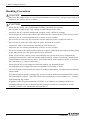
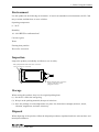
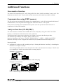
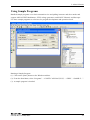
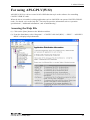
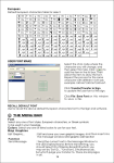
1
PC-HELPER
High Speed & Function IEEE-488.2 I/F Board
for CardBus
GP-IB(CB)F
High Speed IEEE-488.2 I/F Board for CardBus
GP-IB(CB)FL
User’s Manual
CONTEC CO.,LTD.
Check Your Package
Thank you for purchasing the CONTEC product.
The product consists of the items listed below.
Check, with the following list, that your package is complete. If you discover damaged or missing items,
contact your retailer.
Product Configuration List
- PC Card(One of the following)
[GP-IB(CB)F or GP-IB(CB)FL] …1
- First step guide …1
- CD-ROM *1 [API-PAC(W32)] …1
- Connection Cable (CB-GPIB) …1
- PC-Card Attachment(CARD-AT1) …1set
*1 The CD-ROM contains the driver software and User’s Guide (this guide)
PC Card
Connection Cable
CD-ROM
[API-PAC(W32)]
GP-IB(CB)F, GP-IB(CB)FL
First step guide
PC-Card Attachment
i
Copyright
Copyright 2003 CONTEC CO., LTD. ALL RIGHTS RESERVED
No part of this document may be copied or reproduced in any form by any means without prior written
consent of CONTEC CO., LTD.
CONTEC CO., LTD. makes no commitment to update or keep current the information contained in this
document. The information in this document is subject to change without notice.
All relevant issues have been considered in the preparation of this document. Should you notice an
omission or any questionable item in this document, please feel free to notify CONTEC CO., LTD.
Regardless of the foregoing statement, CONTEC assumes no responsibility for any errors that may
appear in this document nor for results obtained by the user as a result of using this product.
Trademarks
MS, Microsoft, Windows and Windows NT are trademarks of Microsoft Corporation. Other brand and
product names are trademarks of their respective holder.
ii
GP-IB(CB)F, GP-IB(CB)FL
Table of Contents
Check Your Package............................................................................................................................ i
Copyright ............................................................................................................................................ ii
Trademarks ......................................................................................................................................... ii
Table of Contents .............................................................................................................................. iii
1.
BEFORE USING THE PRODUCT
1
About the PC Card.............................................................................................................................. 1
Features........................................................................................................................................ 1
Support Software ......................................................................................................................... 2
Cable & Connector (Option) ...................................................................................................... 3
Customer Support ............................................................................................................................... 4
Web Site....................................................................................................................................... 4
Limited Three-Years Warranty .......................................................................................................... 4
How to Obtain Service ....................................................................................................................... 4
Liability .............................................................................................................................................. 4
Safety Precautions .............................................................................................................................. 5
Safety Information....................................................................................................................... 5
Handling Precautions................................................................................................................... 6
Environment ................................................................................................................................ 7
Inspection..................................................................................................................................... 7
Storage ......................................................................................................................................... 7
Disposal ....................................................................................................................................... 7
2.
SETUP
9
What is Setup? .................................................................................................................................... 9
Using the PC Card under Windows Using the Driver Library API-PAC(W32) ........................ 9
Using the PC Card under Windows Using Software Other than the Driver Library
API-PAC(W32)............................................................................................................................ 9
Using the PC Card under an OS Other than Windows ............................................................. 10
Step 1 Installing the Software .......................................................................................................... 11
About the driver to be used ....................................................................................................... 11
Starting the Install Program....................................................................................................... 12
For using API-GPIB(98/PC)xx ................................................................................................. 13
For using API-GPLV(W32) ...................................................................................................... 15
Step 2 Setting the Hardware............................................................................................................. 16
Connecting the PC Card to the Connecter Cable ...................................................................... 16
Fitting the PC Card Attachment ................................................................................................ 17
Insert the PC Card ..................................................................................................................... 18
GP-IB(CB)F, GP-IB(CB)FL
iii
Step 3 Installing the Hardware ......................................................................................................... 19
Turning on the PC...................................................................................................................... 19
Setting with the Found New Hardware Wizard ........................................................................ 19
Step 4 Initializing the Software ........................................................................................................ 21
For using API-GPIB(98/PC)xx ................................................................................................. 23
For using API-GPLV(W32) ...................................................................................................... 24
Step 5 Checking Operations with the Diagnosis Program ............................................................... 25
What is the Diagnosis Program? ............................................................................................... 25
Check Method............................................................................................................................ 25
Setup Troubleshooting...................................................................................................................... 28
Symptoms and Actions .............................................................................................................. 28
If your problem cannot be resolved........................................................................................... 28
3.
EXTERNAL CONNECTION
29
How to connect the connectors......................................................................................................... 29
Connector shape......................................................................................................................... 29
Notes on cable connection ......................................................................................................... 30
4.
FUNCTIONS
33
Bus Master Function......................................................................................................................... 33
Bus Master Transfer .................................................................................................................. 33
Basic GPIB Functions ...................................................................................................................... 34
Master/slave function ................................................................................................................ 34
Communication function ........................................................................................................... 34
Serial poll/parallel poll/SRQ send functions............................................................................. 34
My address setting ..................................................................................................................... 34
Additional Functions ........................................................................................................................ 35
Line monitor function ................................................................................................................ 35
Communication using FIFO memory........................................................................................ 35
Analyzer function (GP-IB(CB)F).............................................................................................. 35
5.
ABOUT SOFTWARE
39
CD-ROM Directory Structure .......................................................................................................... 39
About Software for Windows........................................................................................................... 40
For using API-GPIB(98/PC)xx ........................................................................................................ 40
Accessing the Help File ............................................................................................................. 40
Using Sample Programs ............................................................................................................ 41
For using API-GPLV(W32) ............................................................................................................. 43
Accessing the Help File ............................................................................................................. 43
Function List .............................................................................................................................. 44
Using Sample Programs ............................................................................................................ 47
Uninstalling the API Function Libraries ................................................................................... 48
iv
GP-IB(CB)F, GP-IB(CB)FL
About Software for Linux ................................................................................................................ 49
Driver Software Install Procedure............................................................................................. 49
Accessing the Help File............................................................................................................. 50
Using Sample Programs ............................................................................................................ 50
Uninstalling the driver............................................................................................................... 50
6.
ABOUT HARDWARE
51
For detailed technical information ................................................................................................... 51
Hardware specification ..................................................................................................................... 51
GP-IB(CB)F, GP-IB(CB)FL
v
vi
GP-IB(CB)F, GP-IB(CB)FL
1. Before Using the Product
1. Before Using the Product
About the PC Card
This PC card is a multi-function, high-speed GPIB communication card that complies with IEEE-488.1
and IEEE-488.2. The card is a PC Card Standard compliant CardBus card with support for bus master
operation. The card can be used to control communications with devices that support the GPIB interface
and perform GPIB bus line data analysis on any PC that has a PC Card Standard compliant CardBus
Type II PC card slot.
You can use the supplied driver library to develop application software using any programming
language that supports the Win32 API routines (such as Visual Basic or Visual C++), or using LabVIEW.
Features
Complies with the IEEE-488.2 standard
- As the card complies with the IEEE-488.2 standard, you can control any external device that supports this
standard.
Data transfer speed 1.5Mbyte/sec max.
- The maximum data transfer speed for communications is 1.5Mbyte/sec.
Supports bus master operation
- The bus master data transfer function enables large quantities of data to be transferred between the
PC Card and PC without loading the CPU.
Internal 2Kbyte FIFO buffers for send and receive
- The PC Card has separate 2Kbyte FIFO buffers for sending and receiving data, allowing both small
and large volumes of data to be transferred at high speed.
-
Interface messages also use a FIFO to enable high-speed transmission.
Built-in GPIB bus analyzer function [GP-IB(CB)F]
- The PC Card features a bus analyzer function.
This not only allows the signals on the GPIB bus to analyzed, but also permits signal analysis to be
performed while the PC card is performing GPIB communications
Built-in SPAS event function
- In addition to the functions of the earlier GPIB controller (μPD7210), the PC Card also supports the
SPAS event generated when a serial poll occurs. This gives you a high level of flexibility in
constructing your system.
Internal high-precision timer
- The PC Card includes a high-precision application timer to allow accurate time monitoring to be
performed from Windows.
Long term availability
- As the PC Card uses a high-speed GPIB controller developed by CONTEC (upwardly compatible
with the μPD7210), reliable long term availability is ensured.
Diagnostic program
- A diagnostic program is supplied to support system development. The diagnostic program can be used to
check hardware operation (interrupts and I/O addresses) and to perform simple communication tests with
connected devices.
GP-IB(CB)F, GP-IB(CB)FL
1
1. Before Using the Product
Other
- A function is provided to read all control lines and data lines. This enables various operations to be
performed from the application. [Includes control line latch function.]
Support Software
You should use CONTEC support software according to your purpose and development environment.
NOTE:
This hardware does not support Windows 95 and Windows NT4.0/3.51.
Driver Software Package API-PAC(W32) (Bundled)
API-PAC(W32) is the library software that provides the commands for CONTEC hardware products in the form of
Windows standard Win32 API functions (DLL). It makes it easy to create high-speed application software taking
advantage of the CONTEC hardware using various programming languages that support Win32 API functions, such as
Visual Basic and Visual C++.
It can also be used by the installed diagnosis program to check hardware operations.
CONTEC provides download services (at http://www.contec.com/apipac/) to supply the updated drivers and
differential files.
For details, read Help on the bundled CD-ROM or visit the CONTEC’s Web site.
< Operating environment >
OS
Windows XP, Server 2003, 2000, Me, 98, etc..
Adaptation language
Visual C++ .NET, Visual C# .NET, Visual Basic .NET, Visual C++, Visual Basic,
Delphi, C++Builder, etc..
API-GPLV(W32) library supporting LabVIEW (Bundled)
API-GPLV(W32) is a driver created according to the National Instruments Corporation’s GPIB function style. The
driver is software to control the CONTEC GPIB board (PC Cards) using a LabVIEW-based GPIB system or existing
application program.
It can also be used by the installed diagnosis program to check hardware operations.
CONTEC provides download services (at http://www.contec.com/gplv/) to supply the updated drivers and differential
files.
For details, read Help on the bundled CD-ROM or visit the CONTEC’s Web site.
< Operating environment >
OS
Windows XP, Server 2003, 2000, Me, 98, etc..
Adaptation language
LabVIEW, Visual C++ .NET, Visual C# .NET, Visual Basic .NET, Visual C++,
Visual Basic, Delphi, C++Builder, etc..
2
GP-IB(CB)F, GP-IB(CB)FL
1. Before Using the Product
Linux version of general-purpose count driver: API-GPIB(LNX)
(Supplied: Stored on the API-PAC(W32) CD-ROM)
This driver is used to control CONTEC GPIB boards (PC Cards) from within Linux.
You can control CONTEC GPIB boards easily using the shared library called from the user application,
the device driver (module) for each kernel version, and the board (PC Cards) configuration program
(config).
CONTEC provides download services (at http://www.contec.com/apipac/) to supply the updated drivers
and differential files.
For details, read Help on the bundled CD-ROM or visit the CONTEC’s Web site.
< Operating environment >
OS
RedHatLinux, TurboLinux, etc..
(For details on supported distributions, refer to Help available after installation.)
Adaptation language
gcc, etc..
Cable & Connector (Option)
GPIB cable (2m)
GPIB cable (4m)
GPIB Connector
*
: PCN-T02
: PCN-T04
: CN-GP/C
This is useful if the cable used to connect to the instrument or other
device is obstructed by the device's case. See the troubleshooting
section at the end of Chapter 2.
Check the CONTEC’s Web site for more information on these options.
GP-IB(CB)F, GP-IB(CB)FL
3
1. Before Using the Product
Customer Support
CONTEC provides the following support services for you to use CONTEC products more efficiently and
comfortably.
Web Site
Japanese
English
Chinese
http://www.contec.co.jp/
http://www.contec.com/
http://www.contec.com.cn/
Latest product information
CONTEC provides up-to-date information on products.
CONTEC also provides product manuals and various technical documents in the PDF.
Free download
You can download updated driver software and differential files as well as sample programs available in
several languages.
Note! For product information
Contact your retailer if you have any technical question about a CONTEC product or need its price,
delivery time, or estimate information.
Limited Three-Years Warranty
CONTEC products are warranted by CONTEC CO., LTD. to be free from defects in material and
workmanship for up to three years from the date of purchase by the original purchaser.
Repair will be free of charge only when this device is returned freight prepaid with a copy of the original
invoice and a Return Merchandise Authorization to the distributor or the CONTEC group office, from
which it was purchased.
This warranty is not applicable for scratches or normal wear, but only for the electronic circuitry and
original PC Card s. The warranty is not applicable if the device has been tampered with or damaged
through abuse, mistreatment, neglect, or unreasonable use, or if the original invoice is not included, in
which case repairs will be considered beyond the warranty policy.
How to Obtain Service
For replacement or repair, return the device freight prepaid, with a copy of the original invoice. Please
obtain a Return Merchandise Authorization Number (RMA) from the CONTEC group office where you
purchased before returning any product.
*
No product will be accepted by CONTEC group without the RMA number.
Liability
The obligation of the warrantor is solely to repair or replace the product. In no event will the warrantor
be liable for any incidental or consequential damages due to such defect or consequences that arise from
inexperienced usage, misuse, or malfunction of this device.
4
GP-IB(CB)F, GP-IB(CB)FL
1. Before Using the Product
Safety Precautions
Understand the following definitions and precautions to use the product safely.
Safety Information
This document provides safety information using the following symbols to prevent accidents resulting in
injury or death and the destruction of equipment and resources. Understand the meanings of these labels
to operate the equipment safely.
DANGER
DANGER indicates an imminently hazardous situation which, if not avoided, will
result in death or serious injury.
WARNING
WARNING indicates a potentially hazardous situation which, if not avoided, could
result in death or serious injury.
CAUTION
CAUTION indicates a potentially hazardous situation which, if not avoided, may
result in minor or moderate injury or in property damage.
GP-IB(CB)F, GP-IB(CB)FL
5
1. Before Using the Product
Handling Precautions
DANGER
Do not use the product where it is exposed to flammable or corrosive gas. Doing so may result in an
explosion, fire, electric shock, or failure.
CAUTION
-
Mount the PC card in a PC Card Standard CardBus compatible PC card slot.
-
Do not strike or bend the PC Card. Doing so could damage the PC Card.
Otherwise, the PC Card may malfunction, overheat, cause a failure or breakage.
-
Do not subject the socket used to connect the cable to the PC card to knocks or other excessive force.
Otherwise, the PC card may malfunction, overheat, or cause a failure.
-
Do not insert or remove the PC card in the card slot when the power is turned on to the PC.
-
Do not insert or remove the cable while the power is turned on to the PC.
-
Connect the cable to the card before inserting the card into the PC.
Otherwise, the PC card may malfunction, overheat, or cause a failure.
-
Do not try to remove the cable from the connecter on the PC card without pressing the locking spring
as this may prevent the cable from being securely connected.
-
When you use the PC Card in a noisy environment or are nervous about noise, strengthen the
earthing between the PC Card frame and the frame ground of your PC. Specifically, install the PC
Card attachment, and then connect the PC Card frame and the frame ground of the PC to earth the
PC Card frame (e.g. using an earth cable).
-
Ensure that the PC power supply has sufficient capacity for all mounted cards.
An inadequate power supply may cause misoperation, overheating, or faults.
-
The specifications of this product are subject to change without notice for enhancement and quality
improvement.
Even when using the product continuously, be sure to read the manual and understand the contents.
-
Do not modify the product. CONTEC will bear no responsibility for any problems, etc., resulting
from modifying this product.
-
Regardless of the foregoing statements, CONTEC is not liable for any damages whatsoever
(including damages for loss of business profits) arising out of the use or inability to use this
CONTEC product or the information contained herein.
6
GP-IB(CB)F, GP-IB(CB)FL
1. Before Using the Product
Environment
Use this product in the following environment. If used in an unauthorized environment, the PC Card
may overheat, malfunction, or cause a failure.
Operating temperature
0 - 50°C
Humidity
10 - 90%RH (No condensation)
Corrosive gases
None
Floating dust particles
Not to be excessive
Inspection
Inspect the product periodically as follows to use it safely.
- The gold-plated leads of the bus connector
have no stain or corrosion.
- Check that the bus connector
and its cable have been
plugged correctly.
Storage
When storing this product, keep it in its original packing form.
(1) Put the PC card in the storage bag.
(2) Wrap it in the packing material, then put it in the box.
(3) Store the package at room temperature at a place free from direct sunlight, moisture, shock,
vibration, magnetism, and static electricity.
Disposal
When disposing of the product, follow the disposal procedures stipulated under the relevant laws and
municipal ordinances.
GP-IB(CB)F, GP-IB(CB)FL
7
1. Before Using the Product
8
GP-IB(CB)F, GP-IB(CB)FL
2. Setup
2. Setup
This chapter explains how to set up the PC Card .
What is Setup?
Setup means a series of steps to take before the product can be used.
Different steps are required for software and hardware
The setup procedure varies with the OS and applications used.
Using the PC Card under Windows
Using the Driver Library API-PAC(W32)
This section describes the setup procedure to be performed before you can start developing application
programs for the PC Card using the bundled CD-ROM “Driver Package API-PAC(W32)”.
Taking the following steps sets up the software and hardware. You can use the diagnosis program later
to check whether the software and hardware function normally.
Step 1 Installing the Software
Step 2 Setting the Hardware
Step 3 Installing the Hardware
Step 4 Initializing the Software
Step 5 Checking Operations with the Diagnosis Program
If Setup fails to be performed normally, see the “Setup Troubleshooting” section at the end of this
chapter.
Using the PC Card under Windows
Using Software Other than the Driver Library
API-PAC(W32)
For setting up software other than API-PAC(W32), refer to the manual for that software. See also the
following parts of this manual as required.
This chapter Step 2 Setting the Hardware
This chapter Step 3 Installing the Hardware
Chapter 3 External Connection
Chapter 6 About Hardware
GP-IB(CB)F, GP-IB(CB)FL
9
2. Setup
Using the PC Card under an OS Other than Windows
For using the PC Card under an OS other than Windows, see the following parts of this manual.
This chapter Step 2 Setting the Hardware
Chapter 3 External Connection
Chapter 6 About Hardware
10
GP-IB(CB)F, GP-IB(CB)FL
2. Setup
Step 1 Installing the Software
This explains how to install the driver library.
Before installing the hardware on the PC, install the driver library from the API-PAC(W32)
CD-ROM provided with the PC Card.
The following description assumes the operating system as Windows XP. Although some user
interfaces are different depending on the OS used, the basic procedure is the same.
About the driver to be used
Two GPIB communication drivers come with your PC Card: API-GPIB(98/PC) and
API-GPLV(W32).
API-GPIB(98/PC) provides a CONTEC proprietary function interface.
API-GPLV(W32) provides a function interface equivalent to that from National Instruments
Corporation (hereafter NI), allowing the GPIB488, GPIB488.2, and VISA functions of LabVIEW to be
used directly and application programs created for NI PC cards to run without modification.
Selection guide
Given below is a guideline for easily selecting the appropriate driver for the PC Card.
driver to be used
Purpose
API-GPIB(98/PC)
- Used to use CONTEC functions
- To make the PC Card operate as fast as possible
- To convert (digitize) binary and string data easily
API-GPLV(W32)
- To use existing applications for NI PC Cards
- To use LabVIEW
- Familiar with NI functions but not with CONTEC functions
GP-IB(CB)F, GP-IB(CB)FL
11
2. Setup
Starting the Install Program
(1) Load the CD-ROM [API-PAC(W32)] on your PC.
(2) The API-PAC(W32) Installer window appears automatically.
If the panel does not appear, run (CD-ROM drive letter):\AUTORUN.exe.
(3) Click on the [Install Development or Execution Environment] button.
CAUTION
Before installing the software in Windows XP, Server 2003, 2000, or NT, log in as a user with
administrator privileges.
12
GP-IB(CB)F, GP-IB(CB)FL
2. Setup
For using API-GPIB(98/PC)xx
Select API-GPIB(98/PC)
(1) The following dialog box appears to select “Driver Type” and “Install Type”.
(2) Select “GPIB Communication”.
(3) Select “Driver, Help, etc..(Full Install)”.
(4) Click on the [Install] button.
GP-IB(CB)F, GP-IB(CB)FL
13
2. Setup
Executing the Installation
(1) Follow the on-screen instructions to proceed to install.
(2) When the required files have been copied, the “Perform a hardware setup now” and “Show readme
file” check boxes are displayed.
When you are installing the software or hardware for the first time:
1) Uncheck “Perform a hardware setup now”.
2) Click on the [Finish] button. Go to Step 2 to set and plug the hardware.
* When the hardware has already been installed:
Check “Perform a hardware setup now”, then go to Step 4 “Initializing the Software”.
You have now finished installing the software.
14
GP-IB(CB)F, GP-IB(CB)FL
2. Setup
For using API-GPLV(W32)
Select API-GPLV(W32)
(1) The following dialog box appears to select “Driver Type” and “Install Type”.
(2) Select “GPIB for LabVIEW API-GPLV(W32)”.
(3) Select “Driver, Help, etc..(Full Install)”.
(4) Click on the [Install] button.
Executing the Installation
(1) Follow the on-screen instructions to proceed to install.
(2) The driver installation is completed when the GPIB setup utility is started.
If you are installing the software and hardware for the first time, click on the [Cancel] button in this
step to terminate the installation procedure.
*
When the hardware has already been installed:
Go to “For Using API-GPLV(W32)” in Step 4 "Initializing the Software".
GP-IB(CB)F, GP-IB(CB)FL
15
2. Setup
Step 2 Setting the Hardware
This section explains how to setup the PC card and mount the card in the PC.
Ensure that the PC you are using has a PC Card Standard compliant CardBus Type II PC card slot.
Connecting the PC Card to the Connecter Cable
Plug the PC card connector end of the supplied cable [CB-GPIB] into the PC card.
CAUTION
-
When plugging in the cable, align the cable connector with the PC card socket and push firmly into
place. Do not apply any excessive force to the socket on the PC card as this may damage the socket
or result in a bad connection.
-
Do not insert or remove the cable or PC card while the power is turned on to the PC.
Connection Cable
Locking Spring
Locking Metal Fitting
PC Card
PC Card Socket Side
Figure 2.1. Connecting the PC Card to the Connecter Cable
16
GP-IB(CB)F, GP-IB(CB)FL
2. Setup
Fitting the PC Card Attachment
Fitting the PC card attachment helps prevent the cable from being disconnected if force is accidentally
applied to the top of the connector.
Refer to the instructions supplied with the PC card attachment for details on how to fit it.
CAUTION
When using other PC cards in the same PC, the PC card attachment may obstruct the other cards and
make them difficult to insert. In this case, please remove the PC card attachment.
PC Card Attachment
PC Card
PC Card Socket Side
Figure 2.2. Fitting the PC Card Attachment
GP-IB(CB)F, GP-IB(CB)FL
17
2. Setup
Insert the PC Card
Check that the power to the PC is turned off and insert the card into the PC card slot on the PC.
Firmly insert the card into the slot with the orientation indicated by the arrow symbol on the card, as
shown in Figure 2.3.
The PC card has a key to prevent it from being inserted incorrectly. Do not try to force the card into the
slot the wrong way around as this may damage the card or the slot on the PC. Also, check the card slot
on your PC as the slots on some PCs are oriented so that cards is inserted with the top side facing down.
Refer to the manual for your PC for instructions on how to remove the card.
Figure 2.3. Insert the PC Card
CAUTION
Take note of the following points as inappropriate handling of the PC card may damage the card or
connector socket and may result in a bad connection.
-
18
Always insert the PC card with the correct orientation and in accordance with the instructions.
-
Do not hold the card by the cable or connector when inserting the card into the slot.
-
Do not move the PC with the cable still plugged in.
-
Do not apply any excessive force to the cable socket on the PC card such as by pulling on the
cable connector.
-
Do not place any objects on top of the cable connector.
GP-IB(CB)F, GP-IB(CB)FL
2. Setup
Step 3 Installing the Hardware
For using an expansion PC card under Windows, you have to let the OS detect the I/O addresses and IRQ
to be used by the PC card. The process is referred to as installing the hardware.
In the case of using two or more PC cards, make sure you install one by one with the Found New
Hardware Wizard.
Turning on the PC
Turn on the power to your PC.
CAUTION
-
The PC card cannot be properly installed unless the resources (I/O addresses and interrupt level) for
the PC card can be allocated. Before attempting to install the PC card, first determine what PC
resources are free to use.
-
The resources used by each PC card do not depend on the location of the PC card slot or the PC Card
itself. If you remove two or more PC cards that have already been installed and then remount one of
them on the computer, it is unknown that which one of the sets of resources previously assigned to
the two PC cards is assigned to the remounted PC card. In this case, you must check the resource
settings.
Setting with the Found New Hardware Wizard
(1) The “Found New Hardware Wizard” will be started.
Select “Install from a list or specific location[Advanced]”, then click on the [Next] button.
If you are using Windows NT 4.0, the “Found New Hardware Wizard” is not started.
Go to Step 4 “Initializing the Software”.
GP-IB(CB)F, GP-IB(CB)FL
19
2. Setup
(2) Specify that folder on the CD-ROM which contains the setup information (INF) file to register the
PC Card.
* The name of the PC card
you have just added is
displayed.
- GP-IB(CB)F
- GP-IB(CB)FL
Source folder
The setup information (INF) file is contained in the following folder on the bundled CD-ROM.
\INF\WDM\Gpib
\INF\WDM\Gpib
You have now finished installing the hardware
20
GP-IB(CB)F, GP-IB(CB)FL
2. Setup
Step 4 Initializing the Software
The driver library requires the initial setting to recognize the execution environment. It is called the
initialization of the driver library.
Setting the device name
(1) Start Device Manager. Select [My Computer] - [Control Panel] - [System], then select the [Device
Manager] tab.
(Alternatively, right click on My Computer and select Properties.)
* The name of the PC card
you have just added is
displayed.
- GP-IB(CB)F
- GP-IB(CB)FL
(2) The installed hardware appears under the "CONTEC Devices" node in the tree.
Open the device tree and select the device (the selected device appears highlighted).
Click [Properties].
GP-IB(CB)F, GP-IB(CB)FL
21
2. Setup
(3) The device property page appears.
Enter the device name in the common settings tab page.
*
The device name displayed initially is a default value. You can leave this default name if you wish.
*
Ensure that the same device name is not used for more than one device.
22
GP-IB(CB)F, GP-IB(CB)FL
2. Setup
For using API-GPIB(98/PC)xx
Advanced settings (for the API-GPIB(98/PC)xx)
(1) Open the advanced settings tab page and specify the settings.
Specify a "Driver No." that is not used by any other CONTEC GPIB PC card. The "Driver No."
determines the API routine names to use.
(2) When you have finished, click [OK].
You have now finished installing the initial setting of Software.
GP-IB(CB)F, GP-IB(CB)FL
23
2. Setup
For using API-GPLV(W32)
Advanced settings (for the API-GPLV(W32))
(1) Open the advanced settings tab page and specify the settings.
The following window opens if "Use API-GPLV(W32)" is selected.
- Interface Name :
From the list, select the PC
Card to be set up.
- GPIB Address :
Set the device address of the
PC Card .
The primary address can be set
to 0 - 30.
- Termination Methods :
Set the termination format.
- I/O Timeout :
Set the transmit/receive
time-out period.
- System Controller :
Select whether to use the PC
Card as a system controller.
(2) When you have finished, click [OK].
You have now finished installing the initial setting of Software.
24
GP-IB(CB)F, GP-IB(CB)FL
2. Setup
Step 5 Checking Operations with the Diagnosis
Program
Use the diagnosis program to check that the PC card and driver software work normally, thereby you can
confirm that they have been set up correctly.
What is the Diagnosis Program?
The diagnosis program diagnoses the states of the PC card and driver software.
It can also be used as a simple checker when an external device is actually connected.
Using the “Diagnosis Report” feature reports the driver settings, the presence or absence of the PC card,
I/O status, and interrupt status.
Check Method
Perform the transmit/receive test and check the execution environment with the PC Card connected to
the remote device.
Before diagnosis, check the address of the remote device. Prepare the user’s guide and command
reference for the remote device as required (to perform testing smoothly).
Starting the Diagnosis Program
Click the [Diagnosis] button on the device property page to start the diagnosis program.
GP-IB(CB)F, GP-IB(CB)FL
25
2. Setup
Check of GPIB communication
The remote device address setting, communication data format setting, and main dialog boxes are
displayed.
(1) Specify the remote device address and
click on the [OK] button.
(2) Specify the communication format and click on
the [OK] button.
(3) The main dialog box appears.
* The name of the PC card
you have just added is
displayed.
- GP-IB(CB)F
- GP-IB(CB)FL
The following commands can be used to check GPIB operations.
”Send”:
Sends the typed character string with a delimiter to the remote device.
”Receive”:
Receives data from the remote device and displays it along with the number of data
items.
”Trigger”:
Sends a trigger command to the remote device.
”Polling”:
Polls the remote device and displays the obtained status byte.
Note
When communication has been completed successfully, “xxxxx completed normally” is displayed
as the “return value”.
26
GP-IB(CB)F, GP-IB(CB)FL
2. Setup
Diagnosis Report
(1) Clicking on [Diagnosis] displays detailed data including PC card settings and the diagnosis results
while saving them in text format.
The results are saved and displayed as a text file (GpibRep.txt) in the install folder (Program
Files\CONTEC\API-PAC(W32)).
The diagnosis program performs "PC card presence/absence check", "driver file test", "PC card
setting test", and so on.
* The name of the PC card
you have just added is
displayed.
- GP-IB(CB)F
- GP-IB(CB)FL
Click on [Diagnosis].
(2) A diagnosis report is displayed as shown below.
* The name of the PC card
you have just added is
displayed.
- GP-IB(CB)F
- GP-IB(CB)FL
GP-IB(CB)F, GP-IB(CB)FL
27
2. Setup
Setup Troubleshooting
Symptoms and Actions
A GPIB error occurs.
The remote device address may be incorrect or the GPIB cable may not yet be connected.
The OS won't normally get started or detect the PC card.
Turn off the power to the PC and remove the PC card. Reboot the OS and use [Control Panel] [Add/Remove Applications] to uninstall the "CONTEC API-GPIB(WDM) driver".
Turn off the PC again, plug the PC card, and restart the OS. Let the OS detect the PC card and use
API-TOOL Configuration to make PC card settings over again.
If your problem cannot be resolved
Refer to the troubleshooting section of GPIB HELP and API-GPLV HELP.
28
GP-IB(CB)F, GP-IB(CB)FL
3. External Connection
3. External Connection
This chapter describes the interface connectors on the PC card.
Check the information available here when connecting an external device.
How to connect the connectors
Connector shape
Use the interface connectors on the CB-GPIB cable to connect to external devices.
Interface Connector(CN1)
NX30TA-32PAA (HIROSE)
2.0m
1
13
12
24
RC40-24RR (HIROSE)
SHIELD
(Attention)
ATN
(Service Request)
SRQ
(Interface Clear)
IFC
(Not Data Accepted) NDAC
Handshake
bus (Not Ready for Data) NRFD
(Data Valid)
DAV
Management bus(End or Identify)
EOI
Data bus DIO4
Data bus DIO3
Data bus DIO2
Data bus DIO1
Management bus
12
11
10
9
8
7
6
5
4
3
2
1
24
23
22
21
20
19
18
17
16
15
14
13
GND (Ground)
GND (Ground)
GND (Ground)
GND (Ground)
GND (Ground)
GND (Ground)
GND (Ground)
REN(Remote Enable)Management bus
DIO8 Data bus
DIO7 Data bus
DIO6 Data bus
DIO5 Data bus
Applicable connector(cable) :
GPIB cable(IEEE-488 rated)
* Please refer to chapter 1 for more information on the supported cable and accessories.
Figure 3.1. Cable(CB-GPIB) Shape and Interface Connector Pin Layout
GP-IB(CB)F, GP-IB(CB)FL
29
3. External Connection
Notes on cable connection
The GPIB has restrictions on the number of devices connected and the cable length according to the
standard.
(1) The maximum number of interfaces (external devices) is 15, which can be connected to one system.
(2) The maximum total length of cables that can be used to interconnect a group of devices in one bus
system is “2 m x (the number of devices)” or 20 m, whichever is shorter. (JIS C1901-1987).
Note, however, the individual cables between devices must be within 4 m long. Some examples are
given below.
-
System with a total of two devices
2 m x (Number of devices = 2) < 20 m
The maximum total length of cables for this system is therefore 4 m.
3765
-
System with a total of three devices
2 m x (Number of devices = 3) < 20 m
The maximum total length of cables for this system is therefore 6 m. The two cables used in the
system must be [2 m + 4 m] or [2 m + 2 m] in length so that neither is longer than 4 m.
-
System with a total of fifteen devices
2 m x (Number of devices = 15) > 20 m
The maximum total length of cables for this system is therefore 20 m.
3765
30
GP-IB(CB)F, GP-IB(CB)FL
3. External Connection
(3) The cables in the system must not form a loop.
3765
(4) Unplug the cable from any device which is left off for some reason such as a fault.
(5) When powering the measurement system, turn on the measuring instrument first and then on the PC.
(6) Neither unplug/plug the cable nor turn on/off the device during communication. Doing so stops the
operation or causes an error, resulting in trouble.
(7) The talker and listener must be addressed to talk and to listen, respectively, by the controller before
the talker can send messages to the listener.
(8) At least two thirds of all the devices connected must be turned on.
GP-IB(CB)F, GP-IB(CB)FL
31
3. External Connection
32
GP-IB(CB)F, GP-IB(CB)FL
4. Functions
4. Functions
This section describes the functions of the PC card.
Bus Master Function
Bus Master Transfer
The bus master data transfer function uses time when the PCI bus is idle to perform direct DMA transfer
of data between the PC card and the application memory space. The application memory space means a
static area defined using a normal variable declaration. Under Windows, the application memory space
is represented using logical addresses and does not necessarily map on to a continuous physical address
space. However, the PC card is able to transfer data consecutively to the discontinuous physical address
space. Bus master data transfer can be performed for a maximum 64MBytes physical memory area. The
actual memory size able to be used when setting up a data transfer in an application depends on the OS
type and the size of memory in the PC.
GP-IB(CB)F, GP-IB(CB)FL
33
4. Functions
Basic GPIB Functions
Master/slave function
The PC card can be used as either the master (controller) or slave, depending on a setting in the property
page. When used as the master, the PC card can send IFC (InterFace Clear) at any timing and control the
REN (Remote ENable) line.
Communication function
The PC card can send and receive data in accordance with the IEEE 488 Standard. You can add
delimiters and EOI (End of Identify) to outgoing data depending on the software settings.
Serial poll/parallel poll/SRQ send functions
The following functions can be used depending on the master/slave configuration.
Master
Serial poll
Parallel poll
Slave
Status byte setting
SRQ (Service ReQuest) transmission
Response to parallel polling
My address setting
The GPIB address (my address) of the PC card can be set by API-TOOL Configuration
(API-GPIB(98/PC)xx) or Configuration Utility (API-GPLV(W32)). No setting is required on the PC
card.
34
GP-IB(CB)F, GP-IB(CB)FL
4. Functions
Additional Functions
Line monitor function
The states of all control lines (IFC, ATN, SRQ, REN, EOI, DAV, NRFD, and NDAC) can be read. The
latch data can also be read. You can also read the current state of the data lines (DIO1 to DIO8).
Communication using FIFO memory
The PC card can use on-board FIFO memory for communication. As the PC card controls this form of
communication, it can be performed at high speed irrelevant to the PC’s CPU speed.
Note, however, that the actual communication speed is set to the speed of the slowest device in
compliance with the GPIB standard.
Analyzer function (GP-IB(CB)F)
The state transition of all lines in the GPIB cable can be analyzed by using the on-PC Card FIFO
memory. (A maximum of 64K data items can be collected.)
This function can be used to locate the cause of a failure or to check data flowing on lines.
The function is provided by the analyzer utility (Analyzer.exe).
Open the Start Menu, then select “CONTEC API-PAC(W32)” – “GPIB” – “GPIB ANALYZER”.
Otherwise, directly execute “Program Files\API-PAC(W32)\GPIB\ANALYZER\Analyzer.exe”.
Running Method
(1) Install the PC card on your PC according to Step 2 “Setting the Hardware” and Step 3 “Installing the
Hardware” in Chapter 2 “Setup”.
After having installed the PC card, connect the PC Card to an instrument for analysis. The PC card
can communicate with the instrument while executing analysis.
Example 1 of Connection:
3765
One PC Card communicating the instrument while analyzing
Example 2 of Connection:
3765
PC1: Only the analyzer is executed.
PC2: Communicating with the measuring instrument
GP-IB(CB)F, GP-IB(CB)FL
35
4. Functions
(2) If more than one PC Card (device) that supports the analyzer function is installed in the PC, the
following window appears when you start the analyzer utility. Select the device name set for the
hardware in the property page, then click [Select Board]. (This window does not appear if only one
PC Card is present that supports the analyzer function.)
(3) Click on the [Start Analyze] button. The analyzer utility analyzes the subsequent changes to lines.
When the communication you want to analyze has been completed, click on the [Stop Analyze]
button. The analysis results will be displayed on the screen.
36
GP-IB(CB)F, GP-IB(CB)FL
4. Functions
Convenient usage
(1) Using the start and end triggers
During analysis, the analyzer utility can obtain data only when a specific condition is satisfied in the
entire session of communication. The condition that can be specified is a communication status
(polling, transmit/receive, etc.), a change to the control line (EOL, SRQ, ATN, etc.), a data line
match (specified ASCII code), or a delimiter match.
Select “Set Trigger Condition” from the “Set” menu.
The analyzer utility works as follows with the settings made on the Trigger Set Dialog below.
-
The analyzer utility starts analysis the moment IFC changes.
-
The analyzer utility ends analysis upon transmit/receive of data “CR” (0DH).
(2) Saving analysis data
Once saved, obtained analysis data can be opened again with the analyzer utility. Since analysis
data is saved in CSV format as well, you can reference and edit the data using a proper program such
as Excel.
GP-IB(CB)F, GP-IB(CB)FL
37
4. Functions
(3) Viewing analysis data in a chart
The analysis utility can display analysis data in a chart.
38
GP-IB(CB)F, GP-IB(CB)FL
5. About Software
5. About Software
CD-ROM Directory Structure
\
|– Autorun.exe
| Readmej.html
| Readmeu.html
.
.
|–––APIPAC
| |––AIO
| | |––DISK1
| | |––DISK2
| | |––……
| | |––DISKN
| |––AioWdm
| |––CNT
| |––DIO
| |––……
.
.
| ––HELP
| |––Aio
| |––Cnt
| |––……
.
.
| ––INF
| |––WDM
| |––Win2000
| |––Win95
.
.
|––linux
| |––cnt
| |––dio
| |––……
.
.
| ––Readme
.
.
| ––Release
| |––API_NT
| |––API_W95
.
.
| ––UsersGuide
Installer Main Window
Version information on each API-TOOL (Japanese)
Version information on each API-TOOL (English)
Windows driver file
HELP file
Each INF file for OS
Linux driver file
Readme file for each driver
Driver file on each API-TOOL
(For creation of a user-specific install program)
Hardware User's Guide(PDF files)
GP-IB(CB)F, GP-IB(CB)FL
39
5. About Software
About Software for Windows
The bundled CD-ROM “Driver library API-PAC(W32)” contains the functions that provide the
following features:
-
All of the master mode, slave mode, and interrupt level can be set by software.
-
Three-wire handshaking is employed to assure transfer even between the sending and receiving
devices different in speed.
For details, refer to the help file. The help file provides various items of information such as “Function
Reference”, “Sample Programs”, and “FAQs”. Use them for program development and troubleshooting.
For using API-GPIB(98/PC)xx
Accessing the Help File
(1) Click on the [Start] button on the Windows taskbar.
(2) From the Start Menu, select “Programs” – “CONTEC API-PAC(W32)” – “GPIB” – “API-GPIB
HELP” to display help information.
40
GP-IB(CB)F, GP-IB(CB)FL
5. About Software
Using Sample Programs
Bundled sample programs cover basic transmit/receive and polling in master and slave modes and
support ADVANTEST Multimeters, YEW voltage generators, and SONY Tektronix oscilloscopes.
Use these sample programs as references for program development and operation check.
Running a Sample Program
(1) Click on the [Start] button on the Windows taskbar.
(2) From the Start Menu, select “Programs” – “CONTEC API-PAC(W32)” – “GPIB” – “SAMPLE…”.
(3) A sample program is invoked.
GP-IB(CB)F, GP-IB(CB)FL
41
5. About Software
Sample Programs - Examples
-Master Mode
:
Executes a series of operations in master mode.
-Slave Mode
:
Executes a series of operations in slave mode.
-Multi-meter
:
Triggers a multimeter periodically (based on the timer and events) to
sample and display data.
-Voltage Source control
:
Allows the master to gain control of a digital voltmeter at fixed
intervals.
-Oscilloscope 1
:
Receives screen data from an oscilloscope and displays it in a graph.
-Oscilloscope 2
:
Receives screen data from an oscilloscope and saves it in CSV format.
-MultiLine Message
:
Creates a multiline message for the remote device.
[Master Mode]
[MultiLine Message]
[Slave Mode]
[Oscilloscope 2]
[Voltage Source control]
42
GP-IB(CB)F, GP-IB(CB)FL
5. About Software
For using API-GPLV(W32)
API-GPLV(W32) is a driver created in NI’s GPIB function style as the software for controlling
CONTEC GPIB PC cards.
When the driver is installed, existing applications such as LabVIEW can operate CONTEC GPIB PC
cards. For details, refer to the help file. The help file provides information such as “operation
specifications”, “additional information”, and “troubleshooting”.
Accessing the Help File
(1) Click on the [Start] button on the Windows taskbar.
(2) From the Start Menu, select “Programs” – “CONTEC API-PAC(W32)” – “GPLV” – “API-GPLV
HELP” to display help information.
GP-IB(CB)F, GP-IB(CB)FL
43
5. About Software
Function List
Up to now the NI-488.2 PC Card -Level Calls
Function Name
Action Outline
ibask
Return information about software configuration parameters.
ibcac
Become Active Controller.
ibcmd
Send GPIB commands.
ibcmda
Send GPIB commands asynchronously.
ibconfig
Change the software configuration parameters.
ibdma
Enable or disable DMA.
ibeos
Configure the end-of-string (EOS) termination mode or character.
ibeot
Enable/disable auto-assertion of GPIB EOI line at the end of write.
ibfind
Open and initialize a GPIB board.
ibgts
Go from Active Controller to Standby.
ibist
Set or clear the board individual status bit for parallel polls.
iblines
Return the status of the eight GPIB control lines.
ibln
Check for the presence of a device on the bus.
ibloc
Go to local.
ibnotify
Asynchronously notify user when one or more GPIB events occur.
ibonl
Place the device online or offline.
ibpad
Change the primary address.
ibppc
Parallel poll configure.
ibrd
Read data from a device into a user buffer.
ibrda
Read data asynchronously from a device into a user buffer.
ibrdf
Read data from a device into a file.
ibrpp
Conduct a parallel poll.
ibrsc
Request or release system control.
ibrsv
Request service and change the serial poll status byte.
ibsad
Change or disable the secondary address.
ibsic
Assert IFC (Interface Clear).
ibsre
Set or clear the Remote Enable (REN) line.
ibstop
Abort asynchronous I/O operation.
ibtmo
Change or disable the I/O timeout period.
ibwait
Wait for GPIB events.
ibwrt
Write data to a device from a user buffer.
ibwrta
Write data asynchronously to a device from a user buffer.
ibwrtf
Write data to a device from a file.
44
GP-IB(CB)F, GP-IB(CB)FL
5. About Software
Up to now the Ni-488.2 Device-Level Calls
Function Name
Action Outline
ibask
Return information about software configuration parameters.
ibbna
Change the access board of a device.
ibclr
Clear a specific device.
ibconfig
Change the software configuration parameters.
ibdev
Open and initialize a device
ibeos
Configure the end-of-string (EOS) termination mode or character.
ibeot
Enable/disable auto-assertion of GPIB EOI line at the end of write.
ibln
Check for the presence of a device on the bus.
ibloc
Go to local.
ibnotify
Asynchronously notify user when one or more GPIB events occur.
ibonl
Place the device online or offline.
ibpad
Change the primary address.
ibpct
Pass control to another GPIB device with Controller capability.
ibppc
Parallel poll configure.
ibrd
Read data from a device into a user buffer.
ibrda
Read data asynchronously from a device into a user buffer.
ibrdf
Read data from a device into a file.
ibrpp
Conduct a parallel poll.
ibrsp
Conduct a serial poll.
ibsad
Change or disable the secondary address.
ibstop
Abort asynchronous I/O operation.
ibtmo
Change or disable the I/O timeout period.
ibtrg
Trigger selected device.
ibwait
Wait for GPIB events.
ibwrt
Write data to a device from a user buffer.
ibwrta
Write data asynchronously to a device from a user buffer.
ibwrtf
Write data to a device from a file.
GP-IB(CB)F, GP-IB(CB)FL
45
5. About Software
NI-488.2 Calls for Multiple Devices
Function Name
Action Outline
AllSpoll
Serial poll all devices.
DevClear
Clear a single device.
DevClearList
Clear multiple devices.
EnableLocal
Enable operations from the front panel of deceives (leave remote programming mode).
EnableRemote
Enable remote GPIB programming for devices.
FindListn
Find listening devices on the GPIB.
FindRQS
Determine which device is requesting service.
PassControl
Pass control to another device with Controller capability.
PPoll
Perform a parallel poll on the GPIB.
PPollConfig
Configure a device to respond to parallel polls.
PPollUnconfig
Unconfigure devices for parallel polls.
RcvRespMsg
Read data bytes from a device that is already addressed to talk.
ReadStatusByte
Serial poll a single device.
Receive
ReceiveSetup
Read data bytes from a device.
Address a device to be a Talker and the interface board to be a Listener in preparation for
RcvRespMsg.
ResetSys
Reset and initialize IEEE 488.2-compliant devices.
Send
Send data bytes to a device.
SendCmds
Send GPIB command bytes.
SendDataBytes
Send data bytes to devices that are already addressed to listen.
SendIFC
Reset the GPIB by sending interface clear.
SendList
Send data bytes to multiple GPIB devices.
SendLLO
Send the Local Lockout (LLO) message to all devices.
SendSetup
Set up devices to receive data in preparation for SendDataBytes.
SetRWLS
Place devices in Remote With Lockout State.
TestSRQ
Determine the current state of the GPIB Service Request (SRQ) line.
TestSys
Cause IEEE 488.2-compliant devices to conduct self-test.
Trigger
Trigger a device.
TriggerList
Trigger multiple devices.
WaitSRQ
Wait until a device asserts the GPIB Service Request (SRQ) line.
46
GP-IB(CB)F, GP-IB(CB)FL
5. About Software
Using Sample Programs
Sample programs can execute basic transmit/receive and polling.
Use these sample programs as references for program development and operation check.
The sample programs are stored in \Program Files\CONTEC\API-PAC(W32)\GPLV\Samples.
Running a Sample Program
(1) Click on the [Start] button on the Windows taskbar.
(2) From the Start Menu, select “Programs” – “CONTEC API-PAC(W32)” – “GPLV” – “SAMPLE
GPLV”.
(3) A sample program is invoked.
Program example
-GpibTest
GP-IB(CB)F, GP-IB(CB)FL
:
Executes initialization, transmission, reception, and polling.
47
5. About Software
Uninstalling the API Function Libraries
To uninstall API-PAC(W32), follow the procedure below.
(1) Click on the [Start] button on the Windows taskbar. From the Start Menu, select “Settings” –
“Control Panel”.
(2) Double-click on “Add/Remove Programs” in the Control Panel.
(3) Select “CONTEC API-GPIB(WDM) driver” , “CONTEC API-GPIB(98/PC)xx” or “CONTEC
API-GPLV(W32) xx”. [Change/Remove] button.
Follow the on-screen instructions to uninstall the function libraries.
48
GP-IB(CB)F, GP-IB(CB)FL
5. About Software
About Software for Linux
The Linux version GPIB communication driver API-GPIB(LNX) contains the functions that provide the
following features:
-
All of the master mode, slave mode, and interrupt level can be set by software.
-
Three-wire handshaking is employed to assure transfer even between the sending and receiving
devices different in speed.
For details, refer to the help file. The help file provides various items of information such as “Function
Reference”, “Sample Programs”, and “FAQs”. Use them for program development and troubleshooting.
Driver Software Install Procedure
The Linux version for GPIB communication driver, API-GPIB(LNX), is supplied as a compressed file
/linux/gpib/cgpibXXX.tgz on the bundled API-PAC(W32)CD-ROM. (Note: XXX represents the driver
version.)
Mount the CD-ROM as shown below, copy the file to an arbitrary directory, and decompress the file to
install the driver.
For details on using the driver, refer to readme.txt and the help file in HTML format extracted by
installation.
To install the driver, log in as a superuser.
Decompression and setup procedure
# cd
# mount /dev/cdrom /mnt/cdrom
Mount the CD-ROM.
# cp /mnt/cdrom/linux/gpib/cgpibXXX.tgz ./ Copy the compressed file.
# tar xvfz cgpibXXX.tgz
Decompress the compressed file.
................
# cd contec/cgpib
# make
Compile the file.
................
# make install
Install.
................
# cd config
# ./config
Set up the board to be used.
..... Set as follows .........
# ./contec_gpib_start.sh
Start the driver.
# cd
GP-IB(CB)F, GP-IB(CB)FL
49
5. About Software
Accessing the Help File
(1) Invoke a web browser in your X-Window environment.
(2) In the browser, open gpibhelp.htm in the contec/cgpib/help directory.
Using Sample Programs
Sample programs have been prepared for specific basic applications.
Sample programs for each language are contained in the contec/cgpib/samples directory. For compiling
them, refer to the manual for the desired language.
Uninstalling the driver
To uninstall the driver, use the uninstall shell script contained in the contec/cgpib directory. For details,
check the contents of the script.
50
GP-IB(CB)F, GP-IB(CB)FL
6. About Hardware
6. About Hardware
This chapter provides hardware specifications and hardware-related supplementary information.
For detailed technical information
For further detailed technical information (“Technical Reference” including the information such as an
I/O map, configuration register, etc.), visit the Contec's web site (http://www.contec.com/support/) to
call for it.
Hardware specification
The following tables list the hardware specifications of the board.
GP-IB(CB)F
Table 6.1. Specification <GP-IB(CB)F> < 1 / 2 >
Item
Specifications
GPIB
Number of channel
1ch
Conforms to IEEE-488.1, 488.2(GPIB)standards
Transfer format
8-bit parallel, 3-wire handshake system
Transfer rate
1.5Mbyte/sec
Data buffer size
2Kbyte send, 2Kbyte receive
Signal logic
Negative logic
L level : 0.8V or less,
H level : 2.0V or more
Cable length between
device
4m or less *1
Total cable length
20m or less
Connectable number of
device
15 devices (Max.)
Analyzer buffer size
64K data points
(1 data point: Control signals + DIO1 to 8)
Bus master section
DMA channels
2ch
Transfer bus width
32-bit
Transfer data length
8 PCI Words length (Max.)
Transfer rate
80Mbyte/sec
Scatter/Gather function
64Mbyte/ch
GP-IB(CB)F, GP-IB(CB)FL
51
6. About Hardware
Table 6.1. Specification <GP-IB(CB)F> < 2 / 2 >
Item
Specifications
Common section
I/O address
Any 128-byte boundary
Interrupt
1 level use
Consumed current
3.3VDC 400mA (Max.)
Operating conditions
0 - 50°C, 10 - 90%RH (No condensation)
Length of supplied cable 2.0m
PC card slot
specifications
PC Card Standard CardBus
Card size
TYPE II
Weight
40g (250g including cable)
*1 For details, see item (2) in Chapter3, "Connecting Cables".
GP-IB(CB)FL
Table 6.2. Specification <GP-IB(CB)FL> < 1 / 2 >
Item
Specifications
GPIB
Number of channel
1ch
Conforms to IEEE-488.1, 488.2(GPIB)standards
Transfer format
8-bit parallel, 3-wire handshake system
Transfer rate
1.5Mbyte/sec
Data buffer size
2Kbyte send, 2Kbyte receive
Signal logic
Negative logic
L level : 0.8V or less,
H level : 2.0V or more
Cable length between
device
4m or less *1
Total cable length
20m or less
Connectable number of
device
15 devices (Max.)
Bus master section
52
DMA channels
2ch
Transfer bus width
32-bit
Transfer data length
8 PCI Words length (Max.)
Transfer rate
80Mbyte/sec
Scatter/Gather function
64Mbyte/ch
GP-IB(CB)F, GP-IB(CB)FL
6. About Hardware
Table 6.2. Specification <GP-IB(CB)FL> < 2 / 2 >
Item
Specifications
Common section
I/O address
Any 128-byte boundary
Interrupt
1 level use
Consumed current
3.3VDC 400mA (Max.)
Operating conditions
0 - 50°C, 10 - 90%RH (No condensation)
Length of supplied cable 2.0m
PC card slot
specifications
PC Card Standard CardBus
Card size
TYPE II
Weight
40g (250g including cable)
*1 For details, see item (2) in Chapter3, "Connecting Cables".
External dimensions
2.0m
17.0mm
58.4mm
54.0mm
17.4mm
85.6mm
Connection Cable
20.0mm
PC Card
5.0mm
9.0mm
Table 6.3. Interface function
Code
Function
SH1
Source handshake functions
AH1
Acceptor handshake functions
T6
Basic talker, serial polling, MLA talker release
L4
Basic listener MTA listener release
TE0
No extended talker functions
LE0
No extended listener functions
SR1
Service request function
RL1
Remote function
DC1
Device clear function
DT1
Device trigger function
PP1
Configuration by remote message
C1
System controller function
C2
IFC send, controller in-charge
C3
REN send
C4
Response to SRQ
C26
Interface message send, parallel polling
GP-IB(CB)F, GP-IB(CB)FL
53
GP-IB(CB)F
GP-IB(CB)FL
User’s Manual
CONTEC CO., LTD.
November 2007 Edition
3-9-31, Himesato, Nishiyodogawa-ku, Osaka 555-0025, Japan
Japanese http://www.contec.co.jp/
English http://www.contec.com/
Chinese http://www.contec.com.cn/
No part of this document may be copied or reproduced in any form by any means without prior written
consent of CONTEC CO., LTD.
[11122007]
[04172003]
[11122007_rev5]
Management No. A-46-744
Parts No.
LYCP262