1
®
5820A
Oscilloscope Calibrator
Operators Manual
PN 802154
April 1999 Rev.3, 11/06
© 1999-2006 Fluke Corporation, All rights reserved. Printed in USA
All product names are trademarks of their respective companies.
LIMITED WARRANTY & LIMITATION OF LIABILITY
Each Fluke product is warranted to be free from defects in material and workmanship under
normal use and service. The warranty period is one year and begins on the date of shipment.
Parts, product repairs and services are warranted for 90 days. This warranty extends only to the
original buyer or end-user customer of a Fluke authorized reseller, and does not apply to fuses,
disposable batteries or to any product which, in Fluke's opinion, has been misused, altered,
neglected or damaged by accident or abnormal conditions of operation or handling.Fluke
warrants that software will operate substantially in accordance with its functional specifications for
90 days and that it has been properly recorded on non-defective media. Fluke does not warrant
that software will be error free or operate without interruption.
Fluke authorized resellers shall extend this warranty on new and unused products to end-user
customers only but have no authority to extend a greater or different warranty on behalf of Fluke.
Warranty support is available if product is purchased through a Fluke authorized sales outlet or
Buyer has paid the applicable international price. Fluke reserves the right to invoice Buyer for
importation costs of repair/replacement parts when product purchased in one country is
submitted for repair in another country.
Fluke's warranty obligation is limited, at Fluke's option, to refund of the purchase price, free of
charge repair, or replacement of a defective product which is returned to a Fluke authorized
service center within the warranty period.
To obtain warranty service, contact your nearest Fluke authorized service center or send the
product, with a description of the difficulty, postage and insurance prepaid (FOB Destination), to
the nearest Fluke authorized service center. Fluke assumes no risk for damage in transit.
Following warranty repair, the product will be returned to Buyer, transportation prepaid (FOB
Destination). If Fluke determines that the failure was caused by misuse, alteration, accident or
abnormal condition of operation or handling, Fluke will provide an estimate of repair costs and
obtain authorization before commencing the work. Following repair, the product will be returned
to the Buyer transportation prepaid and the Buyer will be billed for the repair and return
transportation charges (FOB Shipping Point).
THIS WARRANTY IS BUYER'S SOLE AND EXCLUSIVE REMEDY AND IS IN LIEU OF ALL
OTHER WARRANTIES, EXPRESS OR IMPLIED, INCLUDING BUT NOT LIMITED TO ANY
IMPLIED WARRANTY OF MERCHANTABILITY OR FITNESS FOR A PARTICULAR PURPOSE.
FLUKE SHALL NOT BE LIABLE FOR ANY SPECIAL, INDIRECT, INCIDENTAL OR
CONSEQUENTIAL DAMAGES OR LOSSES, INCLUDING LOSS OF DATA, WHETHER
ARISING FROM BREACH OF WARRANTY OR BASED ON CONTRACT, TORT, RELIANCE OR
ANY OTHER THEORY.
Since some countries or states do not allow limitation of the term of an implied warranty, or
exclusion or limitation of incidental or consequential damages, the limitations and exclusions of
this warranty may not apply to every buyer. If any provision of this Warranty is held invalid or
unenforceable by a court of competent jurisdiction, such holding will not affect the validity or
enforceability of any other provision.
Fluke Corporation
P.O. Box 9090
Everett, WA 98206-9090
U.S.A.
5/94
Fluke Europe B.V.
P.O. Box 1186
5602 BD Eindhoven
The Netherlands
SAFETY TERMS IN THIS MANUAL
This instrument has been designed and tested in accordance with IEC publication
1010-1 (1992-1), Safety Requirements for Electrical Measuring, Control and Laboratory
Equipment, and ANSI/ISA-S82.01-1994, and CAN/CSA-C22.2 No. 1010.1-92. This User
Manual contains information, warning, and cautions that must be followed to ensure safe
operation and to maintain the instrument in a safe condition. Use of this equipment in a
manner not specified herein may impair the protection provided by the equipment.
This instrument is designed for IEC 1010-1 Installation Category II use. It is not designed
for connection to circuits rated over 4800 VA.
WARNING statements identify conditions or practices that could result in personal injury
or loss of life.
CAUTION statements identify conditions or practices that could result in damage to
equipment.
SYMBOLS MARKED ON EQUIPMENT
WARNING Risk of electric shock. Refer to the manual (see the Index for
references).
GROUND Ground terminal to chassis (earth).
Attention Refer to the manual (see the Index for references). This
symbol indicates that information about usage of a feature is contained in
the manual.
AC POWER SOURCE
The instrument is intended to operate from an ac power source that will not apply more
than 264V ac rms between the supply conductors or between either supply conductor
and ground. A protective ground connection by way of the grounding conductor in the
power cord is required for safe operation.
USE THE PROPER FUSE
To avoid fire hazard, for fuse replacement use only the specified unit: 100 or 120 V
operation, 2 ampere/250 volt time delay; 200 or 240 V operation, 1 ampere/250 volt time
delay.
GROUNDING THE INSTRUMENT
The instrument utilizes controlled overvoltage techniques that require the instrument to
be grounded whenever normal mode or common mode ac voltages or transient voltages
may occur. The enclosure must be grounded through the grounding conductor of the
power cord, or through the rear panel ground binding post.
USE THE PROPER POWER CORD
Use only the power cord and connector appropriate for the voltage and plug
configuration in your country.
Use only a power cord that is in good condition.
Refer power cord and connector changes to qualified service personnel.
DO NOT OPERATE IN EXPLOSIVE ATMOSPHERES
To avoid explosion, do not operate the instrument in an atmosphere of explosive gas.
DO NOT REMOVE COVER DURING OPERATION
To avoid personal injury or death, do not remove the instrument cover without first
removing the power source connected to the rear panel. Do not operate the instrument
without the cover properly installed. Normal calibration is accomplished with the cover
closed. Access procedures and the warnings for such procedures are contained both in
this manual and in the Service Manual. Service procedures are for qualified service
personnel only.
DO NOT ATTEMPT TO OPERATE IF PROTECTION MAY BE IMPAIRED
If the instrument appears damaged or operates abnormally, protection may be impaired.
Do not attempt to operate the instrument under these conditions. Refer all questions of
proper instrument operation to qualified service personnel.
Table of Contents
Chapter
1
Title
Introduction and Specifications......................................................... 1-1
1-1.
1-2.
1-3.
1-4.
1-5.
1-6.
1-7.
1-8.
1-9.
1-10.
1-11.
1-12.
1-13.
1-14.
1-15.
1-16.
1-17.
1-18.
1-19.
1-20.
1-21.
1-22.
1-23.
1-24.
1-25.
1-26.
1-27.
1-28.
1-29.
1-30.
2
Page
Introduction...........................................................................................
Operation Overview..............................................................................
Local Operation ................................................................................
Remote Operation (RS-232).............................................................
Remote Operation (IEEE-488) .........................................................
Where to Go from Here ........................................................................
Instruction Manuals ..............................................................................
5820A Operators Manual .................................................................
5820A Service Manual .....................................................................
Specifications........................................................................................
General Specifications......................................................................
Voltage Output Specifications..........................................................
DC Volt Measure Specifications ......................................................
Edge Specifications ..........................................................................
Leveled Sine Wave Specifications (≤ 600 MHz) .............................
Time Marker Specifications .............................................................
Wave Generator Specifications ........................................................
1 ns Pulse Generator Specifications .................................................
Trigger Signal Specifications (Pulse Function)................................
Trigger Signal Specifications (Time Marker Function) ...................
Trigger Signal Specifications (Edge Function) ................................
Trigger Signal Specifications (Square Wave Voltage Function) .....
Trigger Signal Specifications (TV) ..................................................
Tunnel Diode Drive Capability ........................................................
Oscilloscope Input Resistance Measurement Specifications............
Oscilloscope Input Capacitance Measurement Specifications .........
Overload Measurement Specifications .............................................
External Reference Input Specifications ..........................................
Auxiliary Input/Output Specifications .............................................
Current Output Specifications ..........................................................
1-3
1-4
1-5
1-5
1-6
1-7
1-7
1-7
1-8
1-8
1-10
1-11
1-11
1-12
1-13
1-13
1-14
1-14
1-14
1-15
1-15
1-15
1-15
1-15
1-15
1-15
1-15
1-16
1-16
1-16
Preparing for Operation ...................................................................... 2-1
2-1.
Introduction........................................................................................... 2-3
i
5820A
Operators Manual
2-2.
2-3.
2-4.
2-5.
2-6.
2-7.
2-8.
3
2-3
2-4
2-4
2-5
2-7
2-7
2-8
Feature ................................................................................................. 3-1
3-1.
3-2.
3-3.
3-4.
4
Unpacking and Inspection ....................................................................
Replacing The Fuse ..............................................................................
Selecting Line Voltage..........................................................................
Connecting To Line Power ...................................................................
How to Contact Fluke ...........................................................................
Placement and Rack Mounting .............................................................
Cooling Considerations.........................................................................
Introduction...........................................................................................
Front Panel Features .............................................................................
Rear Panel Features ..............................................................................
Setup Softkey Menu Trees....................................................................
3-3
3-3
3-3
3-10
Front Panel Operation......................................................................... 4-1
4-1.
4-2.
4-3.
4-4.
4-5.
4-6.
4-7.
4-8.
4-9.
4-10.
4-11.
4-12.
4-13.
4-14.
4-15.
4-16.
4-17.
4-18.
4-19.
4-20.
4-21.
4-22.
4-23.
4-24.
4-25.
4-26.
4-27.
4-28.
4-29.
4-30.
4-31.
4-32.
4-33.
4-34.
4-35.
4-36.
4-37.
4-38.
4-39.
Introduction...........................................................................................
Turning on the Calibrator .....................................................................
Warming up the Calibrator ...................................................................
Using the Softkeys ................................................................................
Using the Setup Menu...........................................................................
Using the Instrument Setup Menu ....................................................
Utility Functions Menu ....................................................................
Using the Format EEPROM Menu ..............................................
Resetting the Calibrator ........................................................................
Using the Operate and Standby Modes.................................................
Connecting the Calibrator to the UUT..................................................
Starting the Calibrator...........................................................................
The Output Signal ............................................................................
Editing and Error Output Settings ........................................................
Adjusting the Output Signal .............................................................
Keying in a Value ........................................................................
Adjusting Values with the Rotary Knob ......................................
Using u and a ..................................................................
Displaying the Output Error .............................................................
Resetting the Calibrator....................................................................
Calibrating the Voltage Amplitude on an Oscilloscope........................
The VOLTAGE Function.................................................................
The V/DIV Menu .............................................................................
Shortcuts for Setting the Voltage Amplitude ...................................
The TRIG (Trigger) Menu................................................................
Oscilloscope Amplitude Calibration Procedure ...............................
Calibrating the Pulse and Frequency Response on an Oscilloscope.....
The Edge Function ...........................................................................
The TRIG (Trigger) Menu................................................................
Oscilloscope Pulse Response Calibration Procedure .......................
Pulse Response Calibration Using a Tunnel Diode Pulser...............
The Leveled Sine Wave Function ....................................................
Shortcuts for Setting the Frequency and Voltage.............................
The MORE OPTIONS Menu ...........................................................
Sweeping Through a Frequency Range............................................
Oscilloscope Frequency Response Calibration Procedure ...............
Calibrating the Time Base of an Oscilloscope......................................
The Time Marker..............................................................................
The TRIG (Trigger) Menu................................................................
ii
4-3
4-3
4-4
4-4
4-4
4-5
4-5
4-6
4-7
4-7
4-7
4-8
4-8
4-8
4-9
4-9
4-10
4-11
4-11
4-11
4-11
4-12
4-13
4-13
4-14
4-14
4-15
4-15
4-16
4-17
4-18
4-19
4-21
4-21
4-22
4-23
4-24
4-25
4-26
Contents (continued)
4-40.
4-41.
4-42.
4-43.
4-44.
4-45.
4-46.
4-47.
4-48.
4-49.
4-50.
4-51.
4-52.
4-53.
5
Time Base Marker Calibration Procedure for an Oscilloscope ........
Testing the Trigger................................................................................
Testing Video Triggers .........................................................................
Verifying Pulse Capture........................................................................
The TRIG (Trigger) Menu................................................................
Measuring the DC Calibration Output of an Oscilloscope ...................
Measuring Input Impedance and Capacitance ......................................
Input Impedance Measurement ........................................................
Input Capacitance Measurement ......................................................
Testing Overload Protection .................................................................
Using Auxiliary Input (AUXIN)...........................................................
Setting the Output Channel...................................................................
Using an External Reference ................................................................
Using the Current Output Function ......................................................
4-26
4-27
4-29
4-30
4-31
4-32
4-32
4-33
4-33
4-34
4-35
4-36
4-36
4-36
Remote Operation ............................................................................... 5-1
5-1.
5-2.
5-3.
5-4.
5-5.
5-6.
5-7.
5-8.
5-9.
5-10.
5-11.
5-12.
5-13.
5-14.
5-15.
5-16.
5-17.
5-18.
5-19.
5-20.
5-21.
5-22.
5-23.
5-24.
5-25.
5-26.
5-27.
5-28.
5-29.
5-30.
5-31.
5-32.
5-33.
5-34.
5-35.
5-36.
5-37.
5-38.
Introduction...........................................................................................
Setting up the IEEE-488 Port for Remote Control ...............................
IEEE-488 Port Setup Procedure .......................................................
Testing the IEEE-488 Port................................................................
Setting up the RS-232 Host Port for Remote Control...........................
RS-232 Host Port Setup Procedure ..................................................
Testing the RS-232 Host Port...........................................................
Testing RS-232 Host Port Operation using a Terminal ...............
Testing RS-232 Host Port Operation using Visual Basic ............
Setting up the RS-232 UUT Port for Remote Control..........................
RS-232 UUT Port Setup Procedure..................................................
Testing the RS-232 UUT Port via RS-232 Host Port.......................
Testing RS−232 UUT Port Operation via a Terminal..................
Testing RS-232 UUT Port Operation using Visual Basic............
Testing the RS-232 UUT Port via IEEE-488 Port............................
Changing between Remote and Local Operation .................................
Local State ........................................................................................
Local with Lockout State..................................................................
Remote State.....................................................................................
Remote with Lockout State ..............................................................
RS-232 Interface Overview ..................................................................
IEEE-488 Interface Overview...............................................................
Using Commands..................................................................................
Types of Commands.........................................................................
Device−Dependent Commands....................................................
Common Commands....................................................................
Query Commands.........................................................................
Interface Messages (IEEE-488) ...................................................
Compound Commands.................................................................
Coupled Commands .....................................................................
Overlapped Commands ................................................................
Sequential Commands..................................................................
Commands that Require the Calibration Switch to be Enabled ...
Commands for RS-232 Only........................................................
Commands for IEEE-488 Only ....................................................
Command Syntax .............................................................................
Parameter Syntax Rules ...............................................................
Extra Space or Tab Characters .....................................................
iii
5-4
5-4
5-7
5-8
5-11
5-11
5-13
5-13
5-15
5-16
5-16
5-17
5-19
5-20
5-21
5-23
5-23
5-23
5-23
5-23
5-24
5-25
5-26
5-28
5-28
5-28
5-28
5-28
5-30
5-30
5-31
5-31
5-31
5-31
5-32
5-33
5-33
5-34
5820A
Operators Manual
5-39.
5-40.
5-41.
5-42.
5-43.
5-44.
5-45.
5-46.
5-47.
5-48.
5-49.
5-50.
5-51.
5-52.
5-53.
5-54.
5-55.
5-56.
5-57.
5-58.
5-59.
5-60.
5-61.
5-62.
5-63.
5-64.
6
5-35
5-35
5-36
5-37
5-37
5-39
5-39
5-40
5-40
5-40
5-40
5-41
5-42
5-42
5-42
5-42
5-44
5-44
5-45
5-45
5-45
5-46
5-47
5-47
5-48
5-48
Remote Codes ..................................................................................... 6-1
6-1.
6-2.
6-3.
7
Terminators ..................................................................................
Incoming Character Processing....................................................
Response Message Syntax ...........................................................
Checking 5820A Status ........................................................................
Serial Poll Status Byte (STB) ...........................................................
Service Request (SRQ) Line ........................................................
Service Request Enable Register (SRE).......................................
Programming the STB and SRE ..................................................
Event Status Register (ESR).............................................................
Event Status Enable (ESE) Register ............................................
Bit Assignments for the ESR and ESE.........................................
Programming the ESR and ESE...................................................
Instrument Status Register (ISR)......................................................
Instrument Status Change Registers.............................................
Instrument Status Change Enable Registers.................................
Bit Assignments for the ISR, ISCR, and ISCE ............................
Programming the ISR, ISCR, and ISCE ......................................
Output Queue ...................................................................................
Error Queue ......................................................................................
Remote Program Examples...................................................................
Guidelines for Programming the Calibrator .....................................
Writing an SRQ and Error Handler ..................................................
Using *OPC?, *OPC, and *WAI .....................................................
Taking an Impedance Measurement.................................................
Using the RS-232 UUT Port to Control an instrument ....................
Input Buffer Operation .....................................................................
Introduction........................................................................................... 6-3
Command Summary by Function ......................................................... 6-3
Summary of Commands and Queries ................................................... 6-8
Maintenance......................................................................................... 7-1
7-1.
7-2.
7-3.
7-4.
7-5.
7-6.
7-7.
7-8.
7-9.
7-10.
7-11.
7-12.
7-13.
7-14.
7-15.
7-16.
7-17.
7-18.
7-19.
7-20.
7-21.
Introduction...........................................................................................
Replacing the Line Fuse .......................................................................
Cleaning the Air Filter ..........................................................................
General Cleaning ..................................................................................
Verification Tables ...............................................................................
DC Voltage Output Verification ......................................................
AC Voltage Amplitude Verification.................................................
AC Voltage Frequency Verification.................................................
DC Voltage Measurement Verification ............................................
Wave Generator Amplitude Verification: 1 MΩ Output Impedance
Wave Generator Amplitude Verification: 50 Ω Output Impedance.
Wave Generator Frequency Verification: 1 MΩ Output Impedance
Leveled Sinewave Verification: Amplitude .....................................
Leveled Sinewave Verification: Frequency .....................................
Leveled Sinewave Verification: Harmonics.....................................
Leveled Sinewave Verification: Flatness .........................................
Edge Verification: Amplitude ..........................................................
Edge Verification: Frequency...........................................................
Edge Verification: Duty Cycle .........................................................
Edge Verification: Rise Time ...........................................................
Tunnel Diode Pulser Verification.....................................................
iv
7-3
7-3
7-4
7-6
7-6
7-6
7-7
7-8
7-8
7-9
7-10
7-11
7-11
7-11
7-12
7-13
7-19
7-19
7-19
7-20
7-20
Contents (continued)
7-22.
7-23.
7-24.
7-25.
7-26.
7-27.
8
7-20
7-21
7-21
7-21
7-21
7-22
Options ................................................................................................. 8-1
8-1.
8-2.
8-3.
8-4.
8-5.
8-6.
8-7.
8-8.
8-9.
8-10.
9
Marker Generator Verification .........................................................
Pulse Generator Verification: Period................................................
Pulse Generator Verification: Pulse Width ......................................
Input Impedance Verification: Resistance........................................
Input Impedance Verification: Capacitance .....................................
Current Verification..........................................................................
Introduction...........................................................................................
5820A-5 Option ....................................................................................
GHz Option...........................................................................................
Using the GHz Option Functions .....................................................
Fast Edge Specifications...................................................................
Leveled Sine Wave (> 600 MHz) Specifications .............................
Time Marker Specifications .............................................................
GHz Option Verification Tables...........................................................
Extended Leveled Sinewave Verification: Flatness .........................
Leveled Sinewave Verification: Harmonics.....................................
8-3
8-3
8-3
8-3
8-4
8-5
8-6
8-7
8-7
8-15
Accessories ......................................................................................... 9-1
9-1.
9-2.
9-3.
9-4.
9-5.
Introduction...........................................................................................
Rack Mount Kit ....................................................................................
IEEE-488 Interface Cables ...................................................................
RS-232 Null-Modem Cables ................................................................
RS-232 Modem Cables.........................................................................
9-3
9-3
9-4
9-4
9-4
Glossary.......................................................................................................
ASCII and IEEE-488 Bus Codes.................................................................
IEEE-488 Interface Card .............................................................................
RS-232/IEEE-488 Cables and Connectors..................................................
Creating a Visual Basic Test Program.........................................................
Error Message .............................................................................................
A-1
B-1
C-1
D-1
E-1
F-1
Appendices
A
B
C
D
E
F
Index
v
5820A
Operators Manual
vi
List of Tables
Table
2-1.
2-2.
3-1.
3-2.
3-3.
4-1.
4-2.
5-1.
5-2.
5-3.
5-4.
5-5.
5-6.
5-7.
5-8.
5-9.
5-10.
5-11.
5-12.
6-1.
6-2.
7-1.
7-2.
7-3.
7-4.
7-5.
7-6.
7-7.
7-8.
7-9.
7-10.
7-11.
7-12.
7-13.
7-14.
Title
Standard Equipment ...............................................................................................
Line Power Cord Types Available from Fluke ......................................................
Front Panel Features...............................................................................................
Rear Panel Features................................................................................................
Factory Default Settings for the SETUP Menus ....................................................
Factory Defaults for SETUP ..................................................................................
Keys That Exit Error Mode....................................................................................
Operating State Transitions....................................................................................
RS-232 Interface Wiring ........................................................................................
RS-232 Emulation of IEEE-488 Messages ............................................................
IEEE-488 Remote Message Coding.......................................................................
IEEE-488 Interface Messages (Receive)................................................................
Interface Messages (Send) .....................................................................................
Commands for RS-232 Only..................................................................................
Commands for IEEE-488 Only ..............................................................................
Units Accepted in Parameters and Used in Responses ..........................................
Terminator Characters............................................................................................
Response Data Types .............................................................................................
Status Register Summary .......................................................................................
Command Summary by Function ..........................................................................
SCOPE Command Parameters ...............................................................................
Replacement Fuses.................................................................................................
DC Voltage Output Verification ............................................................................
AC Voltage Amplitude Verification ......................................................................
AC Voltage Frequency Verification ......................................................................
DC Voltage Measurement Verification..................................................................
Wave Generator Amplitude Verification (into 1 MΩ output impedance) .............
Wave Generator Amplitude Verification (into 50 Ω impedance) ..........................
Wave Generator Frequency Verification (into 1 MΩ Impedance) ........................
Leveled Sinewave Verification: Amplitude ...........................................................
Leveled Sinewave Verification: Frequency ...........................................................
Leveled Sinewave Verification: Harmonics...........................................................
Leveled Sinewave Verification: Flatness ...............................................................
Edge Verification: Amplitude ................................................................................
Edge Verification: Frequency ................................................................................
vii
Page
2-3
2-7
3-4
3-9
3-19
4-6
4-9
5-24
5-24
5-25
5-27
5-29
5-30
5-32
5-32
5-33
5-35
5-36
5-37
6-3
6-32
7-3
7-6
7-7
7-8
7-8
7-9
7-10
7-11
7-11
7-11
7-12
7-13
7-19
7-19
5820A
Operators Manual
7-15.
7-16.
7-17.
7-18.
7-19.
7-20.
7-21.
7-22.
7-23.
7-24.
8-1.
8-2.
8-3.
8-4.
8-5.
9-1.
D-1.
D-2.
F-1.
Edge Verification: Duty Cycle...............................................................................
Edge Verification: Rise Time.................................................................................
Tunnel Diode Pulser Verification ..........................................................................
Marker Generator Verification...............................................................................
Pulse Generator Verification: Period .....................................................................
Pulse Generator Verification: Pulse Width ............................................................
Input Impedance Verification: Resistance .............................................................
Input Impedance Verification: Capacitance ...........................................................
DC Current Verification.........................................................................................
AC Current Verification.........................................................................................
Fast Edge Specifications ........................................................................................
Leveled Sine Wave Specifications (> 600 MHz)...................................................
Time Marker Specifications ...................................................................................
Leveled Sinewave Verification: Flatness ...............................................................
Leveled Sinewave Verification: Harmonics...........................................................
Options and Accessories ........................................................................................
IEEE-488 Connection Cables.................................................................................
Serial Port Connection Cables................................................................................
Error Message Format............................................................................................
viii
7-19
7-20
7-20
7-20
7-21
7-21
7-21
7-21
7-22
7-22
8-4
8-5
8-6
8-7
8-15
9-3
D-1
D-2
F-1
List of Figures
Figure
1-1.
1-2.
1-3.
2-1.
2-2.
3-1.
3-2.
3-3.
3-4.
3-4.
4-1.
4-2.
5-1.
5-2.
5-3.
5-4.
5-5.
5-6.
5-7.
5-8.
5-9.
5-10.
7-1.
7-2.
D-1.
D-2.
D-3.
D-4.
D-5.
Title
5820A Multi-Product Calibrator ............................................................................
RS-232 Remote Connections .................................................................................
5820A Calibrator Dimensional Outline .................................................................
Accessing the Fuse and Selecting Line Voltage ....................................................
Line Power Cord Types Available from Fluke ......................................................
Front Panel View....................................................................................................
Rear Panel View.....................................................................................................
SETUP Softkey Menu Tree ...................................................................................
SETUP Softkey Menu Displays.............................................................................
SETUP Softkey Menu Displays.............................................................................
Oscilloscope connection: channel and External Trigger........................................
Tunnel Diode Pulser Connections..........................................................................
Typical IEEE-488 Remote Control Connections ...................................................
Typical RS-232 Remote Control Connections.......................................................
Testing the IEEE-488 Port .....................................................................................
Testing the RS-232 Host Port ................................................................................
Testing the RS-232 UUT Port via the RS-232 Host Port.......................................
Testing the RS-232 UUT Port via IEEE-488 Port .................................................
Status Register Overview .......................................................................................
Serial Poll Status Byte (STB) and Service Request Enable (SRE) ........................
Event Status Register (ESR) and Event Status Enable (ESE)................................
Bit Assignments for the ISR, ISCEs and ISCRs ....................................................
Accessing the Fuse .................................................................................................
Accessing the Air Filter..........................................................................................
IEEE-488 Connector Pinout (connection side) ......................................................
SERIAL 1 FROM HOST Port Connector Pinout ..................................................
SERIAL 2 TO UUT Port Connector Pinout (connection side) ..............................
Serial Port Connections (DB-9/DB-9) ...................................................................
Serial Port Connections (DB-9/DB-25) .................................................................
ix
Page
1-4
1-6
1-9
2-6
2-7
3-4
3-9
3-10
3-11
3-12
4-7
4-19
5-5
5-6
5-8
5-13
5-18
5-21
5-38
5-39
5-41
5-43
7-4
7-5
D-1
D-2
D-2
D-3
D-4
5820A
Operators Manual
x
Chapter 1
Introduction and Specifications
Title
1-1.
1-2.
1-3.
1-4.
1-5.
1-6.
1-7.
1-8.
1-9.
1-10.
1-11.
1-12.
1-13.
1-14.
1-15.
1-16.
1-17.
1-18.
1-19.
1-20.
1-21.
1-22.
1-23.
1-24.
1-25.
1-26.
1-27.
1-28.
1-29.
1-30.
Introduction...........................................................................................
Operation Overview..............................................................................
Local Operation ................................................................................
Remote Operation (RS-232).............................................................
Remote Operation (IEEE-488) .........................................................
Where to Go from Here ........................................................................
Instruction Manuals ..............................................................................
5820A Operators Manual .................................................................
5820A Service Manual .....................................................................
Specifications........................................................................................
General Specifications......................................................................
Voltage Output Specifications..........................................................
DC Volt Measure Specifications ......................................................
Edge Specifications ..........................................................................
Leveled Sine Wave Specifications (≤ 600 MHz) .............................
Time Marker Specifications .............................................................
Wave Generator Specifications ........................................................
1 ns Pulse Generator Specifications .................................................
Trigger Signal Specifications (Pulse Function)................................
Trigger Signal Specifications (Time Marker Function) ...................
Trigger Signal Specifications (Edge Function) ................................
Trigger Signal Specifications (Square Wave Voltage Function) .....
Trigger Signal Specifications (TV) ..................................................
Tunnel Diode Drive Capability ........................................................
Oscilloscope Input Resistance Measurement Specifications............
Oscilloscope Input Capacitance Measurement Specifications .........
Overload Measurement Specifications.............................................
External Reference Input Specifications ..........................................
Auxiliary Input/Output Specifications..............................................
Current Output Specifications ..........................................................
Page
1-3
1-4
1-5
1-5
1-6
1-7
1-7
1-7
1-8
1-8
1-10
1-11
1-11
1-12
1-13
1-13
1-14
1-14
1-14
1-15
1-15
1-15
1-15
1-15
1-15
1-15
1-15
1-16
1-16
1-16
1-1
5820A
Operators Manual
1-2
Introduction and Specifications
Introduction
1
1-1. Introduction
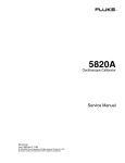
The Fluke Model 5820A Oscilloscope Calibrator (Figure 1-1) is a precise instrument that
calibrates analog and digital oscilloscopes. Specifications are provided in this chapter.
XW Warning
To prevent electric shock or other possible injuries, the 5820A
Calibrator must be operated in the way specified by this manual
or other documentation provided by Fluke.
WCaution
Input voltages exceeding 30 VDC may cause damage to the
instrument. Do not apply voltages except in voltage
measurement mode.
Features of the 5820A Calibrator include the following:
•
Automatic meter error calculation.
•
u and a keys that change the output value to pre-determined cardinal values
for various functions.
•
Programmable entry limits that prevent invalid amounts from being entered.
•
Edge, Leveled Sine, Pulse, Marker, and Wave Generation modes.
•
Accurate oscilloscopic input impedance measurement.
•
Tunnel Diode Pulse compatibility.
•
DC Volt Measure Mode.
•
Current Mode generates both DC and low frequency AC current.
•
1 ns to 500 ns pulse width capability with skew controlled trigger.
1-3
5820A
Operators Manual
OSCILLOSCOPE
5820A CALIBRATOR
• 2GHz
CAT
SOURCE/MEASURE
EXT TRIG CHAN 1
130V
PK
MAX
SOURCE
30V DC
MAX
CHAN 3
CHAN 2
20V PK
MAX
OPR
STBY
VOLT
EDGE
LEVSINE
PREV
MENU
MARKER
7
8
9
μ
V
NEW
REF
CE
RESET
4
5
6
m
n
dBm
MORE
MODES
SETUP
sec
Hz
CHAN
CHAN 4
MEASURE
CHAN 1-5
AUX
INPUT
20V PK
MAX
EDIT
FIELD
100 mA MAX
20V PK MAX
EXT TRIG CHAN 5
20V PK
MAX
1
+/
2
0
3
•
k
M
ENTER
MULT
x
AUX
INPUT
DIV
÷
POWER
I
O
yh001f.eps
Figure 1-1. 5820A Oscilloscope Calibrator
•
External reference.
•
Auxiliary input.
•
5-channel output (5-channel option). The 5-channel option allows you to calibrate up
to five oscilloscope channels simultaneously without changing cables.
•
Simultaneous output of a signal and a trigger signal.
•
600 MHz, Leveled Sine wave output.
•
Optional 600 MHz - 2.1 GHz, Leveled Sine wave output with 150 ps fast edge.
•
Standard IEEE-488 (GPIB) interface, complying with ANSI/IEEE Standards
488.1-1987 and 488.2-1987.
•
EIA Standard RS-232-C serial data interface for printing, displaying, or transferring
internally stored calibration constants, and for remote control of the 5820A.
•
Pass-through RS-232-C serial data interface for communicating with the Unit Under
Test (UUT).
•
Extensive automatic internal self testing and diagnostics of analog and digital
functions.
1-2. Operation Overview
The 5820A Calibrator may be operated at the front panel in the local mode, or remotely
using RS-232 or IEEE-488 ports. For remote operations, several software options are
available to integrate 5820A operation into a wide variety of calibration requirements.
1-4
Introduction and Specifications
Operation Overview
1-3.
Local Operation
Typical local operations include front panel connections to the Unit Under Test (UUT),
and then manual keystroke entries at the front panel to place the calibrator in the desired
output mode. The front panel layout facilitates hand movements from left to right, and
multiply and divide keys make it easy to step up or down at the press of a single key. The
backlit liquid crystal display is easy to read from many different viewing angles and
lighting conditions, and the large, easy-to-read keys are color-coded and provide tactile
feedback when they are pressed.
1-4.
Remote Operation (RS-232)
The Calibrator has two rear-panel serial data RS-232 ports: SERIAL 1 FROM HOST,
and SERIAL 2 TO UUT (Figure 1-2). Each port is dedicated to serial data
communications for operating and controlling the 5820A during calibration procedures.
For complete information on remote operations, see Chapter 5 of the 5820A Operators
Manual.
1
The SERIAL 1 FROM HOST serial data port connects a host terminal or personal
computer to the 5820A. You have several choices for sending commands to the 5820A:
you can enter commands from a terminal (for example, using the Terminal accessory
from Windows using a PC), you can write your own programs using BASIC, or you can
run optional Windows-based software such as 5500/CAL or MET/CAL. The 5500/CAL
software includes more than 200 example procedures covering a wide range of test tools
the 5820A can calibrate. (See Chapter 6 for a discussion of the RS-232 commands.)
The SERIAL 2 TO UUT serial data port connects a UUT to a PC or terminal via the
5820A (see Figure 1-2). This “pass-through” configuration eliminates the requirement for
two COM ports at the PC or Terminal. A set of four commands control the operation of
the SERIAL 2 TO UUT serial port. See Chapter 6 for a discussion of the UUT
commands.
1-5
5820A
Operators Manual
SERIAL 1 FROM HOST port
COM port
PC or Terminal
5820A
RS-232 Remote Operation using the
SERIAL 1 FROM HOST port
SERIAL 1 FROM HOST port
SERIAL 2
TO UUT port
COM port
PC or Terminal
5820A
RS-232 Remote Operation using the
SERIAL 1 FROM HOST and
SERIAL 2 TO UUT ports
Unit Under Test
yh002f.eps
Figure 1-2. RS-232 Remote Connections
1-5.
1-6
Remote Operation (IEEE-488)
The 5820A rear panel IEEE-488 port is a fully programmable parallel interface bus
meeting standard IEEE-488.1 and supplemental standard IEEE-488.2. Under the remote
control of an instrument controller, the 5820A Calibrator operates exclusively as a
“talker/listener.” You can write your own programs using the IEEE-488 command set or
run the optional Windows-based MET/CAL software. (See Chapter 6 for a discussion of
the commands available for IEEE-488 operation.)
Introduction and Specifications
Where to Go from Here
1
1-6. Where to Go from Here
To locate specific information concerning the installation and operation of the 5820A
calibrator, refer to the following list.
•
Unpacking and setup: see Chapter 2
•
Installation and rack mounting: see Chapter 2 and the rack mount kit instruction sheet
•
AC line power and interface cabling: see Chapter 2
•
Controls, indicators, and displays: see Chapter 3
•
Front panel operation: see Chapter 4
•
Cabling to a UUT (Unit Under Test): see Chapter 4
•
Using the auxiliary amplifier: see Chapter 4
•
Remote operation (IEEE-488 or serial): see Chapter 5
•
Accessories to the 5820A Calibrator: see Chapter 9
•
Instrument specifications: see Chapter 1
1-7. Instruction Manuals
The 5820A Manual Set provides complete information for operators and service or
maintenance technicians. The set includes:
•
5820A Operators Manual (PN 802154)
•
5820A Service Manual (PN 673142)
The 5820A Operators Manual ships with the instrument. The 5820A Service Manual is
optional. Order additional copies of the manuals separately using the part number
provided. For ordering instructions, refer to the Fluke Catalog, or ask a Fluke sales
representative (see Chapter 2 for more information).
1-8.
5820A Operators Manual
The 5820A Operators Manual provides complete information for installing the 5820A
Oscilloscope Calibrator and operating it from the front panel keys and in remote
configurations. This manual also provides a glossary of calibration, specifications, and
error code information. The 5820A Operators Manual includes the following topics:
•
Installation
•
Operating controls and features, including front panel operation
•
Remote operation (IEEE-488 bus or serial port remote control)
1-7
5820A
Operators Manual
1-9.
•
Serial port operation (printing, displaying, or transferring data, and setting up for
serial port remote control)
•
Operator maintenance, including verification procedures and calibration approach for
the 5820A
•
Accessories
•
Error Messages
5820A Service Manual
The 5820A Service Manual can be ordered through your local Fluke Sales or Service
representative (see Chapter 2 for more information). The 5820A Service Manual includes:
appropriate theory of operation, performance testing, maintenance, calibration and
verification procedures, and specifications.
1-10. Specifications
The following paragraphs describe the details for the 5820A specifications. All
specifications are valid after allowing a warm-up period of 30 minutes, or twice the time
the 5820A has been turned off. (For example, if the 5820A has been turned off for 5
minutes, the warm-up period is 10 minutes.)
All specifications apply for the temperature and time period indicated. For temperatures
outside of tcal + 5 °C (tcal is the ambient temperature when the 5820A was calibrated),
the temperature coefficient is less than 0.1 times the 1-year specification per °C (limited
to 0 °C - 50 °C).
If you ordered the GHz Option, the following specification tables are supplemented by
the tables with similar headings in Chapter 8.
•
Edge Specifications
•
Leveled Sine Wave Specifications
Refer to Figure 1-3 for the dimensional outline of the 5820A Calibrator.
1-8
Introduction and Specifications
Specifications
1
43.2 cm (17 in)
5820A OSCILLOSCOPE
CALIBRATOR • 2GHz
CAT
SOURCE/MEASURE
EXT TRIG CHAN 1
CHAN 2
VOLT
EDGE
7
8
9
μ
V
NEW
REF
CE
RESET
4
5
6
m
n
dBm
MORE
MODES
SETUP
1
2
3
k
sec
Hz
CHAN
INPUT
+/
0
•
M
MULT
DIV
LEVSINE
17.8 cm
(7 in)
PREV
MENU
OPR
STBY
MARKER
CHAN 2
130V
PK
MAX
SOURCE
30V DC
MAX
CHAN 3
20V PK
MAX
CHAN 4
MEASURE
CHAN 1-5
AUX
INPUT
20V PK
MAX
EDIT
FIELD
CHAN 4
EXT TRIG CHAN 5
20V PK
MAX
ENTER
x
AUX
÷
I
O
47.0 cm (18.5 in)
6.4 cm
(2.5 in)
For Cable
Access
yh003f.eps
Figure 1-3. 5820A Calibrator Dimensional Outline
1-9
5820A
Operators Manual
1-11. General Specifications
Warmup Time
Twice the time since last warmed up, to a maximum of 30 minutes
Settling Time
5 seconds or faster for all functions and ranges
Standard Interfaces
IEEE-488 (GPIB), RS-232
Temperature
Performance
Operating: 0 °C to 50 °C
Calibration (tcal): 15 °C to 35 °C
Storage: -20 °C to 70 °C
Electromagnetic
Compatibility
Designed to operate in Standard Laboratory environments where the Electromagnetic
environment is highly controlled. If used in areas with Electromagnetic fields >1 V/m,
there could be errors in output values. From 80 – 252 MHz, the current output is
susceptible to a field strength of > 0.165 V/M.
Temperature Coefficient
Temperature Coefficient for temperatures outside tcal ±5 °C is 0.1X/°C of 1-year
specification.
[1]
Relative Humidity
Altitude
Operating: < 80 % to 30 °C, < 70 % to 40 °C,< 40 % to 50 °C
Storage: < 95 %, noncondensing
Operating: 3,050 m (10,000 ft) maximum
Nonoperating: 12,200 m (40,000 ft) maximum
Safety
Designed to comply with IEC 1010-1 (1992-1); ANSI/ISA-S82.01-1994; CAN/CSAC22.2 No. 1010.1-92
Output Impedance
The 5820A is designed to drive both 50 e and 1 Me loads
Analog Low Isolation
20 V
EMC
Complies with EN 61326-1
Line Power
Line Voltage (selectable): 100 V, 120 V, 220 V, 240 V
Line Frequency: 47 to 63 Hz
Line Voltage Variation: ±10 % about line voltage setting
Power Consumption
250 VA
Dimensions
Height: 17.8 cm (7 inches), standard rack increment, plus 1.5 cm (0.6 inch) for feet on
bottom of unit.
Width: 43.2 cm (17 inches), standard rack width
Depth: 47.3 cm (18.6 inches) overall
Weight
20 kg (44 pounds)
Absolute Uncertainty
Definition
The 5820A specifications include stability, temperature coefficient, linearity, line and
load regulation, and the traceability of the external standards used for calibration. You
do not need to add anything to determine the total specification of the 5820A for the
temperature range indicated.
Specification Confidence
Interval
99 %
[1] After long periods of storage at high humidity, a drying out period (with the power on) of at least one week may be required.
1-10
Introduction and Specifications
Specifications
1
1-12. Voltage Output Specifications
Volt Function
Load
[1]
DC Signal
into 50 e
Square Wave Signal
into 50 e
into 1 Me
into 1 Me
Amplitude Characteristics
Range
0 V to ±6.6 V
0 V to ±130 V
Sequence
Range
±1 mV to ±130 V p-p
1 μV
10 μV
100 μV
1 mV
10 mV
Continuous
1 mV to 24.999 mV
25 mV to 109.99 mV
110 mV to 2.1999 V
2.2 V to 10.999 V
11 V to 130 V
Adjustment Range
1-Year Absolute Uncertainty, tcal ±5 °C
±1 mV to ±6.6 V p-p
Resolution
±0.25 % of
±0.025 % of
±0.25 % of output
±0.05 % of output
[2]
output +40 μV) output +25 μV) +40 μV)
+5 μV)
1-2-5 (e.g., 10 mV, 20 mV, 50 mV)
Square Wave Frequency Characteristics
10 Hz to 10 kHz
1-Year Absolute Uncertainty, tcal ±5 °C
Typical Aberration (from 50 % of
leading/trailing edge)
±(0.33 ppm of setting)
25 mV to 130 V: within 4 μs
< (0.5 % of output + 100 μV)
10 mV to 25 mV: within 8 μs
1 mV to 10 mV: within 14 μs
[1]
Positive or negative, zero referenced square wave.
[2]
Above 1 kHz, ±(0.25 % of output + 40 μV). Assumes connectors and cables are in good condition.
1-13. DC Volt Measure Specifications
W Caution
Input voltages exceeding 30 VDC may cause damage to the instrument.
Voltage Range
Voltage Accuracy
0 to ±5.99 V - 0.05 % ±1 mV
DCV ±10 V maximum with 1 mV resolution 6 to ±10 V - 0.25 % ±10 mV
>1 Me input impedance (measure voltage across 1 Me input resistor)
1-11
5820A
Operators Manual
1-14. Edge Specifications
Note
The GHz Option offers a Fast Edge function. The specifications for the Fast
Edge function can be found in Chapter 8 of the 5820A Operators Manual.
Edge Characteristics into 50 e load
Rise Time
≤300 ps
Amplitude Range (p-p)
4.0 mV to 2.5 V
Resolution
4 digits
1 Year Absolute Uncertainty, tcal ±5 °C
±0/- 100 ps
± (2 % of output +200 μV)
±10 % around each sequence value (indicated
below)
5 mV, 10 mV, 25 mV, 50 mV, 60 mV, 80 mV,
100 mV, 200 mV, 250 mV, 300 mV, 500 mV,
600 mV, 1 V, 2.5 V
Adjustment Range
Sequence Values
Frequency Range
1 kHz to 10 MHz
± (0.33 ppm of setting)
Typical Jitter, edge to trigger < 3 ps (p-p)
Leading Edge Aberrations
Typical Duty Cycle
1-12
[2]
within 2 ns from 50 % of rising edge
2 to 5 ns
5 to 30 ns
after 30 ns
< (3 % of output + 2 mV)
< (2 % of output + 2 mV)
< (1 % of output + 2 mV)
< (0.5 % of output + 2 mV)
45 % to 55 %
[1]
Frequency range above 2 MHz has rise time specification 350 ps typical.
[2]
The leading edge aberrations below 250 mV are typical. All readings are referenced to a Tek11801 with an SD26 module or a
Tek820 oscilloscope with an 8-GHz bandwidth option.
Introduction and Specifications
Specifications
1
1-15. Leveled Sine Wave Specifications (≤ 600 MHz)
Note
The GHz Option offers an extended 600 MHz to 2.1 GHz Leveled Sine
Wave range. If the GHz Option is installed, see the Leveled Sine Wave
Specifications (> 600 MHz) table in Chapter 8 of the 5820A Operators
Manual.
Leveled Sine Wave
Characteristics into 50 e
50 KHz
(reference)
Resolution
500 MHz to
600 MHz
≥ 100 mV: 4 digits
Continuously adjustable
Adjustment Range
1-Year Absolute Uncertainty, tcal
±5 °C
[1]
Frequency Range
100 MHz to
300 MHz to
300 MHz
500 MHz
Amplitude Characteristics
5 mV to 5.0 V
< 100 mV: 3 digits
Range (p-p)
Flatness
50 KHz to
100 MHz
(relative to 50 kHz)
±(3.5 % of
±(2 % of output
output +
+ 300 μV)
300 μV)
±(4 % of output
+ 300 μV)
±(5.5 % of output +±(6 % of output
300 μV)
+ 300 μV)
±(1.5 % of
output +
100 μV)
±(2 % of output
+ 100 μV)
±(3.5 % of output +±(4 % of output
100 μV)
+ 100 μV)
not applicable
[2]
Short-Term Amplitude Stability
≤1%
Frequency Characteristics
10 kHz
Resolution
1-Year Absolute Uncertainty, tcal
±5 °C
[4]
±(0.33 ppm ±0.4 Hz)
[3]
Distortion Characteristics
≤ -33 dBc
≤ -38 dBc
nd
2 Harmonic
rd
3 and Higher Harmonics
[1]
As measured near Oscilloscope bandwidth frequency.
[2]
Within one hour after reference amplitude setting, provided temperature varies no more than ±5 °C.
[3]
Harmonics above 500 MHz are typical.
[4]
As measured with a 1-second gate on a Fluke 6680B or equivalent.
1-16. Time Marker Specifications
Note
If you ordered the GHz Option, the following specification table is
superseded by the table with the same heading in Chapter 8 of the 5820A
Operators Manual.
Time Marker into 50 e
Wave Shape
Typical Output Level
Typical Jitter (p-p)
Sequence
Adjustment Range
5 s to 50 ms
Spike or Square
> 1 V p-p
< 10 ppm
[1]
20 ms to 100 ns
50 ns to 20 ns
Spike, Square, or
Spike or Square
20 %-pulse
> 1 V p-p
< 1 ppm
[1]
> 1 V p-p
< 1 ppm
[1]
10 ns
5 ns to 2 ns
Square or Sine Sine
> 1 V p-p
< 1 ppm
[1]
> 1 V p-p
< 1 ppm
5-2-1 from 5 s to 2 ns (e.g., 500 ms, 200 ms, 100 ms)
At least ±10 % around each sequence value indicated above
4 digits
Amplitude Resolution
1-Year Absolute
[2]
±0.33 ppm
±(2.5 ppm + 5 μHz)
[1]
Uncertainty, tcal ±5 °C
±0.33 ppm
±0.33 ppm
±0.33 ppm
[1]
Time marker uncertainty is ±50 ppm when measured off of cardinal points:
5 s, 2 s, 1 s, 500 ms, 200 ms, 100 ms, 50 ms, 20 ms, 10 ms, 5 ms, 2 ms, 1 ms, 500 μs, 200 μs, 100 μs,
50 μs, 20 μs, 10 μs, 5 μs, 2 μs, 1 μs, 500 ns, 200 ns, 100 ns, 50 ns, 20 ns, 10 ns, 5 ns and 2 ns.
[2]
As an example, a 5s [0.2 Hz] marker would have an uncertainty of: 0.2 Hz * 2.5 ppm + 5 µHz = 5.5 µHz. The valid values are
0.2000055 to 0.1999945 Hz or 4.9998625 s to 5.0001375 s.
1-13
5820A
Operators Manual
1-17. Wave Generator Specifications
Square Wave and Sine Wave into
50 e or 1 Me
Wave Generator Characteristics
Range
1-Year Absolute Uncertainty, tcal ±5 °C,
10 Hz to 10 kHz
Sequence
Typical DC Offset Range
Ramp Linearity
Amplitude
into 1 Me: 1.8 mV to 55 V p-p
into 50 e: 1.8 mV to 2.5 V p-p
into 1 Me: 1.8 mV to 55 V p-p
into 50 e: 1.8 mV to 2.5 V p-p
±(3 % of p-p output + 100 μV)
±(3 % of p-p output + 100 μV)
1-2-5 (e.g., 10 mV, 20 mV, 50 mV)
0 to ±(≥40 % of p-p amplitude)
[1]
[1]
Frequency
0.01 Hz to 100 kHz
4 or 5 digits depending upon
Frequency
Resolution
1-Year Absolute Uncertainty, tcal ±5 °C
[5]
±(2.5 ppm + 5 μHz)
1-2-5 (e.g., 10 mV, 20 mV, 50 mV)
0 to ±(≥40 % of p-p amplitude)
[3]
Better than 0.1 % 10 Hz to 10 kHz
[2]
Range
Triangle Wave into 50 e or 1 Me
0.01 Hz to 100 kHz
4 or 5 digits depending upon
Frequency
[4]
[4]
±(2.5 ppm + 5 μHz)
[1]
The DC offset plus the wave signal must not exceed 30 V rms.
[2]
Applies to the 10 % to 90 % of the triangle waveform 500 mV p-p to 10 V p-p.
[3]
No specification below 10 Hz or above 10 kHz.
[4]
With 10 MHz external reference selected, the uncertainty becomes that of the external clock plus 5 μHz.
[5]
Uncertainties below 10 Hz are typical.
[6]
Square wave rise/fall time typically less than 500 ns.
1-18. 1 ns Pulse Generator Specifications
Pulse Generator Characteristics
Positive pulse into 50 e
Typical Rise/fall Time
≤500 ps
Typical Available Amplitudes
1.5 V, 600 mV, 150 mV, 60 mV, 15 mV
Pulse Width
1 ns to 500 ns
[1]
Range
Uncertainty
5 % ±200 ps
Pulse Period
20 ms to 200 ns
Pulse width < 1 ns
1 ns ≤ Pulse width ≤ 9.9 ns
10 ns ≤ Pulse width ≤ 79.9 ns
20 ms to 200 ns
20 ms to 2 μs
20 ms to 10 μs
4 or 5 digits depending upon frequency and width
80 ns ≤ Pulse width ≤ 500 ns
Resolution
1-Year Absolute Uncertainty, tcal ≤ 5 °C
±0.33 ppm
[3]
Pulse Skew with Trigger
[2]
Range
[4]
Uncertainty
+30 ns to -10 ns with 250 ps resolution
±500 ps
[1]
May generate pulses below 1 ns but pulse width accuracy is not specified
[2]
Assumes that trigger is used in divide by 1 mode. Other divide modes are not specified.
[3]
Pulse skew measured from 30 % of trigger signal amplitude to 30 % of pulse range amplitude.
[4]
Uncertainty specification applies only for pulse periods that are 3 μs or greater in duration. Otherwise, skew uncertainty is
typical.
1-19. Trigger Signal Specifications (Pulse Function)
Pulse Period
Division Ratio
Amplitude into 50 e (p-p)
Typical Rise Time
20 ms to 200 ns
off/1/10/100
≥1V
≤ 2 ns ok
Skew between Pulse and Trigger programmable from -10 ns to +30 ns
1-14
Introduction and Specifications
Specifications
1
1-20. Trigger Signal Specifications (Time Marker Function)
Time Marker Period
Division Ratio
Amplitude into 50 e (p-p)
Typical Rise Time
off/1
≥1V
≤ 2 ns
off/1/10/100
off/10/100
off/100
≥1V
≥1V
≥1V
≤ 2 ns
≤ 2 ns
≤ 2 ns
5 s to 35 ms
34.9 ms to 750 ns
749 ns to 7.5 ns
7.5 ns to 2 ns
1-21. Trigger Signal Specifications (Edge Function)
Edge Signal Frequency
Division Ratio
1 kHz to 10 MHz
Typical Amplitude into Typical Rise Time
50 e (p-p)
off/1
≥1V
Typical Lead Time
≤ 2 ns
40 ns
1-22. Trigger Signal Specifications (Square Wave Voltage Function)
AC Voltage Frequency
Division Ratio
Typical Amplitude into
50 e (p-p)
Typical Rise Time
Typical Lead Time
off/1
≥1V
≤ 2 ns
2 μs
10 Hz to 10 kHz
1-23. Trigger Signal Specifications (TV)
Trigger Signal Type
Parameters
Frame Formats
Selectable NTSC, SECAM, PAL, PAL-M
Polarity
Amplitude into 50 e (p-p)
Positive or negative
Adjustable 0 to 1.5 V p-p into 50 ohm load, (±7 % accuracy)
Selectable Line Video Marker
Line Marker
1-24. Tunnel Diode Drive Capability
TD Pulse Drive
Square wave at 100 Hz to 100 kHz with variable amplitude of 60 V to 100 V p-p
1-25. Oscilloscope Input Resistance Measurement Specifications
Scope Input Selected
Measurement Range
Uncertainty
50 e
1 Me
40 e to 60 e
0.1 %
500 ke to 1.5 Me
0.1 %
1-26. Oscilloscope Input Capacitance Measurement Specifications
Scope Input Selected
1 Me
Measurement Range
5 pF to 50 pF
[1]
±(5 % of input + 0.5 pF)
Uncertainty
[1]
Measurement made within 30 minutes of capacitance zero reference.
1-27. Overload Measurement Specifications
The Overload test function applies for dc or ac (1 kHz square wave) power into the 50 e
oscilloscope input and monitors the current. The time measurement counter indicates the
time duration of the applied overload signal. When the input protection circuit reacts and
opens the 50 e load, the calibrator indication is set to ‘off’ on the right hand side of the
display. In order to prevent front end damage to the oscilloscope, a limited amount of
energy is applied by a user selectable time limit.
Source Voltage
5 V to 9 V
Typical ‘On’ current
Indication
100 mA to 180 mA
Typical ‘Off’ current
Indication
10 mA
Typical Maximum Time Limit DC
or AC 1 kHz AC
settable 5 to 60 sec
1-15
5820A
Operators Manual
1-28. External Reference Input Specifications
The External Reference Input selection allows the user to provide their own high stability
10 MHz reference clock for the 5820A for all functions except the Wave Generator
function. For all other modes, the frequency stability is determined by the external
reference stability. The external reference input must be between 1 to 5 V p-p.
1-29. Auxiliary Input/Output Specifications
The maximum input voltage for the auxiliary input is 40 V p-p.
Typical Loss
Typical VSWR
1-Channel
Channel Configuration
< 600 MHz
Frequency
≤ 1.1 dB
≤ 1.2:1
1-Channel
1-Channel
1-Channel
600 MHz to 1 GHz
1 GHz to 2.0 GHz
2 GHz to 3 GHz
≤ 1.3 dB
≤ 2.0 dB
≤ 3.0 dB
≤ 1.4:1
≤1.7:1
≤ 2.0:1
5-Channel
5-Channel
5-Channel
5-Channel
< 600 MHz
600 MHz to 1 GHz
1 GHz to 2.0 GHz
2 GHz to 3 GHz
≤ 1.1 dB
≤ 1.3 dB
≤ 2.0 dB
≤ 3.0 dB
≤ 1.2:1
≤ 1.4:1
≤1.7:1
≤ 2.0:1
1-30. Current Output Specifications
Parameter
Amplitude (compliance voltage 2 V max)
±100 μA to ±100 mA
100 μAp-p to 100 mAp-p
Accuracy
±(0.25 % + 0.5 μA)
±(0.25 % + 0.5 μA)
Frequency Range
N/A
10 Hz to 100 kHz
Accuracy
N/A
2.5 ppm +5 μHz
Steps
N/A
1,2,5 or continuous
[1]
1-16
DC
Squarewave
Amplitude uncertainty for frequency range 45 Hz to 1 kHz at < 120 mV compliance voltage.
[1]
Chapter 2
Preparing for Operation
Title
2-1.
2-2.
2-3.
2-4.
2-5.
2-6.
2-7.
2-8.
Introduction...........................................................................................
Unpacking and Inspection ....................................................................
Replacing The Fuse ..............................................................................
Selecting Line Voltage..........................................................................
Connecting To Line Power ...................................................................
How to Contact Fluke ...........................................................................
Placement and Rack Mounting .............................................................
Cooling Considerations.........................................................................
Page
2-3
2-3
2-4
2-4
2-5
2-7
2-7
2-8
2-1
5820A
Operators Manual
2-2
Preparing for Operation
Introduction
2
XW Warning
To avoid electric shock, read this chapter and follow the
instructions given. The 5820A Calibrator can supply lethal
voltage. If any output channel is energized with a hazardous
voltage, always treat the unused channels as if there are
hazardous live voltages present.
2-1. Introduction
This chapter provides instructions for unpacking and installing the 5820A, selecting the
line voltage, replacing the fuse, and connecting to line power. For instructions for cable
connections other than line power, refer to the following chapters:
•
UUT (Unit Under Test) connections: Chapter 4
•
•
•
IEEE-488 parallel interface connection: Chapter 5
RS-232-C serial interface connection: Chapter 5
Auxiliary amplifier connections: Chapter 4
2-2. Unpacking and Inspection
Inspect the calibrator carefully for damage and immediately report any damage to the
shipper. The shipping container includes instructions for inspection and claims.
When you unpack the calibrator, check for all the standard equipment listed in Table 2-1
and check the shipping order for any additional items ordered. Refer to Chapter 9 for
more information. Report any shortage to the place of purchase or to the nearest Fluke
Technical Service Center (see “Service Information” in this chapter). For a performance
test, refer to Chapter 7.
If reshipping the calibrator, use the original container. If it is not available, you can order
a new container from Fluke by indicating the calibrator's model and serial number.
Table 2-1. Standard Equipment
Item
Calibrator
Line Power Cord
5820A Operator Manual
Certificate of Calibration
Cable assembly, COAX, N(M), BNC (M), 1M
2 EA with 5820A, 5 EA with 5820A-5C
Soft Case for storage of output cables
Model or Part Number
5820A
See Table 2-2 and Figure 2-2
802154
Form G749
P/N 688960
P/N 603115
2-3
5820A
Operators Manual
2-3. Replacing The Fuse
XW Warning
To avoid fire, be sure to install the proper fuse and to set the
voltage select switch to the proper voltage. For 100 V and
120 V, use 2A/250V SB (time delay). For 220 V and 240 V, use
1A/250V SB (time delay).
The line power fuse is accessible on the rear panel. The fuse rating is 2A/250V time
delay fuse for the 100V/120V line voltage setting; 1A/250V time delay fuse for the
220V/240V line voltage setting.
To check or replace the fuse, refer to Figure 2-1 and proceed as follows:
1. Disconnect line power.
2. Open the fuse compartment by inserting a screwdriver blade in the tab located at the
left side of the compartment and gently pry until it can be removed with the fingers.
3. Remove the fuse from the compartment for replacement or verification. Be sure the
correct fuse is installed.
4. Reinstall the fuse compartment by pushing it back into place until the tab locks.
2-4. Selecting Line Voltage
The calibrator arrives from the factory configured for the line voltage normally
appropriate for the country of purchase, or as specified at the time of your purchase order.
You can operate the 5820A Calibrator from one of four line voltage settings:
100 V, 120 V, 200 V, and 240 V (47 to 63 Hz). To check the line voltage setting, note the
voltage setting visible through the window in the power line fuse compartment cover
(Figure 2-1). The allowed line voltage variation is 10 % above or below the line voltage
setting.
To change the line voltage setting, complete the following procedure:
1. Disconnect line power.
2. Open the fuse compartment by inserting a screwdriver blade in the tab located at the
left side of the compartment and gently pry until it can be removed with the fingers.
3. Remove the line voltage selector assembly by gripping the line voltage indicator tab
with pliers and pulling it straight out of its connector.
4. Rotate the line voltage selector assembly to the desired voltage and reinsert.
5. Verify the appropriate fuse for the selected line voltage and reinstall the fuse
compartment by pushing it back into place until the tab locks.
2-4
Preparing for Operation
Connecting To Line Power
2
2-5. Connecting To Line Power
XW Warning
To avoid shock hazard, connect the factory supplied threeconductor line power cord to a properly grounded power outlet.
Do not use a two-conductor adapter or extension cord; this will
break the protective ground connection.
Use the rear-panel ground terminal for a protective grounding
wire if there is any question as to instrument earth grounding.
The calibrator is shipped with the appropriate line power plug for the country of
purchase. If you need a different type, refer to Table 2-2 and Figure 2-2 for a list and
illustration of the line power plug types available from Fluke.
After you verify that the line voltage selection is set correctly and that the correct fuse for
that line voltage is installed, connect the calibrator to a properly grounded three-prong
outlet.
2-5
5820A
Operators Manual
M
AI
N
S
S
10
0V UPP
22 /
LY
0V 12
/ 2 0V
40
V
FU
SE
T2
T1 .5A
.2 25
5A 0
25 V (S
0V B)
(S
B)
C
A
R U
E T
O PL IO
F A N
IN CE
F
D
IC ON OR
AT L F
EDY W IR
E
R IT P
AT H R
IN A 2OT
G 5 EC
0V T
FUIO
47
SEN
H
30 z /
0V 63
A Hz
M
AX
LINE VOLTAGE
INDICATOR
CHANGING LINE FUSE
0V
(S
B)
12
0
0
4
2
12
0
CHANGING LINE VOLTAGE
aag066f.eps
Figure 2-1. Accessing the Fuse and Selecting Line Voltage
2-6
Preparing for Operation
How to Contact Fluke
2
Table 2-2. Line Power Cord Types Available from Fluke
Type
Voltage/Current
LC-1
LC-2
LC-3
LC-4
LC-5
LC-6
LC-7
120 V/15 A
240 V/15 A
220 V/16 A
240 V/13 A
220 V/10 A
240 V/10 A
240 V/5 A
North America
North America
Universal Euro
United Kingdom
Switzerland
Australia
South Africa
LC-1
Fluke Option Number
LC-2
LC-5
LC-3
LC-6
LC-4
LC-7
oq009f.eps
Figure 2-2. Line Power Cord Types Available from Fluke
2-6. How to Contact Fluke
To contact Fluke, call:
USA: 1-888-99-FLUKE (1-888-993-5853)
Canada: 1-800-36-FLUKE (1-800-363-5853)
Europe: +31 402-675-200
Japan: +81-3-3434-0181
Singapore: +65-738-5655
Anywhere in the world: +1-425-446-5500
For additional information about Fluke, its products, and services, visit Fluke’s web site
at: www.fluke.com
To register your product, visit register.fluke.com.
Refer to the Fluke catalog or contact a Technical Service Center representative for the
module exchange procedure.
2-7. Placement and Rack Mounting
You may place the calibrator on a bench top or mount it in a standard-width, 24-inch
(61-cm) deep equipment rack. For bench-top use, the calibrator has non-slipping, non2-7
5820A
Operators Manual
marring feet. To mount the calibrator in an equipment rack, use the 5820A Rack Mount
Kit, Model Y5537. The rack mount kit has instructions for rack mounting the calibrator.
2-8. Cooling Considerations
XW Warning
To avoid risk of injury, never operate or power the 5820A
Calibrator without the fan filter in place.
WCaution
To avoid damage to the calibrator, make sure the calibrator is
kept at the coolest possible temperature and air flow is not
restricted. Damage caused by overheating may occur if the area
around the air intake is restricted, the intake air is too warm, or
the air filter becomes clogged.
Baffles direct cooling air from the fan throughout the chassis to internally dissipate heat
during operation. The accuracy and dependability of all internal parts of the calibrator are
enhanced by maintaining the coolest possible internal temperature. You can lengthen the
life of the calibrator and enhance its performance by observing the following rules:
•
The area around the air filter must be at least 3 inches from nearby walls or rack
enclosures.
•
The exhaust perforations on the sides of the calibrator must be clear of obstructions.
•
The air entering the instrument must be at room temperature: make sure the exhaust
air from another instrument is not directed into the fan inlet.
Clean the air filter every 30 days or more frequently if you operate the calibrator in a
dusty environment. (See Chapter 7 for instructions on cleaning the air filter.)
2-8
Chapter 3
Feature
Title
3-1.
3-2.
3-3.
3-4.
Introduction...........................................................................................
Front Panel Features .............................................................................
Rear Panel Features ..............................................................................
Setup Softkey Menu Trees....................................................................
Page
3-3
3-3
3-3
3-10
3-1
Feature
Introduction
3
3-1. Introduction
This chapter is a reference for the functions and locations of the 5820A Calibrator's front
and rear panel features. Please read this information before operating the calibrator.
Chapter 4 provides the front panel operating instructions for the calibrator; Chapter 5
provides the remote operating instructions.
3-2. Front Panel Features
Refer to Figure 3-1 for the front panel features (including all controls, displays,
indicators, and terminals) and Table 3-1 for a description of each front panel feature.
3-3. Rear Panel Features
Refer to Figure 3-2 for panel features (including all terminals, sockets, and connectors)
and Table 3-2 for a description of each rear panel feature.
3-3
5820A
Operators Manual
2
1
3
4
5
6
7
8
9
5820A OSCILLOSCOPE
CALIBRATOR • 2GHz
CAT
SOURCE/MEASURE
EXT TRIG CHAN 1
CHAN 2
PREV
MENU
OPR
STBY
VOLT
EDGE
7
8
9
μ
V
NEW
REF
CE
RESET
4
5
6
m
n
dBm
MORE
MODES
SETUP
1
2
3
k
sec
Hz
CHAN
INPUT
MULT
DIV
LEVSINE
MARKER
CHAN 2
130V
PK
MAX
SOURCE
30V DC
MAX
CHAN 3
20V PK
MAX
CHAN 1-5
AUX
INPUT
CHAN 4
EXT TRIG CHAN 5
+/
20V PK
MAX
EDIT
FIELD
CHAN 4
MEASURE
20V PK
MAX
0
•
M
ENTER
AUX
x
÷
I
O
yh004f.eps
Figure 3-1. Front Panel View
Table 3-1. Front Panel Features
A
Output Display
The Output Display is a two-line backlit LCD that shows output amplitudes, frequency and
calibrator status. Output values (or potential output values if in standby) display using up to
seven digits plus a polarity sign. Output frequencies (or potential output frequencies if the
5820A is in standby) display using four digits. Calibrator status is indicated by displaying the
following abbreviations:
3-4
OPR
Displayed when an output is active at the front panel terminals or auxiliary
amplifier terminals.
SBY
Displayed when the 5820A is in standby.
ADDR
Displayed when the 5820A is addressed over the IEEE-488 interface.
u
When you change the output, a “u” (unsettled) displays for a second or
two until the output settles to within the specified accuracy.
m
Displayed when the calibrator is making a measurement.
?
Displayed when the amplitude is specified as typical only, and/or reduced
resolution. This occurs when operating the 5820A in the extended
bandwidth mode.
Cx
Shows which channel is selected if the 5-channel option is installed. The
channel is indicated by a “C” in the lower right corner of the output
display.
Feature
Rear Panel Features
3
Table 3-1. Front Panel Features (cont.)
B
Control Display
The Control Display is a multipurpose backlit LCD used for displaying data entries, UUT error
adjustments, softkey labels, and other prompts and messages. When there isn’t enough room
on the Output Display, output frequency displays on the Control Display. Softkey labels identify
the function of the softkey directly below them. Several softkey labels together are called a
menu. The changing menus provide access to many different functions through the five softkeys
plus the PREV MENU key. (See Figure 3-3, Softkey Menu Tree.)
C
l
The OPR (Operate) key places the 5820A in the operate mode. The operate mode is indicated
by “OPR” in the lower left corner of the output display and the lit indicator on the OPR key.
The STBY (Standby) key places the 5820A in the standby mode. Standby mode is indicated by
“SBY” in the lower left corner of the output display. In standby mode, the NORMAL and AUX
output terminals are internally disconnected from the 5820A. The 5820A normally starts up in
the standby mode. The 5820A automatically switches to standby if one of the following occurs:
Pressing the RESET key.
Selecting a voltage at rms value ≥ 33 V when the previous output voltage was less than 33 V.
D
î
The VOLTAGE key lets you select the voltage mode so you can calibrate the voltage gain by
applying a dc or low frequency square wave signal and adjusting its gain to meet the height
specified for different voltage levels, as designated by the graticle line divisions on the
oscilloscope.
E
v
The EDGE key lets you select the edge mode so you can calibrate the edge response for your
oscilloscope by using a square wave signal that has a fast leading edge rise-time.
F
ä
The LEVEL SINE key lets you select the level sine mode so you can use a leveled sine wave,
whose amplitude remains relatively constant over a range of frequencies, to check the
oscilloscope’s bandwidth.
G
w
The MARKER key lets you select the marker mode so you can generate a time marker signal
from the Calibrator and match the time interval to the time divisions on the oscilloscope in order
to calibrate the timing response.
H
m
The PREV MENU (Previous Menu) key recalls the previous set of menu choices. Each press of
this key backs up one level of the menu tree until the display indicates the top level menu
selection of the function selected.
I
Softkeys
The functions of the five unlabeled blue softkeys are identified by labels on the Control Display
directly above each key. The functions change during operation so that many different functions
are accessible through these keys. A group of softkey labels is called a menu. A group of
interconnected menus is called a menu tree.
3-5
5820A
Operators Manual
10
11
12
13
14
5820A OSCILLOSCOPE
CALIBRATOR • 2GHz
CAT
SOURCE/MEASURE
EXT TRIG CHAN 1
CHAN 2
PREV
MENU
OPR
STBY
VOLT
EDGE
7
8
9
μ
V
NEW
REF
CE
RESET
4
5
6
m
n
dBm
MORE
MODES
SETUP
1
2
3
k
sec
Hz
CHAN
INPUT
+/
0
•
M
MULT
DIV
LEVSINE
MARKER
CHAN 2
130V
PK
MAX
SOURCE
30V DC
MAX
CHAN 3
20V PK
MAX
CHAN 4
MEASURE
CHAN 1-5
AUX
INPUT
20V PK
MAX
CHAN 4
EXT TRIG CHAN 5
ENTER
20V PK
MAX
22 21 20
19
x
18
EDIT
FIELD
AUX
÷
17
I
O
16
15
yh005f.eps
Figure 3-1. Front Panel View (cont.)
Table 3-1. Front Panel Features (cont.)
J
ã
The MORE MODES key allows you to change to additional modes not shown on the front panel
keys.
K
d
The CE (Clear Entry) key clears a partially completed keypad entry from the Control Display.
L
o
The RESET (Reset Calibrator) key aborts the current operating state of the 5820A and returns it
to the power-up default state, except when operating under remote control.
M
p==
The SETUP (Setup Menu) key puts the 5820A in the setup mode, displaying the setup menu in
the control display. Setup options can be selected using the softkeys under the control display.
N
i=É t
The EDIT FIELD (Edit Output Display Field) key and associated left/right arrow keys provide
step adjustment of the output signals. If you press any of these keys or rotate the knob, a digit
on the Output Display becomes highlighted and the output increments or decrements as the
knob is rotated. If a digit rolls past 0 or 9, the digit to its left or right is carried. An error display
appears on the Control Display, showing the difference between the original (reference) output
and the new output.
3-6
Feature
Rear Panel Features
3
Table 3-1. Front Panel Features (cont.)
The=i and t keys adjust the magnitude of changes by moving the highlighted digit. The
É key allows you to move from voltage or current to frequency and back. In practice, for
voltage and current outputs, the knob and arrow keys are used to adjust output until the UUT
reads correctly. The error display then displays UUT deviation from the reference.
O
The POWER (Primary Power) switch turns the power on and off. The switch is a latching pushpush type. When the switch is latched, power is applied.
P
^
The AUX INPUT key allows you set the calibrator to AUX INPUT mode which passes the signal
present at the AUX INPUT connector to the selected output channel.
Q
a
The DIV (Divide) key immediately changes the output to one tenth the reference value or the
next lower cardinal value, depending on the mode.
R
u
The MULT (Multiply) key immediately changes the output to ten times the reference value or the
next higher cardinal value, depending on the mode.
S
`
The CHANNEL key lets you select the different available channels with the 5-channel option.
T
k
The NEW REF (New Reference) key is active during error mode operation, and establishes the
present output value as a new reference for UUT error computation
U
Output Units Keys
The output units keys determine the function of the 5820A. The output units are as follows:
s
e
_
Ç
When you enter a frequency (Hz) value, the 5820A automatically switches to ac. When you
enter a new signed (+ or -) output value without specifying Hz, the 5820A automatically switches
back to dc (or enter “0” Hz to move back to volts dc).
V
Multiplier Keys
Select output value multipliers. The multiplier keys are as follows:
Å
milli (10-3 or 0.001)
r micro (10-6 or 0.000001)
h
kilo (103 or 1,000)
å nano (10-9 or 0.000000001)
j
mega (106 or 1,000,000)
3-7
5820A
Operators Manual
5820A OSCILLOSCOPE
CALIBRATOR • 2GHz
CAT
SOURCE/MEASURE
EXT TRIG CHAN 1
CHAN 2
OPR
STBY
VOLT
EDGE
7
8
9
LEVSINE
PREV
MENU
MARKER
CHAN 2
130V
PK
MAX
SOURCE
CHAN 3
30V DC
MAX
20V PK
MAX
μ
V
NEW
REF
CE
RESET
CHAN 1-5
SETUP
AUX
INPUT
20V PK
MAX
27
EDIT
FIELD
CHAN 4
MEASURE
CHAN 4
EXT TRIG CHAN 5
4
5
6
m
n
dBm
MORE
MODES
1
2
3
k
sec
Hz
CHAN
INPUT
+/
0
•
M
MULT
DIV
ENTER
x
20V PK
MAX
26
25
24
AUX
÷
23
I
O
28
yh006f.eps
Figure 3-1. Front Panel View (cont.)
Table 3-1. Front Panel Features (cont.)
W
b=
The ENTER (Enter Value) key loads a newly entered output value shown on the Control Display
into the 5820A, which appears on the Output Display. The new value can come from the numeric
keypad. If you press ENTER without identifying the units for the entry, in most cases the 5820A
keeps the units that were last used. This allows you, for example, to enter 1 mV, and then later
enter 10 to obtain 10 V. (The "V" units were saved from the last entry, but not the multiplier, "m".)
In the Error (edit) mode, ENTER with no value restores the output to the value of the reference.
X
Numeric Keypad
Used to enter the digits of the output amplitude and frequency. The proper sequence to enter a
value is to press the digits of the output value, a multiplier key (if necessary), an output units key,
then ENTER. Press l to enable the output. Pressing a digit key once the entry field is full,
and pressing the decimal point key more than once in a single number sounds the beeper.
Y
f
The +/- (Polarity) key changes the polarity of the output for voltage mode. Press the +/- key then
ENTER to toggle the output polarity.
Z
1-Channel (Standard Configuration)
The 1-Channel configuration supports automated calibration of oscilloscopes. The EXT TRIG
(External Trigger) connector supports calibrating any oscilloscope requiring external triggering
simultaneously with the output channel. The other three connectors are not connected.
5-Channel Option
The 5-Channel option supports automated calibration of multi-channel oscilloscopes without
requiring connection changes. The two EXT TRIG (External Trigger) channel connectors support
calibrating any oscilloscope requiring external triggering simultaneously with the output channels.
In this option, you must select either Channel 1 or 5 to be the external trigger.
3-8
Feature
Rear Panel Features
3
Table 3-1. Front Panel Features (cont.)
27
AUX INPUT
The AUX INPUT (Auxiliary Input) connector allows you to connect an external signal generator
to perform bandwidth checks up to 3.0 GHz. AUX INPUT works for 1- and 5-channel
configurations.
28
Current Loop Bar
The Current Loop Bar provides a current output function for calibrating current probes.
Specifications for the current output function can be found in Chapter 1.
2
1
3
4
CALIBRATION
NORMAL
ENABLE
INSTALLED
OPTIONS
- SC300
SERIAL 2 TO UUT
- SC600
FLUKE CORPORATION
MADE IN USA
PATENTS PENDING
SERIAL 1 FROM HOST
NO INTERNAL USER SERVICEABLE
PARTS. REFER SERVICE TO
QUALIFIED SERVICE PERSONNEL
IEEE-488
MAINS SUPPLY
100V / 120V
220V / 240V
FUSE
T3A 250V (SB)
T1.5A 250V (SB)
CAUTION FOR FIRE PROTECTION
REPLACE ONLY WITH A 250V FUSE
OF INDICATED RATING
47Hz / 63Hz
300VA MAX
47Hz / 63Hz
300VA MAX
10MHz INPUT REF
CHASSIS
GROUND
WARNING: TO AVOID PHYSICAL INJURY, INSURE THAT THE FILTER
TO CLEAN THE FILTER:
IS PROPERLY INSTALLED BEFORE ENERGIZING INSTRUMENT
-UNPLUG INSTRUMENT
-REMOVE FILTER
-FLUSH WITH SOAPY WATER
-DRY BEFORE REINSTALLATION
5V PK-PK
MAX
WARNING: TO AVOID ELECTRIC SHOCK GROUNDING
CONNECTOR IN POWER CORD MUST BE CONNECTED
8
6
7
5
oq007f.eps
Figure 3-2. Rear Panel View
Table 3-2. Rear Panel Features
A
The Fan Filter covers the air intake to keep dust and debris out of the chassis air baffles. The
5820A fan provides a constant cooling air flow throughout the chassis. Fan filter maintenance is
described in Chapter 7.
B
The CALIBRATION NORMAL/ENABLE slide switch selects write enable and disable the
nonvolatile memory that stores calibration constants. Switching to ENABLE allows changes to
be written into memory, and switching to NORMAL protects data in memory from being
overwritten. The switch is recessed to allow it to be covered with a calibration sticker to
guarantee calibration integrity.
C
The SERIAL 2 TO UUT connector is for transmitting and receiving RS-232 serial data between
the 5820A and an RS-232 port on a Unit Under Test (UUT). Chapter 6 describes how to use the
RS-232 serial interface for UUT communications.
3-9
5820A
Operators Manual
Table 3-2. Rear Panel Features (cont.)
D
E
F
G
The SERIAL 1 FROM HOST connector is for remote control of the 5820A and for transmitting
internal-constant RS-232 serial data to a monitor or host computer. Chapter 5 describes how to
use the RS-232 serial interface for remote control.
The External Reference connector is for applying an optional external clock signal to the
5820A. This replaces the normal internal 10 MHz clock signal in the 5820A. Frequency
accuracy of the 5820A is governed by the frequency accuracy of the clock signal internal or
external.
The IEEE-488 connector is a standard parallel interface for operating the 5820A in remote
control as a Talker/Listener on the IEEE-488 bus. Refer to Chapter 5 for bus connection and
remote programming instructions.
XWWarning
To avoid shock hazard, connect the factory supplied
three-conductor line power cord to a properly grounded
power outlet. Do not use a two-conductor adapter or
extension cord; this will break the protective ground
connection.
Use the rear-panel ground terminal for a protective
grounding wire if there is any question as to instrument
earth grounding.
The CHASSIS GROUND binding post is internally grounded to the chassis. If the 5820A is the
location of the ground reference point in a system, this binding post can be used for connecting
other instruments to earth ground. Refer to “Connecting the Calibrator to a UUT” in Chapter 4
for details.
H
The AC Power Input Module provides a grounded three-prong connector that accepts the line
power cord, a switch mechanism to select the operating line voltage, and a line power fuse. See
Chapter 2 for information on selecting the operating line voltage, and fuse rating and
replacement information.
3-4. Setup Softkey Menu Trees
Figures 3-3 and 3-4 identify the Setup softkeys. The Setup softkeys are associated with
the 5820A Calibrator front panel p key. The functions of the five softkeys are
identified by label information displayed directly above each key. The softkey labels
change during operation so that many different functions are quickly accessible.
A group of softkey labels is called a menu. A group of interconnected menus is called a
menu tree. Figure 3-3 shows the SETUP menu tree structure; Figure 3-4 describes each
SETUP menu tree display. Table 3-3 shows the factory default settings for the SETUP
menu tree. To return the SETUP menus to their default values, use the softkey SETUP in
the Format NV Memory menu (see Figure 3-4, menu F).
3-10
Feature
Setup Softkey Menu Trees
SETUP
3
Front Panel Key
A
B
X
F
C
AA
AC
E
AD
G
D
AF
AG
AJ
P
AK
R
Q
S
T
H
O
U
I
K
AL
L
oq008f.eps
Figure 3-3. SETUP Softkey Menu Tree
3-11
5820A
Operators Manual
CAL==
A
f
f
B
f
f
INSTMT
SETUP
UTILITY
FUNCTNS
f
f
f
|
|
|
|
|
|
to X
to G
to B
SELF
TEST
FORMAT
NV MEM
INSTMT
CONFIG
f
f
f
|
|
to AG
|
|
|
|
to F
to C
Error codes display if self-test does not pass. (See Chapter 7 for more information.)
C
SHOW S/W
VERSIONS
SHOW
OPTIONS
SERIAL#
1234567
f
f
f
|
|
|
|
to E
to D
Model=5820A
f
f
SERIAL # displays the serial number of the instrument. When corresponding with the
factory, always include the serial number of the instrument.
D
INSTALLED
OPTIONS: 5820A-5
f
f
5820A-5 installed
f
f
Figure 3-4. SETUP Softkey Menu Displays
3-12
f
Feature
Setup Softkey Menu Trees
Figure 3-5.
SETUP Softkey
Menu Displays
SOFTWARE
REVISIONS
3
MAIN: 1.5
Inguard: X:X Encoder: X.
X
E
f
f
f
f
f
Actual revision numbers replace X.X for each of the above.
Format NV Memory
All
CAL
SETUP
F
f
f
f
f
f
Use Format NV Memory (non-volatile) with caution. Changes are non-reversible. The
softkeys function only when the rear-panel CALIBRATION switch is set to ENABLE,
except for the softkey SETUP, which is not dependent on the CALIBRATION switch
position.
G
f
H
f
f
OTHER
SETUP
DISPLAY
SETUP
REMOTE
SETUP
f
f
f
|
|
|
|
to S
to P
|
|
to H
HOST
gpib
GPIB
SETUP
HOST
SETUP
UUT
SETUP
f
f
f
f
|
|
gpib
serial
|
|
|
|
|
|
to O
to K
to I
HOST selects the IEEE-488 (gpib) (factory default) parallel port or RS-232 (serial) port.
You cannot operate both IEEE-488 and RS-232 simultaneously. All factory defaults are
underlined.
Figure 3-4. SETUP Softkey Menu Displays (cont.)
3-13
5820A
Operators Manual
I
8 DATA
BITS
1 STOP
BIT
STALL
xon/off
PARITY
none
9600
BAUD
f
f
f
f
f
|
|
|
|
|
|
none
odd
even
300
600
1200
2400
4800
9600
|
|
|
|
7
8
1
2
xon/off
none
rts/cts
J
(Future)
K
L
f
f
f
f
f
8 DATA
BITS
1 STOP
BIT
STALL
xon/off
PARITY
none
NEXT
MENU
f
f
f
f
f
|
|
|
|
|
|
|
|
7
8
1
2
9600
BAUD
xon/off
none
rts/cts
REMOTE I/F
term
f
f
f
|
|
none
odd
even
to L
EOL
CRLF
FIRST
MENU
f
f
|
|
|
|
|
|
|
|
300
600
1200
2400
4800
9600
term
comp
CRLF
CR
LF
to K
REMOTE I/F (Interface) has selections term (terminal) (factory default) and comp
(computer). EOL (End of Line character) is either CRLF (Carriage Return/Line Feed) or
LF (Line Feed). Factory defaults are underlined.
Figure 3-4. SETUP Softkey Menu Displays (cont.)
3-14
Feature
Setup Softkey Menu Trees
3
M
(Future)
f
f
f
f
f
f
f
f
f
f
N
(Future)
GPIB PORT ADDRESS = 8
DOWN
UP
O
f
f
f
f
f
|
|
0 to 30
GPIB (General Purpose Interface Bus) selects the port address when using the IEEE-488
bus. The factory default is 4.
DISPLAY
BRIGHTNESS
P
f
f
f
DISPLAY
CONTRAST
f
f
|
|
|
|
to R
to Q
DISPLAY BRIGHTNESS and DISPLAY CONTRAST apply to both the Output Display
and Control Display.
Q
Adjust
Contrast
OUTPUT
+
DISPLAY
-
CONTROL
+
DISPLAY
-
f
f
f
f
f
|
|
levels 0,1,2,3,4,5,6,7
|
|
levels 0,1,2,3,4,5,6,7
Figure 3-4. SETUP Softkey Menu Displays (cont.)
3-15
5820A
Operators Manual
R
Adjust
Bright
OUTPUT
+
DISPLAY
-
CONTROL
+
DISPLAY
-
f
f
f
f
f
|
|
|
|
levels 0,1,2,3,4,5,6,7
levels 0,1,2,3,4,5,6,7
The Output Display and Control Display has eight levels of brightness, 0 to 7, for. Each
may have its own level of contrast. The factory defaults are 1 and 0.
S
10 MHz REF
interval
f
f
SET
CLOCK
OVLD T
10s
ERR UNI
ppm
f
f
f
|
|
|
|
to U
T
10 MHz REF
interval
f
U
DATE =
TIME =
f
f
to T
SET
CLOCK
OVLD T
10s
ERR UNI
%
f
f
f
1997-09-30
00:00:00
f
f
f
f
f
f
f
f
Select your date and time.
V
(Future)
f
Figure 3-4. SETUP Softkey Menu Displays (cont.)
3-16
Feature
Setup Softkey Menu Trees
3
W
(Future)
X
f
f
f
f
f
STORE
CONSTS
CAL
DATES
MORE
CAL
58XX
CAL
ERR ACT
backup
f
f
f
f
f
|
|
to AA
|
|
|
|
to AC
to AD
|
|
backup
abort
cont
Select the desired CAL (Calibration) feature: STORE CONSTS to store calibration
constants and CAL DATES to review when the 5820A Calibrator was last calibrated.
The 5820A-5 option is available if you have the 5-channel option loaded. Otherwise that
softkey is blank. START CAL starts the calibration. ERR ACT (Error Action) sets the
backup, abort, or cont (continue).
Y
(Future)
f
f
f
f
f
f
f
f
f
f
Z
(Future)
Figure 3-4. SETUP Softkey Menu Displays (cont.)
3-17
5820A
Operators Manual
Main
:
Opt 5: :
AA
1997-11-24 00:00:00
1997-11-24 00:00:00
MORE D
ATES
f
f
f
f
f
f
f
f
f
f
MEAS V
CAL
GHZ & -5
CAL
GHz OPT
CAL
CURRENT
CAL
-5 OPT
CAL
f
f
f
AB
(Future)
AC
f
f
|
|
to AD
AD
Power up less than 30 minutes ago.
DO IT LATER.
CAL ANYWAY
f
f
f
f
f
|
|
to AF
GO ON and ABORT softkeys are used in the 5820A Calibrator calibration procedure.
See the 5820A Service Manual for more information.
AE
(Future)
f
f
f
f
Figure 3-4. SETUP Softkey Menu Displays (cont.)
3-18
f
Feature
Setup Softkey Menu Trees
3
Set to measure leveled sine <= 40mV
AF
see manual for details
f
f
AG
f
f
GO ON
OPTIONS
f
f
f
FRONT
PANEL
SERIAL
IF TEST
DIGITAL
TEST
f
f
f
f
f
|
|
to AJ
AH
(Future)
f
f
f
AJ
KNOB
TEST
KEY
TEST
BELL
TEST
f
f
f
DISPLAY
MEAS
|CONTROL
f
f
|
|
to AK
|
|
to AL
Do not press o. The m key returns you to the previous menu.
AK
f
f
ALL
ON
ALL
OFF
CURSOR
TEST
f
f
f
ALL
ON
ALL
OFF
f
f
AL
f
f
f
Figure 3-4. SETUP Softkey Menu Displays (cont.)
3-19
5820A
Operators Manual
Table 3-3. Factory Default Settings for the SETUP Menus
Features
Host Connection
GPIB (IEEE-488)
Display Brightness*
level 1,0
GPIB Port Address
4
EOL (end of line)
CRLF
Serial Ports
8 bits, 1 stop bit, xon/xoff, parity
none, 9600 baud, wait 30 sec.
Remote I/F
term
Remote commands (see Chapter 6)
SRQSTR
SRQ: %02x %02x %04x %04x
*PUD string
* Output Display and Control Display, respectively. There are 8 levels: 0,1,2,3,4,5,6,7.
3-20
cleared
Chapter 4
Front Panel Operation
Title
4-1.
4-2.
4-3.
4-4.
4-5.
4-6.
4-7.
4-8.
4-9.
4-10.
4-11.
4-12.
4-13.
4-14.
4-15.
4-16.
4-17.
4-18.
4-19.
4-20.
4-21.
4-22.
4-23.
4-24.
4-25.
4-26.
4-27.
4-28.
4-29.
4-30.
4-31.
4-32.
4-33.
4-34.
4-35.
Introduction...........................................................................................
Turning on the Calibrator .....................................................................
Warming up the Calibrator ...................................................................
Using the Softkeys ................................................................................
Using the Setup Menu...........................................................................
Using the Instrument Setup Menu ....................................................
Utility Functions Menu.....................................................................
Using the Format EEPROM Menu ..............................................
Resetting the Calibrator ........................................................................
Using the Operate and Standby Modes.................................................
Connecting the Calibrator to the UUT..................................................
Starting the Calibrator...........................................................................
The Output Signal ............................................................................
Editing and Error Output Settings ........................................................
Adjusting the Output Signal .............................................................
Keying in a Value ........................................................................
Adjusting Values with the Rotary Knob ......................................
Using u and a ..................................................................
Displaying the Output Error .............................................................
Resetting the Calibrator....................................................................
Calibrating the Voltage Amplitude on an Oscilloscope........................
The VOLTAGE Function.................................................................
The V/DIV Menu .............................................................................
Shortcuts for Setting the Voltage Amplitude ...................................
The TRIG (Trigger) Menu................................................................
Oscilloscope Amplitude Calibration Procedure ...............................
Calibrating the Pulse and Frequency Response on an Oscilloscope.....
The Edge Function ...........................................................................
The TRIG (Trigger) Menu................................................................
Oscilloscope Pulse Response Calibration Procedure .......................
Pulse Response Calibration Using a Tunnel Diode Pulser...............
The Leveled Sine Wave Function ....................................................
Shortcuts for Setting the Frequency and Voltage .............................
The MORE OPTIONS Menu ...........................................................
Sweeping Through a Frequency Range............................................
Page
4-3
4-3
4-4
4-4
4-4
4-5
4-5
4-6
4-7
4-7
4-7
4-8
4-8
4-8
4-9
4-9
4-10
4-11
4-11
4-11
4-11
4-12
4-13
4-13
4-14
4-14
4-15
4-15
4-16
4-17
4-18
4-19
4-21
4-21
4-22
4-1
5820A
Operators Manual
4-36.
4-37.
4-38.
4-39.
4-40.
4-41.
4-42.
4-43.
4-44.
4-45.
4-46.
4-47.
4-48.
4-49.
4-50.
4-51.
4-52.
4-53.
4-2
Oscilloscope Frequency Response Calibration Procedure ...............
Calibrating the Time Base of an Oscilloscope......................................
The Time Marker..............................................................................
The TRIG (Trigger) Menu................................................................
Time Base Marker Calibration Procedure for an Oscilloscope ........
Testing the Trigger................................................................................
Testing Video Triggers .........................................................................
Verifying Pulse Capture........................................................................
The TRIG (Trigger) Menu................................................................
Measuring the DC Calibration Output of an Oscilloscope ...................
Measuring Input Impedance and Capacitance ......................................
Input Impedance Measurement ........................................................
Input Capacitance Measurement ......................................................
Testing Overload Protection .................................................................
Using Auxiliary Input (AUXIN)...........................................................
Setting the Output Channel...................................................................
Using an External Reference ................................................................
Using the Current Output Function ......................................................
4-23
4-24
4-25
4-26
4-26
4-27
4-29
4-30
4-31
4-32
4-32
4-33
4-33
4-34
4-35
4-36
4-36
4-36
Front Panel Operation
Introduction
4
4-1. Introduction
XW Warning
To avoid electric shock, do not make connections to the output
terminals when any voltage is present. The 5820A Calibrator is
capable of supplying lethal voltages. Placing the instrument in
standby may not be enough to avoid shock hazard, since the
operate key could be pressed accidentally. Press the reset key
and verify that the 5820A Calibrator is in standby before making
connections to the output terminals.
This chapter presents instructions for operating the 5820A Calibrator from the front
panel. For a description of front panel controls, displays, and terminals, see Chapter 3 for
more information.
4-2. Turning on the Calibrator
XW Warning
To avoid electric shock, make sure the 5820A Calibrator is
safely grounded as described in Chapter 2.
WCaution
To avoid damage to the Calibrator, before turning the 5820A
Calibrator on, make sure that the line voltage selection is set
properly. Refer to Chapter 2 to check the line voltage setting.
When you power up the 5820A Calibrator, the initial display is “Starting Up...” (see
below) and it completes a self-test routine. If a self-test fails, the Control Display
identifies an error code. For a description of error codes, see Chapter 7 for more
information.
Starting up...
f
f
f
f
f
After self-test, the Control Display shows the default condition (below).
CHANGE
to DC
SCOPE Z
1 MΩ
V/DIV
MENU
TRIG
off
MODE
volt
f
f
f
f
f
4-3
5820A
Operators Manual
4-3. Warming up the Calibrator
When you turn on the 5820A, allow a warm-up period of at least 30 minutes for the
internal components to stabilize. This ensures that the calibrator meets or exceeds the
specifications listed in Chapter 1.
If you turn the 5820A Calibrator off after warm-up and then on again, allow a warm-up
period of at least twice the length of time it was turned off (maximum of 30 minutes). For
example, if the calibrator is turned off for 10 minutes and then on again, allow a warm-up
period of at least 20 minutes.
4-4. Using the Softkeys
The five keys just to the right of the m (Previous Menu) key are called softkeys.
Softkey key functions appear directly above the key in the Control Display. Pressing a
softkey either changes a value or causes a submenu with new selections to appear on the
Control Display. Softkey menus are arranged in varying levels, as described in Chapter 3.
You can move backwards to previous menu selections by repeatedly pressing m.
Although pressing R also returns you to the top level menu, it also resets all volatile
settings and return the Calibrator to the voltage mode. Use the m key and the mode
keys (î , etc.) as your main navigating tool for moving around the menu levels.
4-5. Using the Setup Menu
Press the front panel p key for access to various operations and changeable
parameters. Some parameters are volatile, meaning they will be lost during reset or when
power is turned off. The following descriptions indicates which parameters are
“nonvolatile.”
When you press p from the power-up state, the display changes as follows:
f
f
CAL
INSTMT
SETUP
UTILITY
FUNCTNS
f
f
f
This is the primary instrument setup menu. The list below describes submenus available
through each softkey and tells you where you can find further information in the manuals.
4-4
•
CAL (Calibration) Opens the calibration menu. Softkeys in this menu activate
calibration to external standards and calibration check. Another softkey displays
calibration date information and another opens a calibration report menu.
•
INSTMT SETUP (Instrument Setup) Selects the desired temperature standard and
opens submenus to access Output, Display, and Remote Setups.
•
UTILITY FUNCTNS (Utility Functions) Allows you to initiate a self-test, format
the nonvolatile memory, and review the instrument configuration software versions
and user report string. Refer to “Utilities Function Menu” for an explanation of these
features.
Front Panel Operation
Using the Setup Menu
4-6.
4
Using the Instrument Setup Menu
Refer to the softkeys in the instrument setup menu (accessed by pressing INSTMT
SETUP softkey in the Setup Menu) shown below.
f
f
OTHER
SETUP
DISPLAY
SETUP
REMOTE
SETUP
f
f
f
The list below describes submenus accessed by each softkey.
4-7.
•
OTHER SETUP Opens the Other Setup menu to set the clock and other
miscellaneous parameters.
•
DISPLAY SETUP Opens submenus to set the brightness and contrast of both the
Control Display and Output Display.
•
REMOTE SETUP Allows you to change the configuration of the two RS-232 ports,
SERIAL 1 FROM HOST and SERIAL 2 TO UUT, and IEEE-488 General Purpose
Interface Bus (GPIB). (See Chapter 5 for more information.)
Utility Functions Menu
The Setup Menu softkey labeled UTILITY FUNCTNS (Utility Functions) provides
access to Self Test, Format Nonvolatile Memory, and Instrument Configuration.
f
f
SELF
TEST
FORMAT
NV MEM
INSTMT
CONFIG
f
f
f
•
SELF TEST This softkey gives access to several calibrator selftests.
•
FORMAT NV MEM (Format Nonvolatile Memory) Opens a menu to restore all or
part of the data in the nonvolatile memory (EEPROM) to factory defaults.
•
INSTMT CONFIG (Instrument Configuration) Allows you to view the versions of
software installed in the calibrator as well as the user-entered report string.
4-5
5820A
Operators Manual
4-8.
Using the Format EEPROM Menu
WCaution
To avoid losing calibration constants, use with extreme care.
The format nonvolatile memory menu softkeys permanently
erase calibration constants. Pressing ALL or CAL invalidates
the state of calibration of the 5820A.
Pressing FORMAT NV MEM in the utility functions menu opens the following:
Format NV Memory
All
CAL
SETUP
f
f
f
f
f
All the softkeys in this menu require the rear panel CALIBRATION switch to be in the
ENABLE position. The nonvolatile memory contains calibration constants and dates,
setup parameters, and the user report string. In the case of calibration constants, factory
defaults are the same for all Calibrators. They are not the calibration constants obtained
when the 5820A was calibrated by the factory before shipment. The softkeys are:
•
ALL Replaces the entire contents of the EEPROM with factory defaults. This would
be used by service personnel after replacing the EEPROM, for example. It is not
required in normal use.
•
CAL Replaces all calibration constants with factory defaults but leaves all the setup
parameters unchanged. This is also not required in normal use.
•
SETUP Replaces the setup parameters with factory defaults (Table 4-1) but leaves
the state of calibration unchanged. You do not have to break the calibration sticker
for this operation. Note that remote commands can change the setup parameters. (See
these commands in Chapter 6: SRQSTR, SPLSTR, *PUD, SP_SET,
UUT_SET.)
Table 4-1. Factory Defaults for SETUP
Features
Host Connection
gpib (IEEE-488)
Display Brightness*
level 1,0
GPIB Port Address
4
EOL (end of line)
CRLF
Serial Ports
8 bits, 1 stop bit, xon/xoff, parity
none, 9600 baud, wait 30 sec.
Remote I/F
term
Remote commands (see Chapter 6)
SRQSTR
SRQ: %02x %02x %04x %04x
*PUD string
* Output Display and Control Display, respectively. There are 8 levels: 0,1,2,3,4,5,6,7.
4-6
cleared
Front Panel Operation
Resetting the Calibrator
4
4-9. Resetting the Calibrator
At any time during front panel operation (not remote operation), you can return the
5820A Calibrator to the power-up state by pressing o. Pressing the o key returns
the calibrator to the power-up state: 20 mV, 1 kHz standby, 1 MΩ scope impedances, and
returns all other mode settings to their defaults.
4-10. Using the Operate and Standby Modes
When OPR displays in the Output Display, the output value and function shown is active
at the selected terminals. When SBY displays in the Output Display, all calibrator outputs
are open-circuited. To enable the operate mode or put the calibrator into standby, press
l.
4-11. Connecting the Calibrator to the UUT
Using the cable supplied, connect the Calibrator to the channel connectors on your
oscilloscope (see Figure 4-1). If you have a 5-channel Calibrator, you can connect the
Calibrator using any of the 5 channels available.
5820A OSCILLOSCOPE
CALIBRATOR • 2GHz
CAT
SOURCE/MEASURE
EXT TRIG CHAN 1
CHAN 2
CHAN 2
130V
PK
MAX
SOURCE
30V DC
MAX
CHAN 3
20V PK
MAX
CHAN 4
MEASURE
CHAN 1-5
AUX
INPUT
20V PK
MAX
CHAN 4
EXT TRIG CHAN 5
20V PK
MAX
yh040f.eps
Figure 4-1. Oscilloscope Connection: Channel and External Trigger
4-7
5820A
Operators Manual
4-12. Starting the Calibrator
Press the Power button to start the Calibrator. The menu, shown below, defaults to the
VOLTAGE menu in the Control Display. You can press the first four keys to go directly
to the VOLTAGE, EDGE, LEVEL SINE, and MARKER calibration menus. Press the
MORE MODES key to view the other selections (also shown below), allowing access to
WAVEGEN, VIDEO, PULSE, MEAS Z (Impedance/Capacitance measurement), and
OVERLD (Overload) menus. Press the AUX INPUT key to put the 5820A into auxiliary
input mode. Press î to return to the VOLTAGE menu from the OTHER menu. This
chapter describes each of these menus in detail.
CHANGE
to DC
SCOPE Z
1 MΩ
V/DIV
MENU
TRIG
off
MODE
volt
f
f
f
f
f
4-13. The Output Signal
The following description assumes that the Voltage mode is on. The Control Display
appears as follows:
CHANGE
to DC
SCOPE Z
1 MΩ
V/DIV
MENU
TRIG
off
MODE
volt
f
f
f
f
f
The Control Display (the display on the right side) indicates the location of the output
signal. If you connected your Calibrator, but the output does not appear on the
oscilloscope, the Calibrator may be in standby mode. The Output Display (the display on
the left side) indicates settings for the output signal.
If SBY is displayed, press l. The Output Display shows OPR and the output should
appear on the oscilloscope.
4-14. Editing and Error Output Settings
Note
When you use the Edit mode, a new reference point must be available.
Because Voltage and Marker modes are the only two modes that create new
reference points, Edit works only in those two modes.
All 5820A Calibrator outputs can be edited using the front panel Edit Field knob and
associated i, t, and É keys. The difference between the original output
(reference) and edited output is displayed as an “error” between the two settings. This
allows you to edit a value to achieve a correct reading at the UUT and thereby calculate
an error in ±% or ppm (parts per million) if it is less than ±1000 ppm. Table 4-2 lists the
actions that cause the calibrator to exit the error mode and return to the original reference
output, or to output a new reference, as selected.
4-8
Front Panel Operation
Editing and Error Output Settings
4
Table 4-2. Keys That Exit Error Mode
Keys
Action
b
Returns to the previous reference value.
f+b
Inverts the output polarity in Voltage mode.
A new keypad entry
+b
Changes the output.
k
Establishes the present output as a new reference.
u
Sets the calibrator to the next higher cardinal point.
a
Sets the calibrator to the next lower cardinal point.
o
Returns to the power-up state.
4-15. Adjusting the Output Signal
The Calibrator provides several ways to change the settings for the output signal during
calibration. Since oscilloscope calibration requires many adjustments of the output signal,
the three available methods for changing these settings for oscilloscope calibration are
summarized below. These methods provide the means of jumping to a new value or
sweeping through a range of values.
4-16. Keying in a Value
The following example is for use in the Voltage mode. To key a specific value directly
into the Calibrator from its front panel:
1. Key in the value you want to enter, including the units and prefixes. For example, to
enter 120 mV, press NOMÅs. The Control Display shows:
120 mV
f
f
f
f
f
If you make an error, press d to clear the Control Display and return to the menu.
2. Press b to activate the value and move it to the Output Display.
Other settings in the display remains unaltered unless you key in an entry and
specify the units for that setting.
4-9
5820A
Operators Manual
4-17. Adjusting Values with the Rotary Knob
To adjust values in the Output Display using the rotary knob:
1. Turn the rotary knob. A cursor appears in the Output Display under the lowest digit
and begins changing that digit. If you wish to place the cursor in the field without
changing the digit, press É.
oq010f.eps
2. To move the cursor between the voltage and frequency fields, press É.
oq011f.eps
3. Use the i and t keys to move the cursor to the digit you want to change.
4. Turn the rotary knob to change the value.
When you use the rotary knob in either Voltage mode or Marker mode, the Control
Display shows the new value’s percentage change from the reference value. This is
useful for determining the percentage of error on the oscilloscope. You can set the
reference value to the new value by pressing k.
oq012f.eps
5. Press b to remove the cursor from the Output Display and save the new value
as the reference value.
Note
If you attempt to use the rotary knob to adjust a value to an amount that is
invalid for the function you are using, or is outside the value’s range limit,
the value will not change and the Calibrator will beep.
4-10
Front Panel Operation
Calibrating the Voltage Amplitude on an Oscilloscope
4
4-18. Using u and a
The X and a keys cause the current value of the signal to jump to a predetermined cardinal value, whose amount is determined by the current function. These
keys are described in more detail under the descriptions for each function.
4-19. Displaying the Output Error
When you edit the output value in the Voltage or Marker mode, the Control Display
shows the difference between the reference value (the value you originally entered) and
the edit value (the value shown in the Output Display), displaying error difference in
parts per million (ppm). This allows you to edit the output such that the UUT displays the
expected value and thus give an indication of the UUT accuracy.
ref= +10.00000 V
err= -30.0 ppm
f
f
f
f
f
For example, an edited difference of .00030 volts for an output of 10.00000 V represents
0.00030/10.00000 = 0.000030, or 30 parts per million. The sign is negative (-30.0 ppm)
because the output necessary to display 10.00000 at the UUT shows the UUT is reading
below the output value. When the reference is negative, the error sign is relative to the
magnitude. For example, if the reference is -10.00000V and the output display is
-10.00030, the error is -30 ppm.
4-20. Resetting the Calibrator
You can reset all parameters in the Calibrator to their default settings at any time during
front panel operations by pressing the o key on the front panel.
After resetting the Calibrator, press l to reconnect the signal output.
4-21. Calibrating the Voltage Amplitude on an Oscilloscope
Calibrate the oscilloscope voltage (vertical) gain by applying a dc or low frequency
square wave signal and adjusting its gain to meet the height specified for different voltage
levels, as designated by the graticule line divisions on the oscilloscope. The applied
signal from the Calibrator is in Voltage mode. The specific voltages that you should use
for calibration, and the graticule line divisions that need to be matched, vary for different
oscilloscopes and are specified in your oscilloscope’s service manual.
4-11
5820A
Operators Manual
4-22. The VOLTAGE Function
You can calibrate the Voltage gain using the VOLTAGE function. To access the
VOLTAGE menu, press î or press the softkey under MODE until “volt” appears.
CHANGE
to DC
SCOPE Z
1 MΩ
V/DIV
MENU
TRIG
off
MODE
volt
f
f
f
f
f
DC<-AC
DC->AC
1 MΩ
50Ω
(see
“The
V/DIV
Menu”)
off
/1
volt
edge
levsine
marker
wavegen
video
pulse
meas Z
overld
auxin
The following describes each menu item:
4-12
•
DC<-AC Toggles from ac to dc, producing the dc equivalent output. DC->AC
Toggles from dc to ac (1 kHz).
•
1 MΩ Toggles between 1 MΩ and 50 Ω to match the input impedance of the
oscilloscope.
•
V/DIV MENU Opens the voltage scaling menu, which lets you select the signal
amplitude in volts per division. For more details, refer to “V/DIV Menu” described
below.
•
TRIG If you are using square wave to calibrate the external trigger, use this key to
toggle the trigger off and on. When on, the reading shows “/1”, which indicates that
the external trigger is at the same frequency as the volt output. If you have the 5channel option, you must select which connector to use for the external trigger and
the channel connector for the output. For details, refer to “The TRIG (Trigger)
Menu” later in this chapter. The external trigger can be useful for many oscilloscopes
that have difficulty triggering on low amplitude signals. You can also toggle the
trigger off.
•
MODE Indicates you are in “volt” mode. Use the softkey to change modes as an
alternative to the dedicated MODE keys.
Front Panel Operation
Calibrating the Voltage Amplitude on an Oscilloscope
4
4-23. The V/DIV Menu
The V/DIV menu, shown below, sets the number of volts denoted by each division on the
oscilloscope. This menu provides alternative methods for changing the output amplitude
that may be more convenient for certain oscilloscope applications. To access the V/DIV
menu, press V/DIV from the VOLTAGE menu.
20.00 mV/div
up
down
f
|
1
2
5
10
20
50
100
200
f
|
---------------|
mV
0.5V
mV
1V
mV
2V
mV
5V
mV
10V
mV
20V
mV
50V
mV
100V
#DIV
up
f
|
=
1
down
MODE
volt
f
f
|
---------------|
1
2
3
4
5
6
7
8
volt
edge
levsine
marker
wavegen
video
pulse
meas Z
overld
auxin
The following describes each item in the V/DIV menu:
•
V/div Changes the number of volts per division in the Output Display so that the
values selected correspond to the oscilloscope’s input sensitivity (VOLTS/DIV.) The
available settings, shown in the figure above, are provided in 1-2-5 step increments.
Press the softkey under UP to increase the volts per division. Press the softkey under
DOWN to decrease the volts per division.
•
#DIV Specifies the number of divisions that establish the peak-to-peak value of the
waveform. The value can be adjusted from one to eight divisions. The amount
denoted by each division is displayed in the V/div field. Press the softkey under UP
to increase the signal’s height, and press the softkey under DOWN to decrease it.
4-24. Shortcuts for Setting the Voltage Amplitude
The u and a keys step the voltages through cardinal point values of an
oscilloscope in a 1-2-5 step sequence. For example, if the voltage is 40 mV, pressing
u increases the voltage to the nearest cardinal point, which is 50 mV. Pressing a
decreases the voltage to the nearest cardinal point, which is 20 mV.
4-13
5820A
Operators Manual
4-25. The TRIG (Trigger) Menu
The TRIG menu shown below allows you to set the external trigger to either Channel 1 or
Channel 5 and select the number of divisions that establish the peak to peak value of the
wave form.
f
f
5
1
TRIG CH
5
TIMEDIV
off
MODE
edge
f
f
f
off
/1
If you have the 5-channel option, the following describes each item in the TRIG menu:
•
TRIG CH Allows you to select either Channel 5 (C5) or Channel 1 (C1) as the
external trigger channel, with C5 being the default. When you select one channel as
an external trigger, the other channel becomes a source.
•
TIMEDIV Allows you to select the trigger settings, with ”off” being the default.
When the trigger is on, the instrument does not allow the signal output and trigger
output to be on the same output. If you change the external trigger from C5 to C1 and
select a trigger setting other than “off,” the Calibrator automatically changes the
source from C1 to C2. This change prevents a conflict between the external trigger
and the source.
If you change the external trigger from C1 to C5 and select a trigger setting other
than “off,” the Calibrator automatically changes the source from C5 to C1.
4-26. Oscilloscope Amplitude Calibration Procedure
The following example describes how to use the VOLTAGE menu to calibrate the
oscilloscope’s amplitude gain. During calibration, you need to set different voltages and
verify that the gain matches the graticule lines on the oscilloscope according to the
specifications for your particular oscilloscope. See your oscilloscope manual for the
recommended calibration settings and appropriate gain values.
CHANGE
to DC
SCOPE Z
1 MΩ
V/DIV
MENU
TRIG
off
MODE
volt
f
f
f
f
f
Perform the following sample procedure to calibrate the vertical gain:
1. Connect the calibrator to Channel 1 on the oscilloscope, making sure the oscilloscope
is terminated at the proper impedance (1 MΩ for this example). Verify that OPR
appears in the Output Display, indicating that the signal is connected.
2. Key in the voltage level that is recommended for your oscilloscope. For example to
enter 30 mV, press PMÅs, then press b..See “Keying in a
Value” earlier in this chapter.
4-14
Front Panel Operation
Calibrating the Pulse and Frequency Response on an Oscilloscope
4
3. Adjust the oscilloscope as necessary. The waveform should be similar to the one
shown below, with the gain at exactly the amount specified for the calibration
settings for your oscilloscope. This example shows the gain at 30 mV to be 6
divisions, at 5 mV per division.
oq015f.bmp
4. Change the voltage to the next value recommended for calibrating your oscilloscope
model, and repeat this procedure at the new voltage level, verifying the gain is
correct according to the specifications in your manual.
5. Repeat the procedure for each channel.
4-27. Calibrating the Pulse and Frequency Response on an
Oscilloscope
Calibrate the pulse response with a square-wave signal that has a fast leading edge risetime. Using this signal, you adjust the oscilloscope as necessary until it meets its
particular specifications for rise time and pulse aberrations.
Following pulse verification, check the frequency response by applying a leveled sine
wave and acquiring a frequency reading at the -3 dB point, when the amplitude drops
approximately 30 %.
4-28. The Edge Function
Use the EDGE function for calibrating the pulse response for your oscilloscope. To
access the EDGE menu, press v or press the softkey under MODE until “edge”
appears.
4-15
5820A
Operators Manual
f
f
TDPULSE
off
TRIG
off
MODE
edge
f
f
f
off
on
off
/1
volt
edge
levsine
marker
wavegen
video
pulse
meas Z
overld
auxin
The following describes each option in the EDGE menu:
You cannot change the output impedance in EDGE function.
•
TD PULSE Press once to turn the Tunnel Diode Pulser drive signal on, again to turn
the Pulser drive off. This signal sources up to 100 V p-p to drive a Tunnel Diode
Pulser (Fluke Part Number 606522 or equivalent.)
•
TRIG If you are using the external trigger, use this key to toggle the trigger off and
on. When on, the reading will show “/1” which indicates that the external trigger is at
the same frequency as the edge output. If you have the 5-channel option, you must
select which connector to use for the external trigger and the channel connector for
the output. For details, refer to “The TRIG (Trigger) Menu” below. The external
trigger can be useful for many oscilloscopes that have difficulty triggering on low
amplitude signals.
•
MODE Indicates you are in “edge” mode. Use the softkey to change modes and
open menus for other oscilloscope calibration modes.
4-29. The TRIG (Trigger) Menu
The TRIG menu shown below allows you to set the external trigger to either Channel 1 or
Channel 5.
f
f
5
1
4-16
TRIG CH
5
TIMEDIV
off
MODE
edge
f
f
f
off
/1
Front Panel Operation
Calibrating the Pulse and Frequency Response on an Oscilloscope
4
If you have the 5-channel option, the following describes each item in the TRIG menu:
•
TRIG CH Allows you to select either Channel 5 (C5) or Channel 1 (C1) as the
external trigger channel, with C5 being the default. When you select one channel as
an external trigger, the other channel becomes a source.
•
TIMEDIV Allows you to select the trigger settings, with ”off” being the default.
When the trigger is on, the instrument does not allow the signal output and trigger
output to be on the same output. If you change the external trigger from C5 to C1 and
select a trigger setting other than “off,” the Calibrator automatically changes the
source from C1 to C2. This change prevents a conflict between the external trigger
and the source.
If you change the external trigger from C1 to C5 and select a trigger setting other
than “off,” the Calibrator automatically changes the source from C5 to C1.
4-30. Oscilloscope Pulse Response Calibration Procedure
This sample procedure shows how to check the oscilloscope’s pulse response. Before you
check your oscilloscope, see your oscilloscope’s manual for the recommended calibration
settings.
Before you start this procedure, verify that you are in Edge mode. If you are, the Control
Display shows the following menu:
f
f
TDPULSE
off
TRIG
off
MODE
edge
f
f
f
Perform the following sample procedure to calibrate the pulse response:
1. Connect the Calibrator to Channel 1 on the oscilloscope. Select 50 Ω impedance or
use a 50 Ω termination directly at the oscilloscope input. Verify that OPR appears in
the Output Display, indicating that the signal is connected.
2. Alter the voltage setting for the signal so it matches the amplitude value
recommended by your oscilloscope manufacturer for calibrating the edge response.
The default setting is 25.00 mV p-p, 1.0000 MHz.
For example, on an HP 54522C oscilloscope, start with a signal of 1 V @ 1 MHz.
3. Adjust the scale on your oscilloscope to achieve a good picture of the edge.
4. Adjust the time base on your oscilloscope to the fastest position available
(≤ 1 ns/div).
4-17
5820A
Operators Manual
Pulse aberrations
oq013c.eps
5. Verify that your oscilloscope exhibits the proper rise time and pulse aberration
characteristics.
6. Remove the input signal by pressing l.
4-31. Pulse Response Calibration Using a Tunnel Diode Pulser
You can use the calibrator to drive a tunnel diode pulser (Fluke Part Number 606522 or
equivalent), allowing you to check for pulse edge rise times as fast as 125 ps.
The calibrator sources a maximum pulser drive signal of 100 V p-p at 100 kHz. The
recommended (and default) output setting is 80 V p-p at 100 kHz.
Perform the following procedure to use a tunnel diode pulser:
1. Connect the calibrator, tunnel diode pulser, and oscilloscope as shown in Figure 4-2.
2. In Edge mode, press the TDPULSE softkey to “on”.
3. Press l.
4. Rotate the control on the pulser box to the minimum setting necessary to trigger a
reading.
4-18
Front Panel Operation
Calibrating the Pulse and Frequency Response on an Oscilloscope
4
5820A OSCILLOSCOPE
CALIBRATOR • 2GHz
CAT
SOURCE/MEASURE
EXT TRIG CHAN 1
CHAN 2
CHAN 2
130V
PK
MAX
SOURCE
30V DC
MAX
CHAN 3
20V PK
MAX
CHAN 4
MEASURE
CHAN 1-5
AUX
INPUT
20V PK
MAX
CHAN 4
EXT TRIG CHAN 5
20V PK
MAX
yh041f.eps
Figure 4-2. Tunnel Diode Pulser Connections
4-32. The Leveled Sine Wave Function
The Leveled Sine Wave (LEVEL SINE) function uses a leveled sine wave, whose
amplitude remains relatively constant over a range of frequencies, to check the
oscilloscope’s bandwidth. When you check your oscilloscope, you change the wave’s
frequency until the amplitude displayed on the oscilloscope drops 30 %, which is the
amplitude that corresponds to the -3 dB point. Default values are 30 mV p-p, 50 kHz.
4-19
5820A
Operators Manual
To access the LEVEL SINE menu, press ä or press the softkey under MODE until
“levsine” appears.
FREQ CH
G
jump
RATE
1 MHz
MORE
OPTIONS
SET TO
LAST F
MODE
levsine
f
f
f
f
f
1 MHz
10 MHz
100 MHz
(see
“The
MORE
OPTIONS
Menu”)
jump
sweep
LAST F
50 kHz
volt
edge
levsine
marker
wavegen
video
pulse
meas Z
overld
auxin
The following describes each option in the LEVEL SINE menu:
• FREQ CHG (Frequency Change) Toggles between two settings that control the way
the output signal adjusts to a new frequency. “Jump” is the default setting.
“Jump” causes the output signal to jump immediately to a new frequency setting.
“Sweep” causes the signal to sweep through a series of frequency values, over a
range you set. Use the sweep function to watch the signal gradually change over a
given bandwidth and see the point at which its amplitude changes. Details for using
the sweep function are provided under “Sweeping Through a Frequency Range.”
•
RATE Use when you set FREQ CHG to “sweep” to select a sweep speed of 100
kHz, 1 MHz, or 10 MHz.
A slower sweep rate lets you watch the frequency change very slowly. After a faster
sweep, you may want to pinpoint a certain frequency with a slower sweep over a
subset of your previous frequency range.
4-20
•
MORE OPTIONS Opens additional menu items, which are described in detail
under “The MORE OPTIONS Menu.”
•
SET TO LAST F Toggles between the current frequency setting and the reference
value of 50 kHz. This option allows you to revert to the reference to check the output
after you make adjustments at another frequency.
•
MODE Indicates you are in “levsine” mode. Use the softkey to change modes and
open menus for other calibration modes.
Front Panel Operation
Calibrating the Pulse and Frequency Response on an Oscilloscope
4
4-33. Shortcuts for Setting the Frequency and Voltage
The following three options allow you to control the sine wave settings:
•
SET TO LAST F toggles between the last frequency used and the reference
frequency of 50 kHz, letting you check the output at the reference after you make
adjustments at a different frequency.
•
MORE OPTIONS lets you lock the voltage range, if necessary. The following
section provides details on this menu.
•
The u and a keys step frequencies up or down in amounts that let you quickly
access a new set of frequencies. For example, if the value is 250 kHz, u changes
it to 300 kHz, and a changes it to 200 kHz. For voltage values, u and a
step through cardinal point values in a 1.2-3-6 sequence.
4-34. The MORE OPTIONS Menu
When you press the MORE OPTIONS softkey, you open a menu that allows you to see
and lock the amplitude range.
Range
f
f
f
= 40 mV
auto
f
|------------|
auto
locked
10 mV
40 mV
100 mV
400 mV
1.3V
5.5V
MODE
levsine
f
volt
edge
levsine
marker
wavegen
video
pulse
meas Z
overld
auxin
The following describes each option in the MORE OPTIONS menu:
•
RANGE The softkeys toggle between two settings. The first setting (“auto”)
changes the range limit automatically in accordance with the voltage level. The
second setting (“locked”) freezes the present range limit; subsequent changes in
voltage level are then measured with this range limit.
The Level Sine mode has six range limits: 10 mV, 40 mV, 100 mV, 400 mV,
1.3 V, and 5.5 V. When set to “auto” the calibrator uses your voltage setting to
automatically set the range limit that provides the most accurate output.
When set to “locked” the range limit remains fixed and you can decrease the voltage
down to the bottom of the range.
4-21
5820A
Operators Manual
For example, assume the range limit is 40 mV. If you enter 5 mV with
“auto”selected, the calibrator automatically changes the range limit to 10 mV and
output 5 mV from within the 10 mV range. However, if you start with the 40 mV
range “locked” and then enter 5 mV, the calibrator outputs 5 mV from within the 40
mV range.
The default range setting is “auto,” which should always be used unless you are
troubleshooting discontinuities in your oscilloscope’s vertical gain. The range setting
always returns to “auto” after you leave Level Sine mode.
•
MODE Indicates you are in “levsine” mode. Use the softkey to change modes and
open menus for other calibration modes.
4-35. Sweeping Through a Frequency Range
When you change frequencies using the sweep method, the output sine wave sweeps
through a specified range of frequencies. This feature lets you identify the frequency at
which the oscilloscope’s signal exhibits certain behavior; you can quickly see the
frequency response of the oscilloscope. Before you start this procedure, make sure you
are in the MORE OPTIONS menu and the sine wave is displayed on the oscilloscope.
Perform the following procedure to sweep through frequencies:
1. Make sure the output signal shows the starting frequency. If not, key in the starting
frequency; then press b.
2. Toggle FREQ CHG to “sweep.” Toggle the RATE to a lower frequency if you want
to observe a very slow sweep over a small range.
3. Key in the end frequency; then press b. After you press b, the signal
sweeps through frequencies between the two values you entered, and the Sweep
menu (“Sweeping from previous to displayed frequency”) appears on the Control
Display.
4. You can let the signal sweep through the entire range, or you can halt the sweep if
you need to record the frequency at a certain point.
To interrupt the sweep, press the softkey under HALT SWEEP. The current
frequency appears on the Output Display and the MORE OPTIONS menu will
reappear on the Control Display.
Note
When you interrupt the frequency sweep by pressing HALT SWEEP, the FREQ
CHG method switches back to “jump.”
5. Repeat the procedure if necessary. For example, if you did a fast sweep, you may
want to pinpoint a certain frequency with a slow sweep over a subset of your
previous frequency range.
4-22
Front Panel Operation
Calibrating the Pulse and Frequency Response on an Oscilloscope
4
4-36. Oscilloscope Frequency Response Calibration Procedure
Perform this sample procedure, which verifies the frequency response on your
oscilloscope, after the pulse response verification.
This procedure checks the bandwidth by finding the frequency at the -3 dB point for your
oscilloscope. The reference sine wave in this procedure has an amplitude of 6 divisions,
so that the -3 dB point can be found when the amplitude drops to 4.2 divisions.
Before you start this example procedure, verify that you are in Level Sine mode. If you
are, the Control Display shows the following menu:
FREQ CHG
jump
RATE
1 MHz
MORE
OPTIONS
SET TO
LAST F
MODE
levsine
f
f
f
f
f
Perform the following sample procedure to calibrate the frequency response:
1. Reconnect the signal by pressing l on the Calibrator. Select 50 Ω impedance or
use a 50 Ω external termination directly at the oscilloscope input.
2. Adjust the sine wave settings in the Output Display according to the calibration
recommendations in your oscilloscope manual. For example, for the HP 54522C
oscilloscope, start at 600 mV @ 1 MHz. To enter 600 mV, press
S MMÅs; then press b.
3. Adjust the oscilloscope as necessary. The sine wave should appear at exactly six
divisions, peak-to-peak, as shown below.
If necessary, make small adjustments to the voltage amplitude until the wave reaches
exactly six divisions. To fine-tune the voltage, press É to bring a cursor into the
Output Display, move the cursor with the i key, and turn the rotary knob to
adjust the value. (See “Adjusting Values with the Rotary Knob” earlier in this
chapter.)
oq016f.bmp
4-23
5820A
Operators Manual
4. Increase the frequency to 400 MHz (for 500-MHz instruments), or 500 MHz (for
600-MHz instruments). To enter 400 MHz, press QMMje; then
press b.
5. Continue to increase the frequency slowly until the waveform decreases to 4.2
divisions, as shown below.
To increase the frequency slowly, fine-tune it using the rotary knob. To do this, press
É to place a cursor in the Output Display. Press É again to place it in the
frequency field, and use the i and t keys to move it to the digit you want to
change. Then change the value by turning the rotary knob. Continue making small
increments in the frequency until the signal drops to 4.2 divisions. At 4.2 divisions,
the signal is at the frequency that corresponds to the -3 dB point.
oq017f.bmp
6. Remove the input signal by pressing l.
7. Repeat this procedure for the remaining channels on your oscilloscope.
4-37. Calibrating the Time Base of an Oscilloscope
Calibrate the horizontal deflection (time base) of an oscilloscope using a method similar
to the vertical gain calibration. The Calibrator generates a time marker signal and the
signal’s peaks are matched to the graticule line divisions on the oscilloscope.
4-24
Front Panel Operation
Calibrating the Time Base of an Oscilloscope
4
4-38. The Time Marker
The Time MARKER function, which is available through the MARKER menu, lets you
calibrate the timing response of your oscilloscope. To access the MARKER menu, press
w or the softkey under MODE until “marker” appears.
f
f
SHAPE
spike
TRIG
off
MODE
marker
f
f
f
sine
spike
square
sq20%
off
/1
/10
/100
volt
edge
levsine
marker
wavegen
video
pulse
meas Z
overld
auxin
The following describes each option in the MARKER menu:
•
SHAPE Selects the marker waveform. Depending on frequency setting, possible
selections are sine, spike, square (50 % duty cycle square wave), and sq20% (20 %
duty cycle square wave.) Note that selections available under SHAPE depend on the
selected marker period (frequency), as follows:
Selection
Period (Frequency)
sine
10 ns - 2 ns (100 MHz - 500 MHz)
spike
5s - 20 ns (0.2 Hz - 50 MHz)
square
5s - 10 ns (0.2 Hz - 100 MHz)
sq20%
20 ms - 100 ns (50 kHz - 10 MHz)
•
TRIG If you are using the external trigger, use this key to cycle through the trigger
settings. The available trigger settings are: off, /1 (trigger signal appears on each
marker), /10 (trigger signal appears on every tenth marker), and /100 (trigger signal
appears at every 100th marker). If you have the 5-channel option, you must select
which connector to use for the external trigger and the channel connector for the
output.
•
MODE Indicates you are in “marker” mode. Use the softkey to change modes and
open menus for other oscilloscope calibration modes.
Default marker values are 1.000 ms, SHAPE = spike.
The u and a keys step the voltages through cardinal point values of an
oscilloscope in a 1-2-5 step sequence. For example, if the period is 1.000 ms, pressing
u increases the period to the nearest cardinal point, which is 2.000 ms. Pressing a
decreases the voltage to the nearest cardinal point, which is 500 μs.
4-25
5820A
Operators Manual
4-39. The TRIG (Trigger) Menu
The TRIG menu shown below allows you to set the external trigger to either Channel 1 or
Channel 5.
f
f
5
1
TRIG CH
5
TIMEDIV
off
MODE
edge
f
f
f
off
/1
/10
/100
If you have the 5-channel option, the following describes each item in the TRIG menu:
•
TRIG CH Allows you to select either Channel 5 (C5) or Channel 1 (C1) as the
external trigger channel, with C5 being the default. When you select one channel as
an external trigger, the other channel becomes a source.
•
TIMEDIV Allows you to select the trigger settings, with ”off” being the default.
When the trigger is on, the instrument does not allow the signal output and trigger
output to be on the same output. If you change the external trigger from C5 to C1 and
select a trigger setting other than “off,” the Calibrator automatically changes the
source from C1 to C2. This change prevents a conflict between the external trigger
and the source.
If you change the external trigger from C1 to C5 and select a trigger setting other
than “off,” the Calibrator automatically changes the source from C5 to C1.
4-40. Time Base Marker Calibration Procedure for an Oscilloscope
This sample procedure uses the Time MARKER function to check the horizontal
deflection (time base) of your oscilloscope. See your oscilloscope’s manual for the exact
time base values recommended for calibration.
Before you begin this procedure, verify that you are in Marker mode. If you are, the
Control Display shows the following menu.
f
f
SHAPE
spike
TRIG
off
MODE
marker
f
f
f
Perform the following sample procedure to calibrate the time base:
1. Connect the calibrator to Channel 1 on the oscilloscope. Select 50 Ω impedance or
use an external 50 Ω termination. Make sure the oscilloscope is dc-coupled.
2. Apply a time marker value according to the recommended calibration settings in your
oscilloscope manual. For example, to enter 200 ns, press OMMå_,
then press b.
4-26
Front Panel Operation
Testing the Trigger
4
Note
You may enter the equivalent frequency instead of the time marker value. For
example, instead of entering 200 ns, you may enter 5 MHz.
3. Set your oscilloscope’s time base to show 10 time markers. The time markers should
align with the oscilloscope divisions, as shown in the example below.
For an accurate reading, align the signal’s peaks with the horizontal center axis.
Peaks are aligned
with center axis
oq014c.eps
4. Repeat this procedure for all time marker values recommended for your oscilloscope.
Repeat for digital and analog mode as required. Some oscilloscopes may need the
magnification changed while calibrating in analog mode.
5. Remove the signal by pressing l.
4-41. Testing the Trigger
The oscilloscope’s ability to trigger on different waveforms can be tested using the wave
generator. When you use the wave generator, a square, sine, or triangle wave transmits
and the wave’s output impedance, offset, and voltage can be varied in order to test the
triggering capability at different levels.
Note
The wave generator should not be used for checking the accuracy of your
oscilloscope.
4-27
5820A
Operators Manual
The wave generator is available through the WAVEGEN menu, shown below. To access
this function, press ã and then select “wavegen” or press the softkey under MODE
until “wavegen” appears.
f
SCOPE Z
1 MΩ
WAVE
square
OFFSET
+0 V
MODE
wavegen
f
f
f
f
1 MΩ
50Ω
square
sine
tri
0mV
0 V
volt
edge
levsine
marker
wavegen
video
pulse
meas Z
overld
auxin
The following describes each option in the WAVEGEN menu:
•
WAVE Scrolls through the three types of waveforms that are available. You can
select a square, sine, or triangle wave as the output.
•
SCOPE Z Toggles the calibrator’s output impedance setting between 50 Ω and
1 MΩ.
•
OFFSET Displays the offset of the generated wave. To change the offset, key in the
new value, and press b. Using the rotary knob does not change the offset; it
changes the actual voltage output.
When you change the offset, you must remain within certain limits to avoid clipping
the peaks. The limit depends on the wave’s peak-to-peak value. Specifically, the peak
excursion equals the absolute value of the offset plus half of the wave’s peak-to-peak
value. See “Wave Generator Specifications” in Chapter 1.
•
MODE Indicates you are in “wavegen” mode. Use the softkey to change modes and
open menus for other oscilloscope calibration modes.
Default WAVEGEN settings are 20 mV p-p, 1000.0 Hz, WAVE = square, and offset =
0.0V.
4-28
Front Panel Operation
Testing Video Triggers
4
4-42. Testing Video Triggers
f
f
LINE MK
10 ODD
FORMAT
ntsc
MODE
video
f
f
f
|
|
|
|
|
|
|
|
|
|
|
ntsc
pal
pal-m
secam
volt
edge
levsine
marker
wavegen
video
overld
meas Z
pulse
auxin
Mark =
10
New mark =
f
f
FIELD
odd
f
f
f
odd
even
To access the VIDEO menu, press ã and then select VIDEO or press the softkey
under MODE until “video” appears.
The following describes each option in the VIDEO menu:
•
LINE MK Allows you to select the marker line number. For ntsc and pal-m formats,
you can also select field (“odd” or “even”). For pal and secam formats, the field
(“ODD” or “EVEN”) is selected automatically based on marker line number.
•
FORMAT Scrolls through the available formats. You can select ntsc, pal, pal-m,
and secam.
•
MODE Indicates the calibrator is in “video” mode. Use the softkey to change modes
and open menus for other oscilloscope calibration modes.
Default video settings are + 100 %, format = NTSC, and videomark = 10.
4-29
5820A
Operators Manual
4-43. Verifying Pulse Capture
f
AMPL
1.5V
TRIG
off
MODE
pulse
f
f
f
1.5V
600 mV
150 mV
60 mV
15 mV
off
Trigger Skew
Trig CH x
TIMEDIV
MODE pulse
volt
edge
levsine
marker
wavegen
video
pulse
meas Z
overld
auxin
To access the PULSE menu, press ã key and then select PULSE or press the softkey
under MODE until “pulse” appears.
The following describes each option in the PULSE menu:
•
AMPL Indicates the output level. You can change the pulse amplitude by pressing
the blue key under the “Ampl” menu item. Each press toggles through the available
pulse amplitudes. Max amplitude is 1.5 Vpp.
To change the pulse width, press É once and move the cursor to the pulse width
digit you wish to modify. Alternatively, you can enter in the pulse width value
directly on the 5820A numeric keypad.
To change the pulse period, press É until the cursor is on the second line of the
output display (unlabeled line). Use the cursor and edit wheel to change the value.
Note that periods are not always compatible with the pulse width selected. A beep
sounds if the pulse period is reduced to too low a value. As an example, the pulse
period can not be less then 1 µs for a pulse width of 25 ns. Alternatively, you can
enter the pulse period as a frequency (for example, 1 MHz sets a pulse period of 1
µs).
To change both the width and period, use the keyboard to enter in the pulse width
first immediately followed by the period value. For example,
RMå_Nr_b sets a 50 ns pulse width with a 1 µs
period. Next, press b. Both values will be entered. Default settings are 100 ns
pulse width with a 10 µs period.
•
TRIG For skew or external trigger, use this menu item.
•
4-30
TRIGGER SKEW Trigger skew modifies the relationship of the output trigger
(channel 5 default) with the output pulse signal. If positive values are selected,
the trigger occurs before the pulse (LEAD). If negative values are selected, the
trigger moves after the pulse (LAG).
Front Panel Operation
Verifying Pulse Capture
•
•
TRIG CH x This selection is used for the five channel option to determine
whether the trigger comes out of channel 1 or channel 5.
•
TIMEDIV This selection is used to cycle through the settings. “OFF” shuts off
the external trigger and disables the skew function. “/1” allows the trigger to
appear on every 10th pulse. “/100” allows the trigger to appear on each pulse.
“/10” allows the trigger to appear on every 100th pulse. Note that skew only
works with the “/1” selection.
4
MODE Indicates you are in “pulse” mode. Use the softkey to change modes and
open menus for other oscilloscope calibration modes.
4-44. The TRIG (Trigger) Menu
The TRIG menu shown below allows you to set the external trigger to either Channel 1 or
Channel 5.
f
f
5
1
TRIG CH
5
TIMEDIV
off
MODE
edge
f
f
f
off
/1
/10
/100
If you have the 5-channel option, the following describes each item in the TRIG menu:
•
TRIG CH Allows you to select either Channel 5 (C5) or Channel 1 (C1) as the
external trigger channel, with C5 being the default. When you select one channel as
an external trigger, the other channel becomes a source.
•
TIMEDIV Allows you to select the trigger settings, with ”off” being the default.
When the trigger is on, the instrument does not allow the signal output and trigger
output to be on the same output. If you change the external trigger from C5 to C1 and
select a trigger setting other than “off,” the Calibrator automatically changes the
source from C1 to C2. This change prevents a conflict between the external trigger
and the source.
If you change the external trigger from C1 to C5 and select a trigger setting other
than “off,” the Calibrator automatically changes the source from C5 to C1.
4-31
5820A
Operators Manual
4-45. Measuring the DC Calibration Output of an
Oscilloscope
WCaution
Input voltages exceeding 30 VDC may cause damage to the
instrument. Do not apply voltages except in voltage
measurement mode.
The DC Voltage Measurement function of the 5820A is used to test the DC calibration
output of an oscilloscope (such as in the HP Infinium series).
To access the DC Voltage Measurement function, press ã followed by the OTHER
blue softkey. When the display changes, press the MEAS V CAL blue softkey.
Connect the oscilloscope’s dc output to CHAN 1 of the 5820A. The 5820A will display
the scope’s voltage output. Remove the oscilloscope connection when the DC
measurement calibration is complete.
4-46. Measuring Input Impedance and Capacitance
f
f
NO
OFFSET
MEASURE
res 50Ω
MODE
meas Z
f
f
f
res 50Ω
res 1MΩ
cap
volt
edge
levsine
marker
wavegen
video
pulse
meas Z
overld
auxin
To access the meas Z menu, press ã and then select meas z or press the softkey under
MODE until “meas Z” appears.
You can press the MODE softkey to cycle through the functions in the order shown, or
you can press m to return directly to the OTHER modes menu.
The following describes each option in the Impedance/Capacitance (meas Z) menu:
4-32
•
MEASURE Indicates the type of test. You can select res 50 Ω or res 1 MΩ
termination (for impedance) or cap (capacitance).
•
MODE Indicates the Calibrator is in “meas Z ” mode. Use the softkey to change
modes and open menus for other oscilloscope calibration modes.
Front Panel Operation
Measuring Input Impedance and Capacitance
4
If you select Capacitance measurement, the menu appears as follows:
f
f
SET
OFFSET
MEASURE
cap
MODE
meas Z
f
f
f
CLEAR
OFFSET
•
SET OFFSET With the cable disconnected at the oscilloscope but still connected at
the Calibrator, press to cancel the capacitance of the Calibrator. Press again to
CLEAR OFFSET and return to the capacitance reading.
•
NO OFFSET appears for res 50 Ω and res 1MΩ and the softkey beeps.
Default Impedance Measurement range = 50 ohm.
4-47. Input Impedance Measurement
With Meas Z mode selected, perform the following procedure to measure the input
impedance of an oscilloscope:
1. Use the MEASURE softkey to select “res 50Ω“ or “res 1MΩ“ termination.
2. Connect the calibrator to Channel 1 on the oscilloscope.
3. Press l to initiate the measurement.
4-48. Input Capacitance Measurement
With Meas Z mode selected, perform the following procedure to measure the input
capacitance of an oscilloscope:
1. Set the oscilloscope for 1 MΩ input impedance. Note that input capacitance testing
cannot be done with 50 Ω input impedance.
2. Use the MEASURE softkey to select “cap”.
3. With the output cable connected to the Calibrator but not connected to the
oscilloscope, press the SET OFFSET softkey to cancel stray capacitances.
4. Connect the output cable to Channel 1 on the oscilloscope.
5. Press l to initiate the measurement.
4-33
5820A
Operators Manual
4-49. Testing Overload Protection
WCaution
To avoid damage to your oscilloscope, use this test to check
the power handling capability of the 50 Ω input of your
oscilloscope. Before proceeding, ensure that the power rating
of your oscilloscope can handle the voltages and currents that
this test can output.
UUTTRIP
in 4.1s
f
f
T LIMIT
10s
f
OUT VAL
DC
MODE
overld
f
f
DC
AC
volt
edge
levsine
marker
wavegen
video
pulse
meas Z
overld
auxin
To access the OVERLD (overload) menu, press ã key and then select OVERLD or
press the softkey under MODE until “overld” appears.
The following describes each option in the OVERLD menu:
•
UUTTRIP Indicates test results. “NO” appears if the overload protection did not trip
within the selected time limit. A value in seconds appears (e.g. “4.1 s”) if the
overload protection has tripped within the time limit.
•
T LIMIT Selects the selected time limit for application of the output value. The
5820A goes to standby either when a UUT trip is detected or the time limit is
reached. Press this softkey to key in or edit a different time limit (1 s to 60 s
allowed.)
•
OUT VAL Selects the output voltage type. You can select dc or ac and a value
ranging from 5 V to 9 V (shown in Output Display). Key in or edit this value.
•
MODE Indicates you are in “overld” mode. Use the softkey to change modes and
open menus for other oscilloscope calibration modes.
Default overload settings are + 5.000 V and dc.
At any time, you can also set the default overload time limit with the following command
sequence:
S
4-34
INSTMT
SETUP
OTHER
SETUP
TLIMDEF
f
f
f
(Choose 1s to 60s.)
Front Panel Operation
Using Auxiliary Input (AUXIN)
4
Perform the following procedure to test the overload protection of an oscilloscope:
1. Connect the calibrator to Channel 1 on the oscilloscope.
2. Select the voltage type (dc or ac) using the OUT VAL softkey.
3. Key in the voltage level. (The default value is 5 V.)
4. If necessary, change the duration. (Refer to the procedure described above.) The
default duration is 10 s.
5. Check for test results displayed with the UUTTRIP softkey.
4-50. Using Auxiliary Input (AUXIN)
Using an external generator, the AUX INPUT selection allows you to perform bandwidth
checks up to 2.4 GHz.
See source instrument for
output value.
f
f
f
f
MODE
auxin
f
volt
edge
levsine
marker
wavegen
video
pulse
meas Z
overld
auxin
To access the AUX INPUT menu, press ^ or press the softkey under MODE until
“auxin” appears.
4-35
5820A
Operators Manual
4-51. Setting the Output Channel
This can be done only with the 5-channel option. This feature allows you to select the
output channel. To select a channel, press `. The following menu appears:
CHAN 1
f
Select Channel:
CHAN 2
CHAN 3
CHAN 4
f
f
f
CHAN 5
f
Select the desired menu and press ` again to go back to the original menu.
4-52. Using an External Reference
The calibrator uses an internal 10 MHz clock signal as a reference for all ac functions.
Although this internal clock is very accurate and stable, you may have a lab standard that
you want to govern the frequency performance of the calibrator. To apply an external
clock to the calibrator, you can make external reference the power-up and reset default
condition.
To make external reference the power-up and reset default setting, proceed as follows:
1. Connect a 10 MHz squarewave signal of 5 V p-p (maximum) to the EXTERNAL
REFERENCE connector.
2. Press p.
3. Press the following sequence of softkeys: INSTMT SETUP | OTHER SETUP | REF
SETUP.
4. Press the REF CLK softkey to select “external.”
5. Press m.
4-53. Using the Current Output Function
Access the current output function as follows:
1. Press the ã key followed by the OTHER and CURRENT softkeys. The Control
Display shows a label on the right that identifies the mode as “amp.”
2. The leftmost softkey says “DC ONLY.” If an ac current value is desired, press the
DC ONLY softkey and enter the desired frequency.
3. Attach the current probe to the current loop located just above the 5800A Calibrator
power button.
4. Press l.
5. To determine the error of the unit under test, turn the knob to activate edit mode.
4-36
Chapter 5
Remote Operation
Title
5-1.
5-2.
5-3.
5-4.
5-5.
5-6.
5-7.
5-8.
5-9.
5-10.
5-11.
5-12.
5-13.
5-14.
5-15.
5-16.
5-17.
5-18.
5-19.
5-20.
5-21.
5-22.
5-23.
5-24.
5-25.
5-26.
5-27.
5-28.
5-29.
5-30.
5-31.
5-32.
5-33.
5-34.
5-35.
Introduction...........................................................................................
Setting up the IEEE-488 Port for Remote Control ...............................
IEEE-488 Port Setup Procedure .......................................................
Testing the IEEE-488 Port................................................................
Setting up the RS-232 Host Port for Remote Control...........................
RS-232 Host Port Setup Procedure ..................................................
Testing the RS-232 Host Port...........................................................
Testing RS-232 Host Port Operation using a Terminal ...............
Testing RS-232 Host Port Operation using Visual Basic ............
Setting up the RS-232 UUT Port for Remote Control ..........................
RS-232 UUT Port Setup Procedure..................................................
Testing the RS-232 UUT Port via RS-232 Host Port.......................
Testing RS−232 UUT Port Operation via a Terminal..................
Testing RS-232 UUT Port Operation using Visual Basic............
Testing the RS-232 UUT Port via IEEE-488 Port............................
Changing between Remote and Local Operation .................................
Local State ........................................................................................
Local with Lockout State..................................................................
Remote State.....................................................................................
Remote with Lockout State ..............................................................
RS-232 Interface Overview ..................................................................
IEEE-488 Interface Overview ..............................................................
Using Commands..................................................................................
Types of Commands.........................................................................
Device−Dependent Commands....................................................
Common Commands....................................................................
Query Commands ........................................................................
Interface Messages (IEEE-488) ...................................................
Compound Commands.................................................................
Coupled Commands .....................................................................
Overlapped Commands................................................................
Sequential Commands..................................................................
Commands that Require the Calibration Switch to be Enabled ...
Commands for RS-232 Only........................................................
Commands for IEEE-488 Only ....................................................
Page
5-4
5-4
5-7
5-8
5-11
5-11
5-13
5-13
5-15
5-16
5-16
5-17
5-19
5-20
5-21
5-23
5-23
5-23
5-23
5-23
5-24
5-25
5-26
5-28
5-28
5-28
5-28
5-28
5-30
5-30
5-31
5-31
5-31
5-31
5-32
5-1
5820A
Operators Manual
5-36.
5-37.
5-38.
5-39.
5-40.
5-41.
5-42.
5-43.
5-44.
5-45.
5-46.
5-47.
5-48.
5-49.
5-50.
5-51.
5-52.
5-53.
5-54.
5-55.
5-56.
5-57.
5-58.
5-59.
5-60.
5-61.
5-62.
5-63.
5-64.
5-2
Command Syntax .............................................................................
Parameter Syntax Rules ...............................................................
Extra Space or Tab Characters .....................................................
Terminators ..................................................................................
Incoming Character Processing....................................................
Response Message Syntax ...........................................................
Checking 5820A Status ........................................................................
Serial Poll Status Byte (STB) ...........................................................
Service Request (SRQ) Line ........................................................
Service Request Enable Register (SRE).......................................
Programming the STB and SRE ..................................................
Event Status Register (ESR).............................................................
Event Status Enable (ESE) Register ............................................
Bit Assignments for the ESR and ESE ........................................
Programming the ESR and ESE...................................................
Instrument Status Register (ISR)......................................................
Instrument Status Change Registers.............................................
Instrument Status Change Enable Registers.................................
Bit Assignments for the ISR, ISCR, and ISCE ............................
Programming the ISR, ISCR, and ISCE ......................................
Output Queue ...................................................................................
Error Queue ......................................................................................
Remote Program Examples ..................................................................
Guidelines for Programming the Calibrator .....................................
Writing an SRQ and Error Handler ..................................................
Using *OPC?, *OPC, and *WAI .....................................................
Taking an Impedance Measurement.................................................
Using the RS-232 UUT Port to Control an instrument ....................
Input Buffer Operation .....................................................................
5-33
5-33
5-34
5-35
5-35
5-36
5-37
5-37
5-39
5-39
5-40
5-40
5-40
5-40
5-41
5-42
5-42
5-42
5-42
5-44
5-44
5-45
5-45
5-45
5-46
5-47
5-47
5-48
5-48
Remote Operation
Introduction
5
XW Warning
To prevent hazardous voltages from being produced without
sufficient warning to the operator, the 5820A Calibrator must be
programmed with caution. The Calibrator can produce voltages
up to 130 V.
Programs should be written carefully and tested extensively to
ensure safe operation of the 5820A Calibrator.
Fluke suggests that you include error catching routines in your
programs. These error catching routines will assist in detecting
programming errors that could result in the instrument
behaving differently to your intention. By setting the Service
Request Enable (SRQ) register, described in paragraph 5-60,
the 5820A Calibrator can be programmed to cause an SRQ
when an error is detected. The following program example
shows a skeleton program including error catching:
10
20
30
100
PRINT @4, “*CLS”
PRINT @4, “*SRE 8”
ON SRQ GOTO 1000
!
!
!
!
Clear status
Set SRE Error Available
Enable SRQ Function
Place body of program here
900
STOP
! End of program
1000 REM Start of SRQ Handler
!
1010 PRINT @4, “FAULT?”
!
1020 INPUT @4, A%
!
1030 PRINT @4, “EXPLAIN? ”;A%
!
1040 INPUT @4, A$
!
1050 PRINT “Fault ”;A$“ detected”
1060 PRINT @4, “STBY”
!
standby
1070 STOP
Start routine
Request fault code
Input fault code
Request fault text
Input fault text
! Print message
Place 5820A in
5-3
5820A
Operators Manual
5-1. Introduction
This chapter describes methods for operating the 5820A Calibrator by remote control.
Remote control can be interactive, with the user controlling each step from a terminal, or
under the control of a computer program running the calibrator in an automated system.
The 5820A Calibrator rear panel has three ports for remote operations: IEEE-488 parallel
port (also known as a General Purpose Interface Bus, or GPIB port), and two RS-232
serial ports, SERIAL 1 FROM HOST and SERIAL 2 TO UUT.
IEEE-488 The IEEE-488 parallel port is usually used in larger control and calibration
systems. An IEEE-488 system is more costly to set up, but has the ability to serve
multiple 5820A Calibrators and multiple UUTs. Also, parallel system throughput is faster
than serial system throughput. The controller in an IEEE-488 system is typically a MSDOS compatible personal computer (PC) equipped with one or more IEEE-488 ports.
You can write your own computer programs for system operation using the command set,
or you can purchase optional Fluke calibration software MET/CAL or 5500A/CAL, and
property management software MET/TRACK. Typical IEEE-488 configurations are
shown in Figure 5-1. The configuration showing the PC with two IEEE-488 ports is used
with MET/CAL, which prefers UUTs on a separate IEEE-488 port. You can also “piggyback” the connectors on a single IEEE-488 port.
RS-232 The SERIAL 1 FROM HOST serial port connects the PC and 5820A Calibrator,
while the SERIAL 2 TO UUT serial port acts as a pass-through port, passing commands
from the PC to UUT via the 5820A Calibrator. You can write your own computer
programs using the command set, or operate the PC as a terminal and enter individual
commands, or you can purchase optional Fluke MET/CAL or 5500/CAL software for
RS-232 system operations. Typical RS-232 remote configurations are shown in
Figure 5-2.
After configuring the IEEE-488 or RS-232 port for remote operation, you are ready to
begin using the command set. The operation of the command set is described under
“Using Commands” in this chapter. A summary of remote commands are listed in
Chapter 6.
5-2. Setting up the IEEE-488 Port for Remote Control
The 5820A Calibrator is fully programmable for use on the IEEE Standard 488.1
interface bus. The IEEE-488 interface is also designed in compliance with supplemental
standard IEEE-488.2, which describes additional IEEE-488 features. Devices connected
to the IEEE-488 bus are designated as talkers, listeners, talker/listeners, or controllers.
Under remote control of an instrument, the 5820A Calibrator operates as a talker/listener.
A PC equipped with an IEEE-488 interface, controls the 5820A Calibrator. Compatible
software for IEEE-488 operation may be purchased from Fluke, including METCAL and
METRACK. Another software package, 5500/CAL, is also available but operates only on
the RS-232 serial interface.
When using the IEEE-488 remote control interface, there are two restrictions:
1. Number of Devices A maximum of 15 devices can be connected in a single
IEEE-488 bus system. For example, one instrument controller, one 5820A Calibrator,
and thirteen units under test (UUTs).
2. Cable Length The total length of IEEE-488 cables used in one IEEE-488 system is
2 meters times the number of devices in the system, or 20 meters, whichever is less.
For example, if 8 devices are connected, the maximum cable length is 2 x 8 = 16
meters. If 15 devices are connected, the maximum cable length is 20 meters.
5-4
Remote Operation
Setting up the IEEE-488 Port for Remote Control
IEEE-488 Port
5
IEEE-488 Port
5820A Calibrator
UUT
Controller
System for a UUT without a remote port.
UUT
5820A Calibrator
Controller
System for a UUT with an IEEE-488 remote port.
or to 5500A
RS-232
Port
SERIAL 2
TO UUT
Port
COM Port
UUT
5820A Calibrator
Controller
System for a UUT with an RS-232 remote port.
yh030f.eps
Figure 5-1. Typical IEEE-488 Remote Control Connections
5-5
5820A
Operators Manual
SERIAL 1
FROM HOST
Port
COM Port
5820A Calibrator
UUT
Controller
System for a UUT without a remote port.
RS-232
Port
SERIAL 1
FROM HOST
Port
COM Port
COM Port
UUT
5820A Calibrator
Controller
System for a UUT with an RS-232 port (via PC).
RS-232
Port
SERIAL 2
TO UUT
Port
COM Port
UUT
5820A Calibrator
Controller
System for a UUT with an RS-232 remote port (via 5500A).
yh031f.eps
Figure 5-2. Typical RS-232 Remote Control Connections
5-6
Remote Operation
Setting up the IEEE-488 Port for Remote Control
5-3.
5
IEEE-488 Port Setup Procedure
Complete the following procedure to set up the 5820A Calibrator for remote operations
using the IEEE-488 remote control port. The purpose is to select GPIB as the interface
and to select the GPIB address for the interface.
1. Turn the 5820A Calibrator power on. You may operate the calibrator during warmup,
but specifications are not guaranteed until warmup is complete.
2. Press the p key on the 5820A Calibrator front panel.
3. Negotiate the softkey selections shown below. Verify the HOST port selection is
gpib. Select the desired GPIB port address (0 to 30) using the UP/DOWN softkeys.
The factory default is 8.
f
f
f
f
CAL
INSTMT
SETUP
UTILITY
FUNCTNS
f
f
f
OTHER
SETUP
DISPLAY
SETUP
REMOTE
SETUP
f
f
f
f
HOST
gpib
GPIB
SETUP
HOST
SETUP
UUT
SETUP
f
f
f
f
|
|
gpib
serial
|
|
|
|
|
GPIB PORT ADDRESS = 4
DOWN
UP
f
f
f
f
f
4. Press m (not b) several times until the message STORE
CHANGES/DISCARD CHANGES appears or, if there were no changes, the reset
display. If you select STORE CHANGES, the gpib and host port setting are saved in
the instrument non-volatile memory.
5-7
5820A
Operators Manual
5-4.
Testing the IEEE-488 Port
The procedure below tests IEEE-488 communications between the PC and the 5820A
Calibrator using the GPIBTEST utility. (See Figure 5-3.) This utility is supplied with the
Ziatech ZT-1444A IEEE-488 interface for the PC, which is the recommended interface.
(See Chapter 9.) As a reference, Appendix C shows the correct configuration of the
ZT-1444A jumpers and DIP switches for various installation configurations. A typical
connection is shown below.
Modem Cable
IEEE-488 Cable
SERIAL 2
TO UUT
Port
RS-232
Port
UUT
5820A Calibrator
Controller
yh039f.eps
Figure 5-3. Testing the IEEE-488 Port
Complete the following procedure to test IEEE-488 operation using GPIBTEST.
1. Complete the “IEEE-488 Port Setup Procedure” earlier in this chapter to set up the
5820A for GPIB operation. Note the GPIB Address Port (default is 4).
2. Connect the PC and 5820A IEEE-488 ports using a standard IEEE-488 cable. (See
Chapter 9 for IEEE-488 cables available from Fluke.)
3. Open Windows to the Program Manager screen on your PC.
4. To start the GPIBTEST utility, open GPIB Test from the GPIB group of Program
Manager (below).
oq018f.bmp
If you have not yet created this group and icon, complete the following:
a. In Program Manager, select New from the File menu. Check Program Group,
then click OK. In the Description box, enter GPIB then click OK. This creates
and opens the GPIB group.
b. With the GPIB group still open, select New from the File menu. Check Program
Item, then click OK. In the Description box, enter GPIB Test. In the Command
5-8
Remote Operation
Setting up the IEEE-488 Port for Remote Control
5
Line box, enter c:\win488\gpibtest.exe, then click OK. This create the
GPIB Test icon.
5. In the Main Control Window (below), select the GPIB Board command from the
Initialize menu, which opens the Parameter Input Window.
oq019f.bmp
6. In the Parameter Input Window (below), make the following selections:
Board No.
Board Type
DMA Channel
Initialization
T1 Delay
I/O Address
First
ZT 1444A
0
Controller
Fast
(default) (appears when Board Type is selected)
oq020f.bmp
7. Click OK. The Parameter Input Window is modeless so it will remain on screen.
5-9
5820A
Operators Manual
8. Verify the 5820A Calibrator is powered and in the reset condition. (If in doubt, press
the o key on the 5820A Calibrator front panel.)
9. In the Main Control Window, select the Remote command from the Control menu.
This brings the focus back to the Parameter Input Window with the only selectable
item the Listeners or Device List check boxes. Check box 4, or the corresponding
GPIB Port Address you selected for the 5820A Calibrator. (Below is typical.)
oq021f.bmp
10. Click OK. Observe the 5820A Calibrator Control Display changes to REMOTE
CONTROL (below).
REMOTE CONTROL
Go to Local
f
f
f
f
f
If the Control Display does not change to REMOTE CONTROL, the IEEE-488
interface is not working properly. Check Step 3 of the “IEEE-488 Port Setup
Procedure” to verify gpib is selected as the Host port, and to verify the gpib port
address used in this procedure. If all is correct, check the ZT-1444A jumper and DIP
switch settings (Appendix C), and finally cabling between the PC and 5820A.
11. In a similar manner, select the Local command from the Control menu, then click OK
in the Parameter Input Window. Observe the 5820A Calibrator Control Display
changes back to the reset condition (below).
CHANGE
to DC
SCOPE Z
1 MΩ
V/DIV
MENU
TRIG
off
MODE
volt
f
f
f
f
f
12. In the Main Control Window, select the End GPIB Test command from the Exit
menu.
5-10
Remote Operation
Setting up the RS-232 Host Port for Remote Control
5
5-5. Setting up the RS-232 Host Port for Remote Control
The 5820A Calibrator is fully programmable over an RS-232 link with a PC the rear
panel SERIAL 1 FROM HOST port (Figure 5-2). You can enter individual commands
from a terminal, write your own programs using, for example, a Windows-based
language such as Visual Basic, or run optional Windows-based Fluke software such as
5500/CAL or MET/CAL.
The RS-232 cable length for the port should not exceed 15 meters (50 feet), although
longer cable lengths are permitted if the load capacitance measured at a connection point
(including signal terminator) does not exceed 2500 pF.
5-6.
RS-232 Host Port Setup Procedure
Complete the following procedure to set up the SERIAL 1 FROM HOST port. The
RS-232 parameters you select here must match the parameters set for the PC COM port.
The factory defaults (shown below in bold) are 9600 baud, 8 data bits, 1 stop bit, and no
parity. Other parameters include flow control, EOL (end-of-line) character, and EOF
(end-of-file) characters.
1. Turn the 5820A Calibrator power on. You may operate the calibrator during warmup,
but specifications are not guaranteed until warmup is complete.
2. Press p on the 5820A Calibrator front panel.
3. Negotiate the softkey selections shown below to select the serial port for remote
operation, then continue to Step 4.
f
f
f
f
CAL
INSTMT
SETUP
UTILITY
FUNCTNS
f
f
f
OTHER
SETUP
DISPLAY
SETUP
REMOTE
SETUP
f
f
f
f
HOST
gpib
GPIB
SETUP
HOST
SETUP
UUT
SETUP
f
f
f
f
|
|
gpib
serial
|
|
|
|
To Step 4
5-11
5820A
Operators Manual
4. Negotiate the softkey selections shown below to select the HOST serial port
parameters to match the PC COM parameters. (Individual softkey functions are
discussed in Chapter 3.) If operating the port with a computer program instead of
individual commands from a terminal, select Remote I/F comp.
From Step 3
|
|
8 DATA
BITS
1 STOP
BIT
STALL
xon/off
PARITY
none
NEXT
MENU
f
f
f
f
f
|
|
7
8
|
|
1
2
9600
BAUD
f
|
|
xon/off
none
rts/cts
REMOTE I/F
term
f
f
|
|
none
odd
even
EOL
CRLF
FIRST
MENU
f
f
|
|
|
|
|
|
300
600
1200
2400
4800
9600
term
comp
CRLF
CR
LF
5. Press m (not b ) several times until the message STORE
CHANGES/DISCARD CHANGES appears or, if there were no changes, the reset
displays. If you select STORE CHANGES, the serial and host port setting are saved
in the instrument non-volatile memory.
5-12
Remote Operation
Setting up the RS-232 Host Port for Remote Control
5-7.
5
Testing the RS-232 Host Port
Choose or adapt one of the following test procedures to test the 5820A Calibrator RS-232
Host port connected to a PC COM port. (See Figure 5-4.) A typical connection is shown
below. Note the use of a null modem cable for connection. (See Appendix D for
information about RS-232 cables and connectors.)
Null Modem Cable
SERIAL 1
FROM HOST
Port
COM Port
5820A Calibrator
UUT
Controller
yh037f.eps
Figure 5-4. Testing the RS-232 Host Port
Terminal This procedure uses the Terminal accessory supplied with Windows (or equal)
to test RS-232 Host port operation. To use this method, you must select term as the
Remote I/F in Step 4 in the procedure “RS-232 Host Port Setup Procedure.”
Visual Basic This procedure uses Visual Basic (see Appendix E) to test RS-232 Host
port and RS-232 UUT port operation.
5-8.
Testing RS-232 Host Port Operation using a Terminal
Complete the following procedure to test RS-232 Host port operation using the Windows
Terminal accessory (or equal).
1. Complete the “RS-232 Host Port Setup Procedure” earlier in this chapter to set up the
5820A for RS-232 Host port operation. Note the RS-232 Host port parameters that
you selected in this procedure.
2. Connect the selected COM port on the PC to the 5820A SERIAL 1 FROM HOST
port using a standard null-modem RS-232 cable. (See Appendix D for information on
RS-232 cables and connectors.)
3. Open Windows to the Program Manager screen on your PC.
5-13
5820A
Operators Manual
4. Open Terminal from the Accessory group of Program Manager (below). If a terminal
configuration file already exists, e.g., host.trm, select the desired file using the
Open command from the File menu and go to Step 7. Otherwise, go to
Step 5.
oq022f.bmp
5. Select the Communications command from the Setting menu. Enter the RS-232
parameters that match those selected at the 5820A Calibrator for the Host port. If
using the 5820A factory defaults, the Communications dialog box for COM1 will
appear as shown below. Select COM as required. Click OK.
oq023f.bmp
6. Verify the 5820A Calibrator is powered and in the reset condition. (If in doubt, press
o on the 5820A Calibrator front panel.)
7. On the Terminal screen, type the command REMOTE and press b. Observe
the 5820A Calibrator Control Display changes to REMOTE CONTROL (below).
REMOTE CONTROL
Go to Local
f
5-14
f
f
f
f
Remote Operation
Setting up the RS-232 Host Port for Remote Control
5
The characters REMOTE should have appeared on the terminal screen as they were
entered. If they did not appear on the screen, but the Control Display changed to
REMOTE CONTROL, then refer to step 4 of the “RS-232 Host Port Setup
Procedure” and change the REMOTE I/F setting from comp to term.
If nonsense characters appeared on the screen, then you have a mismatch is RS-232
parameters. Refer to step 4 of the “RS-232 Host Port Setup Procedure” procedure for
the correct RS-232 settings and then repeat this procedure starting at Step 5.
If no characters appeared on the screen, then refer to step 3 of the “RS-232 Host Port
Setup Procedure” procedure to verify serial was selected for the Host port. Check that
you used the correct RS-232 cable. It must be in a null-modem configuration where
the RX and TX lines are reversed (see Appendix D). Also verify you have connected
to the correct COM port on the PC.
8. Type the command LOCAL and press b. Observe the 5820A Calibrator
Control Display changes back to the reset condition (below).
CHANGE
to DC
SCOPE Z
1 MΩ
V/DIV
MENU
TRIG
off
MODE
volt
f
f
f
f
f
If you want to experiment with other commands in the command set, see Chapter 6.
When finished, select the Exit command from the File menu to close the Terminal
accessory.
Hint: To save the communication parameters in Terminal for future operations, first
select Save from the File menu and then assign a name, for example, host.trm.
5-9.
Testing RS-232 Host Port Operation using Visual Basic
Complete the following procedure to test RS-232 (Host) operation using the Windowsbased programming language Visual Basic. This procedure assumes you have completed
Appendix E to create the group RS-232 Test.
Complete the following procedure to test RS-232 operation using Visual Basic.
1. Complete the “RS-232 Host Port Setup Procedure” earlier in this chapter to set up the
5820A for RS-232 Host port operation. Note the RS-232 Host port parameters that
you selected in this procedure.
2. Connect the selected COM port on the PC to the 5820A SERIAL 1 FROM HOST
port using a standard null-modem RS-232 cable. (See Appendix D for information on
RS-232 cables and connectors.)
3. To start the program, open the Test Ports icon from the RS-232 Test group (below).
oq024f.bmp
5-15
5820A
Operators Manual
4. Verify the 5820A Calibrator is powered and in the reset condition (if in doubt, press
o), then click the Command1 button (below).
oq025f.bmp
5. Observe the 5820A Calibrator Control Display changes to REMOTE CONTROL
(below).
REMOTE CONTROL
Go to Local
f
f
f
f
f
6. Click the Command2 button. Observe the 5820A Calibrator Control Display changes
back to the reset condition (below).
(The Command3 button is used for RS-232 UUT port testing later in this chapter.)
CHANGE
to DC
SCOPE Z
1 MΩ
V/DIV
MENU
TRIG
off
MODE
volt
f
f
f
f
f
7. Close the program by clicking the top-left corner and Close.
5-10. Setting up the RS-232 UUT Port for Remote Control
The SERIAL 2 TO UUT serial data port connects a UUT to a PC or terminal via the
5820A Calibrator (Figures 5-1 and 5-2). This “pass-through” configuration eliminates the
requirement for two COM ports at the PC or Terminal. The UUT_* commands (see
Chapter 6) handle the UUT port data flow.
The RS-232 cable length for each port should not exceed 15 meters, although longer
cable lengths are permitted if the load capacitance measured at a connection point
(including signal terminator) does not exceed 2500 pF.
5-11. RS-232 UUT Port Setup Procedure
Complete the following procedure to set up the SERIAL 2 TO UUT port (defaults in
bold). The RS-232 parameters you are selecting must match the RS-232 parameters of
the UUT. This port operates independently, whether the 5820A Calibrator is controlled
from the IEEE-488 port or from the RS-232 Host serial port. (See Figures 5-1 and 5-2.)
5-16
Remote Operation
Setting up the RS-232 UUT Port for Remote Control
5
1. Turn the 5820A Calibrator power on. You may operate the calibrator during warmup,
but specifications are not guaranteed until warmup is complete.
2. Press p on the 5820A Calibrator front panel.
3. Negotiate the softkey selections shown below to configure the UUT serial port to
match the settings of the UUT RS-232 port. The factory defaults (shown below in
bold) are 9600 baud, 8 data bits, 1 stop bit, and no parity. Other parameters include
flow control (STALL).
f
f
CAL
INSTMT
SETUP
UTILITY
FUNCTNS
f
f
f
OTHER
SETUP
DISPLAY
SETUP
REMOTE
SETUP
f
f
f
f
HOST
gpib
GPIB
SETUP
HOST
SETUP
UUT
SETUP
f
f
f
f
f
8 DATA
BITS
1 STOP
BIT
STALL
xon/off
PARITY
none
9600
BAUD
f
f
f
f
f
|
|
7
8
|
|
1
2
f
|
|
xon/off
none
rts/cts
|
|
none
odd
even
300
600
1200
2400
4800
9600
5-12. Testing the RS-232 UUT Port via RS-232 Host Port
Choose or adapt one of the following test procedures to test the 5820A Calibrator RS-232
UUT port via the RS-232 Host port. (See Figure 5-5.) Connect the UUT and PC as shown
below. Note the use of a modem cable (NOT null modem) for UUT connection. (See
Appendix D for information about RS-232 cables and connectors.)
5-17
5820A
Operators Manual
IEEE-488 Port
IEEE-488 Port
5820A Calibrator
UUT
Controller
System for a UUT without a remote port.
UUT
5820A Calibrator
Controller
System for a UUT with an IEEE-488 remote port.
or to 5500A
RS-232
Port
SERIAL 2
TO UUT
Port
COM Port
UUT
5820A Calibrator
Controller
System for a UUT with an RS-232 remote port.
yh030f.eps
Figure 5-5. Testing the RS-232 UUT Port via the RS-232 Host Port
5-18
Remote Operation
Setting up the RS-232 UUT Port for Remote Control
5
Terminal This procedure uses the Terminal accessory supplied with Windows (or equal)
to test RS-232 UUT port operation.
Visual Basic This procedure uses Visual Basic (see Appendix E) to test RS-232 Host
port and RS-232 UUT port operation.
5-13. Testing RS−232 UUT Port Operation via a Terminal
Complete the following procedure to test RS-232 UUT port operation via the RS-232
Host port using the Windows Terminal accessory (or equal).
1. Complete “RS-232 UUT Port Setup Procedure” to the 5820A RS-232 UUT port to
match the parameters of the UUT RS-232 port.
2. Complete “Testing RS-232 Host Port Operation using a Terminal” to set up the
5820A RS-232 Host port to match the parameters of the PC COM port. After Step 9,
return to this procedure and continue to Step 3 below.
3. On the Terminal screen, type UUT_SEND “<uut command>“ where <uut
command> is the command you selected for the UUT response, then press <Enter>.
Observe the UUT responds. For example, to send the command REMS to a UUT, use
UUT_SEND “REMS\n” and press <Enter>.
Note the use of \n, which indicates a Carriage Return (CR) as the end-of-line
character. Other characters include \r (Line Feed), \t (Tab), \b (Backspace) and
\f (Form Feed). If your UUT commands require an end-of-line character, select one
or more of the above.
The characters UUT_SEND “<uut command>“ should have appeared as they were
entered. If they did not appear on the screen, the RS-232 interface between the PC
and 5820A Host port is not operating. Review the “RS-232 Host Port Setup
Procedure” and correct the problem.
If the UUT command does not execute, refer to step 3 of the “RS-232 UUT Port
Setup Procedure” procedure to verify the RS-232 UUT port parameters. Also check
the cable for UUT connection was a modem (not null modem) cable. Be sure your
command was entered correctly had the proper end-of-line character(s), if required.
4. When finished testing UUT commands, select the Exit command from the File menu
to close the Terminal accessory.
5-19
5820A
Operators Manual
5-14. Testing RS-232 UUT Port Operation using Visual Basic
Complete the following procedure to test RS-232 UUT port operation via the RS-232
Host port using a Visual Basic test program. This procedure assumes you have already
completed Appendix E to create the program used for this test.
Complete the following procedure to test RS-232 operation using Visual Basic.
1. Complete the “RS-232 UUT Port Setup Procedure” earlier in this chapter to set up
the 5820A RS-232 UUT port to match the parameters of the UUT RS-232 port.
2. Complete “Testing RS-232 Host Port Operation using Visual Basic” to prepare the
5820A Calibrator RS-232 Host port. After Step 6, return to this procedure and
continue to Step 3 below.
3. Click the Command3 button (below is typical). Observe the UUT responds to the
command you used when you completed Appendix E, which discusses how to create
a Visual Basic program.
oq025f.bmp
If the UUT did not respond, check the RS-232 parameters set for the 5820A
Calibrator UUT port and set for the UUT port. Verify you used a modem (not null
modem) cable for the 5820A to UUT connection. Check the Visual Basic program to
make sure the UUT command was entered correctly, including the end-of-line
character, if any.
4. Close the program by clicking the top-left corner and Close.
5-20
Remote Operation
Setting up the RS-232 UUT Port for Remote Control
5
5-15. Testing the RS-232 UUT Port via IEEE-488 Port
This procedure uses the GPIBTEST utility supplied with the recommended Ziatech
ZT-1444A IEEE-488 PC interface circuit card. Connect the UUT and PC as shown in
Figure 5-6. Note the use of a modem cable (NOT null modem) for UUT connection. (See
Appendix D for information about RS-232 cables and connectors.)
Modem Cable
IEEE-488 Cable
SERIAL 2
TO UUT
Port
RS-232
Port
UUT
5820A Calibrator
Controller
yh039f.eps
Figure 5-6. Testing the RS-232 UUT Port via IEEE-488 Port
Complete the following procedure to test RS-232 UUT port operation via the IEEE-488
port using the GPIBTEST utility.
1. Complete the “IEEE-488 Port Setup Procedure” earlier in this chapter to set up the
5820A for GPIB operation.
2. Complete “Testing the IEEE-488 Port” to prepare the 5820A Calibrator IEEE-488
port for testing. After Step 11, return to this procedure and continue to Step 3 below.
3. In the Main Control Window (below), select the Send to command from the Xfer
menu. This brings the focus back to the Parameter Input Window.
5-21
5820A
Operators Manual
oq026f.bmp
4. In the Parameter Input Window (below), make the following selections,
Listeners or Device List
(5820A Calibrator GPIB address; default 4)
Transfer Type
I/O, ASCII
End of Message
With EOI
Buffer to Send
ASCII
UUT_SEND “<uut command>“
where <uut command> is the command you selected for the UUT response, then
click OK. Observe the UUT responds. For example, to send the command REMS to a
UUT, use UUT_SEND “REMS\n”.
oq065f.bmp
Note the use of \n, which indicates a Carriage Return (CR) as the end-of-line
character. Other characters include \r (Line Feed), \t (Tab), \b (Backspace) and
\f (Form Feed). If your UUT commands require an end-of-line character, select one
or more of the above.
5-22
Remote Operation
Changing between Remote and Local Operation
5
If the UUT command does not execute the command, refer to step 3 of the “RS-232
UUT Port Setup Procedure” procedure to verify the RS-232 UUT port parameters.
Also check the cable for UUT connection was a modem (not null modem) cable. Be
sure your command was entered correctly and had the correct end-of-line
character(s), if required.
5. In the Main Control Window, select the End GPIB Test command from the Exit
menu.
5-16. Changing between Remote and Local Operation
In addition to local mode (front panel operation) and remote, the 5820A Calibrator can be
placed in a local lockout condition at any time by command of the controller. Combined,
the local, remote, and lockout conditions yield four possible operating states described as
follows.
5-17. Local State
The 5820A Calibrator responds to local and remote commands. This is normal front
panel operation. All remote commands are allowed to execute.
5-18. Local with Lockout State
Local with lockout is identical to local, except the 5820A Calibrator will go into the
remote with lockout state instead of the remote state when it receives a remote command.
5-19. Remote State
When the 5820A Calibrator is placed in remote, either via RS-232 REMOTE command,
or via IEEE-488 asserting the REN line, it enters the remote state. In the remote state, the
Output Display continues to display the output setting or measurement as in local
operation. The Control Display changes to:
REMOTE CONTROL
Go to Local
f
f
f
f
f
The left side of the Control Display shows information regarding the present output
function. However, front panel operation is restricted to use of the power switch and the
"Go To Local" softkeys. Pressing either of these softkeys, using RS-232 to send the
command LOCAL, or IEEE-488 to send the GTL (Go To Local) message returns the
5820A Calibrator to the local state.
5-20. Remote with Lockout State
When the 5820A Calibrator is placed in lockout, either via RS-232 LOCKOUT
command, or via the IEEE-488 message LLO, the 5820A front panel controls are totally
locked out. In remote with lockout, the Control Display changes to:
REMOTE CONTROL
LOCAL LOCK OUT
f
f
f
f
f
The left side of the Control Display shows information regarding the present output
function. However, front panel operation is restricted to use of the power switch. To
5-23
5820A
Operators Manual
return the 5820A Calibrator to the local with lockout state, send the RS-232 LOCAL
command or the IEEE-488 GTL (Go To Local) message and unasserts the REN line.
Table 5-1 summarizes the possible Remote/Local state transitions. (For more information
on IEEE-488 GPIB messages, see “IEEE-488 Overview.”
Table 5-1. Operating State Transitions
From
Local
Remote
Local with Lockout
Remote with
Lockout
To
Front Panel
GPIB
Message
Serial
Command
Remote
MLA + (REN True)
REMOTE
Local with Lockout
LLO
LOCAL
GTL or REN False
LOCAL
Remote with Lockout
LLO
LOCKOUT
Local
REN False
LOCAL
Remote with Lockout
MLA (REN True)
REMOTE
Local
REN False
LOCAL
Local with Lockout
GTL
Local
Go to Local
softkey
5-21. RS-232 Interface Overview
The two 5820A Calibrator RS-232 ports are designed in accordance with EIA (Electronic
Industries Association) standard RS-232-C. RS-232 is a serial binary data interchange
operating from 300 to 9600 baud (selectable), and distances up to 50 feet. The 5820A
Calibrator rear panel SERIAL 1 FROM HOST port is configured as DTE (Data Terminal
Equipment) while the SERIAL 2 TO UUT is configured as DCE (Data Communications
Equipment). See Appendix D for RS-232 cable and connector information. For detailed
information, see the EIA standard RS-232-C.
A summary of RS-232 terms, interface lines and mnemonics are shown in Table 5-2.
Table 5-2. RS-232 Interface Wiring
Mnemonic
5-24
Description
CTS
Clear to Send
DB-9
Type DB connector, 9 pins
DB-25
Type DB connector, 25 pins
DCD
Data Carrier Detect
DCE
Data Communications Equipment
DSR
Data Set Ready
DTE
Data Terminal Equipment
DTR
Data Terminal Ready
GND
Ground
RI
Ring Indicator
RLSD
Received Line Signal Detector
RTD
Request to Send
RX
Receive Line
TX
Transmit Line
Remote Operation
IEEE-488 Interface Overview
5
5-22. IEEE-488 Interface Overview
The IEEE-488 parallel interface sends commands as data and receives measurements and
messages as data. The maximum data exchange rate is 1 Mbyte, with a maximum
distance of 20 meters for the sum length of the connecting cables. A single cable should
not exceed 4 meters in length. Some commands are reserved for RS-232 serial operation
because these functions must be implemented as IEEE messages per the IEEE Standards.
For example, the command REMOTE could be sent as data over the IEEE-488 interface
to place the 5820A Calibrator into remote, but it is not because the IEEE Standards call
for the remote function to be sent to the device as the uniline message REN. This is also
true for several other commands and functions, as shown below, with their equivalent
RS-232 emulation. A summary of IEEE-488 messages is shown in Table 5-3.
Table 5-3. RS-232 Emulation of IEEE-488 Messages
IEEE-488 Message
RS-232 Equivalent
GTL
LOCAL command
GTR
REMOTE command
LLO
LOCKOUT command
SDC, DCL
^C (<Cntl> C) character [clear the device]
GET
^T (<Cntl> T) character [execute a group trigger]
SPE, SPD
^P (<Cntl> P) character [print the serial poll string]
UNL, UNT
(not emulated on RS-232)
The IEEE-488 interface is based on the IEEE Standards 488.1 and 488.2. For detailed
information, refer to the standards IEEE-488.1 and IEEE-488.2.
IEEE-488.1 IEEE-488.1 is the hardware portion of the interface. The parallel signal
lines are divided into eight lines for the data bus, three lines for the handshake, and five
lines for bus management. The handshake lines take care of the timing for data exchange.
The bus management lines control the operation of data exchange. The ATN line
indicates the use of the DIO lines for addresses or messages (true), or for DIO data
(false). The EOI line is used with the data lines to mark the end of a message, and with
the ATN line for polling. The SRQ line is used by the devices to indicate to the controller
that they require service. The IFC line is used by the controller to quickly get all the
devices on the bus to stop talking and start listening. The REN line is used to implement
the remote/local states.
5-25
5820A
Operators Manual
IEEE-488.2 IEEE-488.2 is the software portion of the interface, specifying data formats,
common commands, message exchange protocol and the status register implementation.
Use the following to decode the columns in table 5-4. Appendix D shows a typical IEEE488 connector and pin assignments.
Type
M - Multiline
U - Uniline
Class
AC - Addressed Command
AD - Address (Talk or listen)
UC - Universal Command
ST - Status
DD - Device Dependent
HS - Handshake
SE - Secondary
Other
B1, B2, etc. - Information Bits
Blanks - Doesn’t Care condition
Logic Zero = 0 = False
Logic One = 1 = True
5-23. Using Commands
Communications between the controller and the 5820A Calibrator consists of commands,
queries, and interface messages. Although the commands are based on the 488.2
standard, they can be used on either the IEEE-488 or RS-232 interface, except for a few
specialized RS-232 commands described in “Commands for RS-232 Only.” (For more
information on command structures, see the IEEE 488.2 standard.)
Refer to Chapter 6, when you require additional information about command references
used in this chapter.
All commands and units may be entered in UPPER or lower case.
IEEE-488 Mode The IEEE-488 mode is used when the 5820A Calibrator is operated by
computer program. In this mode, requested information is returned by query, and
interface messages are queued and returned by command.
RS-232 Terminal Mode The RS-232 terminal mode is an interactive mode where an
operator inputs commands, with immediate returns for requested information (queries)
and interface messages.
RS-232 Computer Mode The RS-232 computer mode is used when the 5820A
Calibrator is operated by computer program. In this mode, requested information is
returned by query, and interface messages are queued and returned by command.
RS-232 Pass-Through Mode The RS-232 pass-through mode is used to pass commands
from the PC to a UUT, but via the 5820A Calibrator. This configuration is used when the
UUT has an RS-232 port. Commands are sent to the UUT by using the UUT_SEND
command, returns use the UUT_RECV? query, and UUT_FLUSH clears the UUT receive
buffer in the 5820A Calibrator.
5-26
Remote Operation
Using Commands
5
Table 5-4. IEEE-488 Remote Message Coding
MESSAGE
DESCRIPTION
M
N
E
M
ACG
ATN
DAB
DAC
DAV
DCL
END
EOS
GET
GTL
IDY
IFC
LAG
LLO
MLA
MTA
MSA
NUL
OSA
OTA
PCG
PPC
PPE
PPD
PPR1
PPR2
PPR3
PPR4
PPR5
PPR6
PPR7
PPR8
PPU
REN
RFD
RQS
SCG
SDC
SPD
SPE
SRQ
STB
TCT
TAG
UCG
UNL
UNT
DATA
BUS
NAME
T
Y
P
E
C
L
A
S
S
Addressed Command Group
Attention
Data Byte
Data Accepted
Data Valid
Device Clear
End
End Of String
Group Execute Trigger
Go To Local
Identify
Interface Clear
Listen Address Group
Local Lock Out
My Listen Address
My Talk Address
My Secondary Address
Null Byte
Other Secondary Address
Other Talk Address
Primary Command Group
Parallel Poll Configure
Parallel Poll Enable
Parallel Poll Disable
Parallel Poll Response 1
Parallel Poll Response 2
Parallel Poll Response 3
Parallel Poll Response 4
Parallel Poll Response 5
Parallel Poll Response 6
Parallel Poll Response 7
Parallel Poll Response 8
Parallel Poll Unconfigure
Remote Enable
Ready For Data
Request For Service
Secondary Command Group
Selected Device Clear
Serial Poll Disable
Serial Poll Enable
Service Request
Status Byte
Take Control
Talk Address Group
Universal Command Group
Unlisten
Untalk
M
U
M
U
U
M
U
M
M
M
U
U
M
M
M
M
M
M
M
M
M
M
M
M
U
U
U
U
U
U
U
U
M
U
U
U
M
M
M
M
U
M
M
M
M
M
M
AC
UC
DD
HS
HS
UC
ST
DD
AC
AC
UC
UC
AD
UC
AD
AD
SE
DD
SE
AD
---AC
SE
SE
ST
ST
ST
ST
ST
ST
ST
ST
UC
UC
HS
ST
SE
AC
UC
UC
ST
ST
AC
AD
UC
AD
AD
MESSAGE
HANDSHAKE
D D D D D D D D
I I I I I I I I
O O O O O O O O
8 7 6 5 4 3 2 1
0
0
D
A
V
N
R
F
D
N
D
A
C
0
BUS
MANAGEMENT
A E S I
T O R F
N I Q C
R
E
N
1
1
0
B8 B7 B6 B5 B4 B3 B2 B1
0
1
0
0
1
0
1
0
0
1
0
0
1
1
B8 B7 B6 B5 B4 B3 B2 B1
0 0 0 1 0 0 0
0 0 0 0 0 0 1
1
1
1
0 1
0 0 1 0 0 0 1
0 1 B5 B4 B3 B2 B1
1 0 B5 B4 B3 B2 B1
1 1 B5 B4 B3 B2 B1
0 0 0 0 0 0 0
(OSA = SCG ^ MSA-NOT)
(OTA = TAG ^ MTA-NOT)
(PCG = ACG ˇ UCG ˇ LAG ˇ TAG)
0 0 0 0 1 0 1
1 1 0 B4 B3 B2 B1
1 1 1 B4 B3 B2 B1
1
1
1
1
1
1
1
1
1
1
1
1
1
1
1
1
1
1
1
1
1
1
1
1
1
0
0
1
0
1
0
1
1
1
1
1
1
1
1
1
1
0
1
1
0
0
0
1
0
0
0
0
1
0
0
1
B6
0
0
0
1
0
0
1
1
0
1
1
1
0
0
0
0
0
0
1
0
0
1
1
1
1
1
B8
B5 B4 B3 B2 B1
0 1 0 0 1
1
1
1
1
1
1
1
1
1
1
1
0
1
1
1
1
1
5-27
5820A
Operators Manual
5-24. Types of Commands
The commands for the 5820A Calibrator can be grouped into one or more categories,
depending on how they function. Each category is described below.
5-25. Device−Dependent Commands
Device-dependent commands are unique to the 5820A Calibrator. An example of a
device-dependent command is,
SCOPE MARKER
instructing the 5820A Calibrator to the TIME MARKER function.
5-26. Common Commands
Common commands are defined by the IEEE 488.2 standard and are common to most
bus devices. Common commands always begin with an * character. Common commands
are available whether you are using the IEEE-488 or RS-232 interface for remote control.
An example of a common command is,
*IDN?
instructing the 5820A Calibrator to return the instrument identification string.
5-27. Query Commands
Query commands request information, which is returned as the command executes, or
placed in a buffer until requested. An example of a query, which always ends with a
question mark, is,
SCOPE?
inquiring about the 5820A mode of operation.
5-28. Interface Messages (IEEE-488)
Interface messages manage traffic on the IEEE-488 interface bus. Device addressing and
clearing, data handshaking, and commands to place status bytes on the bus are all
directed by interface messages. Some of the interface messages occur as state transitions
of dedicated control lines. The rest of the interface messages are sent over the data lines
with the ATN signal true. (All device-dependent and common commands are sent over
the data lines with the ATN signal false.)
An important thing to note about interface messages is that unlike device-dependent and
common commands, interface messages are not sent literally (in a direct way). For
example, when you send a device-dependent query to the 5820A Calibrator, the
controller automatically sends the interface message MTA (My Talk Address).
IEEE-488 standards define interface messages. Table 5-5 lists the interface messages that
the 5820A Calibrator accepts. Table 5-5 also shows the BASIC statement to generate the
interface message. Table 5-6 lists the interface messages that the calibrator sends. The
mnemonics listed in the tables are not sent in BASIC PRINT statements as commands
are; in this way they are different from device-dependent and common commands.
Interface messages are handled automatically in most cases. For example, handshake
messages DAV, DAC, and RFD automatically occur under the direction of an
instrument's interface itself as each byte is sent over the bus.
5-28
Remote Operation
Using Commands
5
Table 5-5. IEEE-488 Interface Messages (Receive)
Mnemonic
Name
Function
ATN
Attention
A control line that, when asserted, notifies all instruments on the
bus that the next data bytes are an interface message. When ATN
is low, the next data bytes are interpreted as device-dependent or
common commands addressed to a specific instrument.
DAC
Data Accepted
Sets the handshake signal line NDAC low.
DAV
Data Valid
Asserts the handshake signal line DAV.
DCL
Device Clear
Clears the input/output buffers
END
End
A message that occurs when the Controller asserts the EOI signal
line before sending a byte.
GET
Group Execute
Trigger
Trigger a TC measurement and put the reading in the output buffer.
GTL
Go To Local
Transfer control of the 5820A from one of the remote states to one
of the local states. (See Table 5-1)
LLO
Local Lockout
Transfers remote/local control of the 5820A. (See Table 5-1)
IFC
Interface Clear
A control line that sets the interface to a quiescent state.
MLA
My Listen
Address
Addresses a specific device on the bus as a listener. The controller
sends MLA automatically whenever it directs a device-dependent or
common command to a specific instrument.
MTA
My Talk
Address
Addresses a specific device on the bus as a talker. The controller
sends MTA automatically whenever it directs a device-dependent or
common query to a specific instrument.
REN
Remote
Enable
Transfer remote/local control of the 5820A. (See Table 5-1.)
RFD
Ready For
Data
Sets the handshake signal line NRFD low.
SDC
Selected
Device Clear
Does the same thing as DCL, but only if the 5820A is currently
addressed as a listener.
SPD
Serial Poll
Disable
Cancels the effect of a Serial Poll Enable.
SPE
Serial Poll
Enable
After the 5820A receives this message, it sends the Status Byte the
next it is addressed as a listener, no matter what the command is.
UNL
Unlisten
“Unaddresses” a specific device on the bus as a listener. The
controller sends UNL automatically after the device has
successfully received a device-dependent or common command.
UNT
Untalk
“Unaddresses” a specific device on the bus as a listener. The
controller sends UNL automatically after the device has
successfully received a device-dependent or common query.
5-29
5820A
Operators Manual
Table 5-6. IEEE-488 Interface Messages (Send)
Mnemonic
Name
Function
END
End
A message that occurs when the 5820A asserts the EOI control
line. The 5820A asserts EOI while it transmits the ASCII character
LF for its termination sequence or terminator.
DAC
Data Accepted
Set the handshake signal line NDAC low.
DAV
Data Valid
Asserts the handshake signal line DAV.
RFD
Ready for Data
Sets the handshake line NRFD low.
SRQ
Service
Request
A control line that any device on the bus can assert to indicate that
it requires attention. Refer to “Checking 5820A Status” for details.
STB
Status Byte
The status byte is what the 5820A sends when it responds to a
serial poll (interface message SPE).
5-29. Compound Commands
A compound command is two or more commands in a single command line. For
example, the following two commands could be entered individually,
SCOPE MARKER
OUT 10 ms
OPER
where the 5820A Calibrator outputs the TIME MARKER, with a period of 10 ms, and
then goes into operate, or they could be combined into a compound command,
SCOPE MARKER ; OUT 10 ms ; OPER
using a semi-colon as a separator. Care must be taken when a compound command
includes any of the coupled commands. (See “Coupled Commands.”)
5-30. Coupled Commands
A coupled command refers to two or more commands that appear in a compound
command (see “Compound Commands”) that perform actions that could interfere with
each other causing a fault. Commands in a compound command are separated by using
the ; character. Compound commands using only coupled commands are not orderdependent.
In Chapter 6, the command graphic shows a check mark for x Coupled commands.
The 16 coupled commands are:
CHAN
DC_OFFSET
TRIG_CHAN
RANGE
TDPULSE
VIDEOFMT
5-30
WAVE
OUT
OUT_IMP
SCOPE
TMWAVE
VIDEOMRK
FASTEDG
REF10MHZ
TRIG
TRIGSKEW
Remote Operation
Using Commands
5
5-31. Overlapped Commands
Commands that begin execution but require slightly more time to complete are called
overlapped commands, because they can be overlapped by the next command before they
have completed execution.
The 31 overlapped commands are:
CHAN
RANGELCK
REFCLOCK
OLDREF
TRIG_CHAN
*RST
FASTEDG
TRIG
ZERO_MEAS
REF10MHZ
RANGE
SCOPE
TRIGSKEW
TDPULSE
STBY
CAL_ABORT
TMWAVE
DC_OFFSET
CAL_BACKUP
INCR
WAVE
CAL_NEXT
VIDEOFMT
VIDEOMARK
CAL_SKIP
MULT
OPER
CAL_START
OUT
OUT_IMP
CAL_SECT
You can use the command *WAI to wait until the overlapped command has completed
execution before executing the next command. For example,
SCOPE MARKER OUT 10 ms ; *WAI
You can also use the status commands *OPC and *OPC? to detect completion of
overlapped commands. (See “Checking 5820A Status.”)
5-32. Sequential Commands
Commands that execute immediately are called sequential commands.
The majority of the commands, 87 of 111 commands, are sequential.
5-33. Commands that Require the Calibration Switch to be Enabled
The following commands do not work unless the rear panel CALIBRATION switch is in
the ENABLE position:
FORMAT ALL
FORMAT CAL
*PUD
Attempting to use any of these commands with the CALIBRATION switch in the
NORMAL position logs an error into the error queue. (Or it returns the error message if
in the RS-232 Terminal Mode.)
5-34. Commands for RS-232 Only
The IEEE-488 and RS-232 interfaces both send commands to the 5820A Calibrator as
data, except for those IEEE-488 functions that must be implemented as a message as
specified in the IEEE-488 standards. For example, the RS-232 interface uses the
command REMOTE to place the 5820A Calibrator in the remote mode. Although the
IEEE-488 interface could also send a command REMOTE as data, it does not because
this is one of the functions that must be implemented per IEEE-488 Standards.
5-31
5820A
Operators Manual
The relationship between these IEEE-488 messages and the equivalent RS-232 emulation
is shown in Table 5-7.
Table 5-7. Commands for RS-232 Only
IEEE-488 Message [1]
RS-232 Equivalent
GTL
LOCAL command
GTR
REMOTE command
LLO
LOCKOUT command
SRQ
SRQSTR command
SDC, DCL
^C (<Cntl> C) character [clear the device]
GET
^T (<Cntl> T) character [execute a group trigger]
SPE, SPD
^P (<Cntl> P) character [print the serial poll string]
[1] See “How IEEE-488 Operates” later in this chapter.
In addition to the commands and special characters that emulate the IEEE-488 functions
shown above, there are several more commands that are related to operation and control
of the actual RS-232 Host port and are therefore completely unrelated to IEEE-488
operations. These include the following six commands.
SP_SET
SP_SET?
SPLSTR
SPLSTR?
SRQSTR
SRQSTR?
5-35. Commands for IEEE-488 Only
Commands that are used for the IEEE-488 interface are identified in the command
graphic by checking the x IEEE-488 check box. This is all the commands, except for
those used for RS-232 operations. (See “Commands for RS-232 Only.”) All commands
are transferred over the IEEE-488 as data, except for the commands LOCAL, REMOTE,
and LOCKOUT, which are implemented per IEEE Standards as messages
(see Table 5-8).
Table 5-8. Commands for IEEE-488 Only
IEEE-488 Message [1]
Command Representation
GTL
LOCAL command
GTR
REMOTE command
LLO
LOCKOUT command
SDC, DCL
Clear the device
GET
Execute a group trigger
SPE, SPD
Print the serial poll string
[1] See “How IEEE-488 Operates” later in this chapter.
5-32
Remote Operation
Using Commands
5
5-36. Command Syntax
The following syntax rules apply to all the remote commands. Information about syntax
of response messages is also given.
5-37. Parameter Syntax Rules
Table 5-9 lists the vocabulary of units accepted in command parameters and used in
responses. All commands and units may be entered in UPPER or lower case.
Table 5-9. Units Accepted in Parameters and Used in Responses
Units
Meaning
HZ
Frequency in units of hertz
KHZ
Frequency in units of kilohertz
MHZ, MAHZ
Frequency in units of megahertz
GHZ
Gigahertz
UV
Volts in units of microvolts
MV
Volts in units of millivolts
V
Volts in units of volts
KV
Volts in units of kilovolts
PCT
Percent
PPM
Parts-per-million
DBM
Volts in units of decibels referenced to 1 milliwatt into 50 Ω load
OHM
Resistance in units of ohms
KOHM
Kilohm
MOHM
Megohm
NS
Period in units of nanoseconds
US
Period in units of microseconds
MS
Period in units of milliseconds
S
Period in units of seconds
PS
Picoseconds
F
Capacitance in units of farads
PF
Picofarad
NF
Nanofarad
UF
Microfarad
MF
Millifarad
5-33
5820A
Operators Manual
General Rules The general rules for parameter usage is as follows:
1. When a command has more than one parameter, the parameters must be separated by
commas. For example: OUT 1V, 1 KHZ.
2. Numeric parameters may have up 15 significant digits and their exponents can be in
the range +/-1.0E+/-20.
3. Including too many or too few parameters causes a command error.
4. Null parameters cause an error, e.g., the adjacent commas in OUT 1V, ,1 KHZ.
5. Expressions, for example 4+2*13, are not allowed as parameters.
6. Binary Block Data can be in one of two forms: Indefinite Length and Definite Length
format (both IEEE-488.2 standards).
Indefinite Length The Definite Length format accepts data bytes after the #0 until
the ASCII Line Feed character is received with an EOI signal (for RS-232 just a line
feed or carriage return will terminate the block).
Definite Length The Definite Length format specifies the number of characters that
will follow in the <digits> field. These characters must be 0 to 9 (ASCII 48 to 57
decimal). The value of the number in the <digits> field defines the number of user
data bytes that will follow in the <user data> field. For examples, see the UUT_SEND
and *PUD command descriptions in Chapter 6.
5-38. Extra Space or Tab Characters
In the command descriptions in Chapter 6, parameters are shown separated by spaces.
One space after a command is required (unless no parameters are required). All other
spaces are optional. Spaces are inserted for clarity in the manual and may be left in or
omitted as desired. You can insert extra spaces or tabs between parameters as desired.
Extra spaces within a parameter are generally not allowed, except for between a number
and its associated multiplier or unit. Chapter 6 contains examples for commands whose
parameters or responses are not self-explanatory.
5-34
Remote Operation
Using Commands
5
5-39. Terminators
Table 5-10 summarizes the terminator characters for both the IEEE-488 and RS-232
remote interfaces.
Table 5-10. Terminator Characters
Terminator
ASCII Character
Control Command
Language Command
Program
Terminator
Terminator
Function
Number
Carriage Return (CR)
13
Chr(13)
<Cntl> M
\n
Line Feed (LF)
10
Chr(10)
<Cntl> J
\r
Backspace (BS)
8
Chr(8)
<Cntl> H
\b
Form Feed (FF)
12
Chr(12)
<Cntl> L
\f
Examples:
RS-232 Terminal Mode
OUT 1 V, 60 Hz
UUT_SEND “REMS\n”
UUT_SEND #205REMS^M
RS-232 Computer Mode
(typical to Visual Basic)
Comm1.Output = “OUT 1 V, 60 HZ” + Chr(10)
Comm1.Output = “UUT_SEND ““REMS\n”” ” + Chr(10)
IEEE-488 Mode
(command only)
OUT 1 V, 60 Hz
UUT_SEND “REMS\n”
<Enter>
<Enter>
<Enter> (^M means <Cntl> M)
IEEE-488 Interface The 5820A Calibrator sends the ASCII character Line Feed with
the EOI control line held high as the terminator for response messages. The calibrator
recognizes the following as terminators when encountered in incoming data:
•
ASCII LF character
•
Any ASCII character sent with the EOI control line asserted
RS-232 Interface The 5820A Calibrator returns an EOL (End of Line) character with
each response to the PC. This is selectable as Carriage Return (CR), Line Feed (LF) or
both CRLF. (See “RS-232 Host Port Setup Procedure” earlier in this chapter.) Commands
sent to the 5820A Calibrator must end in either a CR or LF, or both. (See Table 5-10
above.)
5-40. Incoming Character Processing
The 5820A Calibrator processes all incoming data as follows (except Binary Block Data
as described under Parameter Syntax Rules):
1. The most significant data bit (DIO8) is ignored.
2. All data is taken as 7-bit ASCII.
3. Lower-case or upper-case characters are accepted.
4. ASCII characters whose decimal equivalent is less than 32 (Space) are discarded,
except for characters 10 (LF) and 13 (CR) and in the *PUD command argument.
Binary Block Data allows all characters in its argument and terminates in a special
way.
5-35
5820A
Operators Manual
5-41. Response Message Syntax
In the command descriptions in Chapter 6, responses from the 5820A Calibrator are
described wherever appropriate. In order to know what type of data to read in, refer to the
first part of the entry under "Response" in the tables. The response is identified as one of
the data types in Table 5-11.
Table 5-11. Response Data Types
DATA TYPE
Integer
DESCRIPTION
Integers for some controllers or computers are decimal numbers in the range -32768 to
32768.
Responses in this range are labeled Integer.
Example:
*ESE 123; *ESE?
returns:
Floating
String
123
Numbers that may have up to 15 significant figures plus an exponent that may range
from ±E20.
Example:
DC_OFFSET?
returns:
1.4293E+00
Any ASCII characters including quotation mark delimiters.
Example:
SRQSTR ”SRQ from 5820A”; SRQSTR?
returns:
”SRQ from 5820A”
Character
Response
Data (CRD)
This type of response is always a keyword.
Indefinite
ASCII (IAD)
Any ASCII characters followed by EOM. Queries with this type of response MUST be the
last Query in a program message.
Example:
SCOPE MARKER ; SCOPE?
returns:
ACV
Example:
*OPT?
returns:
5820A-5
CAL reports and lists which contains Line Feeds are typically of this type.
Binary Block
Data
A special data type defined by the IEEE-488.2 standard. This type is used in *PUD?
query. It is defined as follows:
#(non-zero digit) (digits) (user data)
The non-zero digit specifies the number of characters that will follow in the <digits> field.
Characters allowed in the digits field are 0 through 9 (ASCII 48 through 57 decimal). The
value of the number in the <digits> field in decimal defines the number of user data bytes
that follow in the <user data> field. The maximum response is 64 characters.
5-36
Example:
*PUD “test1”; *PUD?
returns:
#205test1
Remote Operation
Checking 5820A Status
5
5-42. Checking 5820A Status
The programmer has access to status registers, enable registers, and queues in the 5820A
Calibrator to indicate various conditions in the instrument as shown in Figure 5-7. Some
registers and queues are defined by the IEEE-488.2 standard. The rest are specific to the
calibrator. In addition to the status registers, the Service Request (SRQ) control line, and
a 16-element buffer called the Error Queue provide status information. Table 5-12 lists
the status registers and gives the read/write commands and associated mask registers.
Table 5-12. Status Register Summary
Status Register
Read
Command
Write
Command
Serial Poll Status Byte (STB)
*STB?
⎯
Service Request Enable Register (SRE)
*SRE?
*SRE
Event Status Register (ESR)
*ESR?
⎯
Event Status Enable Register (ESE)
*ESE?
*ESE
Instrument Status Register (ISR)
ISR?
⎯
Instrument Status Change Register (ISCR)
ISCR?
⎯
ISCR 1 to 0 transition
ISCR0?
⎯
ISCR 0 to 1 transition
ISCR1?
⎯
ISCE?
ISCE
ISCE 1 to 0 transition
ISCE0?
ISCE0
ISCE 0 to 1 transition
ISCE1?
ISCE1
Instrument Status Change Enable Register (ISCE)
Each status register and queue has a summary bit in the Serial Poll Status Byte. Enable
registers are used to mask various bits in the status registers and generate summary bits in
the Serial Poll Status Byte. For IEEE-488 interface operation, the Service Request Enable
Register is used to assert the SRQ control line on detection of any status condition or
conditions the programmer chooses. For RS-232 interface operation, the SRQSTR string
is sent over the serial interface when the SRQ line is set. (See the SRQSTR command
description in Chapter 6 for more information.)
5-43. Serial Poll Status Byte (STB)
The 5820A Calibrator sends the serial poll status byte (STB) when it responds to a serial
poll. This byte is cleared (set to 0) when the power is turned on. The value of this byte at
power-on is determined by the value of the service request enable register (SRE), which
is saved in nonvolatile memory. The STB byte is defined as shown in Figures 5-8. If you
are using the RS-232 as the remote control interface, transmitting the ^P character (in the
Terminal mode, hold down the <Cntl> key and press P) returns the SPLSTR (Serial Poll
String) and the status byte. Refer to the *STB command, and for RS-232 interface
operation, the SPLSTR and SPLSTR? commands, in Chapter 6 for more information.
5-37
5820A
Instrument Status
Change Enable
Registers
R
PE
0
O
0
0
SE
T
R TL
EM E
0 O D
TE
U
U
U TBF
U U
T
H DA L
IV T
M OL A
A T
T M GC
H
0 PCA G
L
0
0
0
Operators Manual
Write using
ISCE0 (1 to 0 transition)
ISCE1 (0 to 1 transition)
ISCE (1 to 0 AND 0 to 1)
&
&
&
&
&
&
Read using
ISCE0? (1 to 0 transition)
ISCE1? (0 to 1 transition)
ISCE? (1 to 0 OR 0 to 1)
Instrument Status
Change Registers
&
&
&
&
Logical OR
15 14 13 12 11 10 9 8 7 6 5 4 3 2 1 0
&
&
&
&
&
&
15 14 13 12 11 10 9 8 7 6 5 4 3 2 1 0
Write using
ISCE0? (1 to 0 transition)
ISCE1? (0 to 1 transition)
ISCE? (1 to 0 OR 0 to 1)
Instrument Status
Register
15 14 13 12 11 10 9 8 7 6 5 4 3 2 1 0
PC
O
PO
N
0
C
M
EX E
D E
D
Q E
Y
0 E
Read using ISR?
7 6 5 4 3 2 1 0
Logical OR
&
Event Status
Register
Data
Available?
Read using *ESR?
&
&
Output Buffer
&
&
&
&
&
Event Status
Enable Register
7 6 5 4 3 2 1 0
Error
Available?
Read using *ESE?
Write using *ESE
Error Queue
Read using ERR?
Read by Serial Poll
RQS
Service Request
Generation
0 6
ESB
MAV EAV ISCB
0 0
SRQSTR
on
RS-232 bus
SRQ
on
IEEE bus
Logical OR
MSS
&
7
Status Byte Register
Read using *STB?
&
&
&
&
&
&
5 4 3 2 1 0
Service Request
Enable Register
Read using *SRE?
Write using *SRE
oq032f.eps
Figure 5-7. Status Register Overview
5-38
Remote Operation
Checking 5820A Status
7
6
5
4
3
2
1
0
0
RQS
MSS
ESB
MAV
EAV
ISCB
0
0
5
oq033f.eps
RQS
Requesting service. The RQS bit is set to 1 whenever bits ESB, MAV, EAV, or ISCB
change from 0 to 1 and are enabled (1) in the SRE. When RQS is 1, the 5820A asserts
the SRQ control line on the IEEE-488 interface. You can do a serial poll to read this bit
to see if the 5820A is the source of an SRQ.
MSS
Master summary status. Set to 1 whenever bits ESB, MAV, EAV, or ISCB are 1 and
enabled (1) in the SRE. This bit can be read using the *STB? command in serial remote
control in place of doing a serial poll.
ESB
Set to 1 when one or more enabled ESR bits are 1.
MAV
Message available. The MAV bit is set to 1 whenever data is available in the 5820A’s
IEEE-488 interface output buffer.
EAV
Error available. An error has occurred and an error is available to be read from the error
queue by using the ERR? query.
ISCB
One or more enabled ISCR bits are 1.
Figure 5-8. Serial Poll Status Byte (STB) and Service Request Enable (SRE)
5-44. Service Request (SRQ) Line
IEEE-488 Service Request (SRQ) is an IEEE-488.1 bus control line that the 5820A
Calibrator asserts to notify the controller that it requires some type of service. Many
instruments can be on the bus, but they all share a single SRQ line. To determine which
instrument set SRQ, the Controller normally does a serial poll of each instrument. The
calibrator asserts SRQ whenever the RQS bit in its Serial Poll Status Byte is 1. This bit
informs the controller that the calibrator was the source of the SRQ.
RS-232 Remote operations using the RS-232 interface emulate the IEEE-488 SRQ line
by sending the SRQSTR string over the serial interface when the SRQ line is set. (See the
SRQSTR command description in Chapter 6 for more information.)
The 5820A Calibrator clears SRQ and RQS whenever the controller/host performs a
serial poll, sends *CLS, or whenever the MSS bit is cleared. The MSS bit is cleared only
when ESB, MAV, EAV, and ISCB are 0, or they are disabled by their associated enable
bits in the SRE register being set to 0.
5-45. Service Request Enable Register (SRE)
The Service Request Enable Register (SRE) enables or masks the bits of the Serial Poll
Status Byte. The SRE is cleared at power up. Refer to Figure 5-9 for the bit functions.
5-39
5820A
Operators Manual
5-46. Programming the STB and SRE
By resetting (to 0) the bits in the SRE, you can mask (disable) associated bits in the serial
poll status byte. Bits set to 1 enable the associated bit in the serial poll status byte. The
following sample BASIC program enables the Error Available (EAV) bit.
10
20
30
40
50
60
! THIS PROGRAM SETS EAV IN THE SRE
PRINT @6,"*SRE 8"
! LOAD THE REGISTER
PRINT @6, "*SRE?"
! ASK FOR THE SRE CONTENTS
INPUT @6, A%
! RETRIEVE THE REGISTER CONTENTS
PRINT "SRE = ";A%
RETURN
The following BASIC program generates an error and checks the Serial Poll Status Byte.
Enable the EAV bit with the example above.
10
20
30
40
50
60
70
! THIS PROGRAM GENERATES AN ERROR AND CHECKS IT
PRINT @6, "OUT 1300V"
! 1300V IS OUT OF 5820A RANGE
A% = SPL(6)
! DO A SERIAL POLL
IF ((A% AND 72%)=0%)THEN PRINT "EAV and RQS should have been set"
PRINT @6, "*STB?"
! RETRIEVE BYTE
INPUT @6, A%
IF ((A% AND 8%)=0%) THEN PRINT "EAV should have been set"
5-47. Event Status Register (ESR)
The Event Status Register is a two-byte register in which the higher eight bits are always
0, and the lower eight bits represent various conditions of the 5820A Calibrator. The ESR
is cleared (set to 0) when the power is turned on, and every time it is read.
Many of the remote commands require parameters. Improper use of parameters causes
command errors to occur. When a command error occurs, bit CME (5) in the Event
Status Register (ESR) goes to 1 (if enabled in ESE register), and the error is logged in the
error queue.
5-48. Event Status Enable (ESE) Register
A mask register called the Event Status Enable register (ESE) allows the controller to
enable or mask (disable) each bit in the ESR. When a bit in the ESE is 1, the
corresponding bit in the ESR is enabled. When any enabled bit in the ESR is 1, the ESB
bit in the Serial Poll Status Byte also goes to 1. The ESR bit stays 1 until the controller
reads the ESR or does a device clear, a selected device clear, or sends the reset or *CLS
command to the calibrator. The ESE is cleared (set to 0) when the power is turned on.
5-49. Bit Assignments for the ESR and ESE
The bits in the Event Status Register (ESR) and Event Status Enable register (ESE) are
assigned as shown in Figure 5-10.
5-40
Remote Operation
Checking 5820A Status
15
14
13
12
11
10
9
8
0
0
0
0
0
0
0
0
7
6
5
4
3
2
1
0
PON
0
CME
EXE
DDE
QYE
0
OPC
5
oq034f.eps
PON
Power on. This bit is set to 1 if line power has been turned off and on since the last
time the ESR was read.
CME
Command error. The 5820A’s IEEE-488 interface encountered an incorrectly formed
command. (The command ERR? fetches the earliest error code in the error queue,
which contains error codes for the first 15 errors that have occurred.)
EXE
Execution error. An error occurred while the 5820A tried to execute the last command.
This could be caused, for example, by a parameter being out of range. (The command
ERR? fetches the earliest error in the error queue, which contains error codes for the
first 15 errors that have earliest error in the error queue, which contains error codes for
the first 15 errors that have occurred.)
DDE
Device-dependent error. An error related to a device-dependent command has occurred.
QYE
Query error. The 5820A was addressed to talk when no response data was available or
appropriate, or when the controller failed to retrieve data on the output queue.
OPC
Operation complete. All commands previous to reception of a *OPC command have been
executed, and the interface is ready to accept another message.
Figure 5-9. Event Status Register (ESR) and Event Status Enable (ESE)
5-50. Programming the ESR and ESE
To read the contents of the ESR, send the remote command, *ESR?. The ESR is cleared
(set to 0) every time it is read. To read the contents of the ESE, send the remote
command, *ESE?. The ESE is not cleared when it is read. When you read either register,
the 5820A Calibrator responds by sending a decimal number that when converted to
binary represents bits 0 through 15. The following sample BASIC program retrieves the
contents of both registers:
10
20
30
40
50
60
70
80
! THIS PROGRAM READS THE ESR AND THE ESE REGISTERS
PRINT @6, "*ESR?"
! ASK FOR THE ESR CONTENTS
INPUT @6, A%
! RETRIEVE THE REGISTER CONTENTS
PRINT @6, "*ESE?"
! ASK FOR THE ESE CONTENTS
INPUT @6, B%
! RETRIEVE THE REGISTER CONTENTS
PRINT "ESR = ";A%
! DISPLAY THE ESR REGISTER CONTENTS VALUE
PRINT "ESE = ";B%
! DISPLAY THE ESE REGISTER CONTENTS VALUE
END
5-41
5820A
Operators Manual
Convert the contents of variables A and B into binary, and you can read the status of the
registers. For example if A is 32, its binary equivalent is: 00000000 00100000. Therefore,
bit 5 (CME) in the ESR is set (1) and the rest of the bits are reset (0). This means that the
calibrator tried to execute an incorrectly formed command.
By setting the bits in the ESE, you can mask (disable) the associated bits in the ESR. For
example, to prevent the occurrence of a command error from causing bit 5 (ESB) in the
serial poll status byte to go to 1, you can reset (to 0) bit 5 in the ESE register. The
following sample program accomplishes this by checking the status of the CME bit, then
toggling it if it is 1.
10
20
30
40
50
60
70
100
110
120
130
! THIS PROGRAM RESETS BIT 5 (CME) IN
PRINT @6,"*ESE 33"
!
GOSUB 100
!
IF (A% AND 32%) THEN A% = A% - 32% !
PRINT @6, "*ESE ";A%
!
GOSUB 100
!
END
PRINT @6, "*ESE?"
!
INPUT @6, A%
!
PRINT "ESE = ";A%
RETURN
THE ESE
INITIAL ESE IS CME + OPC
GET AND PRINT INITIAL ESE
CLEAR CME (BIT 5)
LOAD ESE WITH NEW VALUE
GET AND PRINT NEW ESE
ASK FOR ESE CONTENTS
RETRIEVE REGISTER CONTENTS
5-51. Instrument Status Register (ISR)
The Instrument Status Register (ISR) gives the controller access to the state of the 5820A
Calibrator, including some of the information presented to the operator on the Control
Display and the display annunciators during local operation.
5-52. Instrument Status Change Registers
There are two registers dedicated to monitoring changes in the ISR. These are the ISCR0
(Instrument Status 1-0 Change Register) and the ISCR1 (Instrument Status 0-1 Change
Register). Each status change register has an associated mask register. Each ISCR is
cleared (set to 0) when the 5820A Calibrator is turned on, every time it is read, and at
each *CLS (Clear Status) command.
5-53. Instrument Status Change Enable Registers
The Instrument Status Change Enable registers (ISCE0 and ISCE1) are mask registers for
the ISCR0 and ISCR1 registers. If a bit in the ISCE is enabled (set to 1) and the
corresponding bit in the ISCR makes the appropriate transition, the ISCB bit in the Status
Byte is set to 1. If all bits in the ISCE are disabled (set to 0), the ISCB bit in the Status
Byte never goes to 1. The contents of the ISCE registers are set to 0 at power-up.
5-54. Bit Assignments for the ISR, ISCR, and ISCE
The bits in the Instrument Status, Instrument Status Change, and Instrument Status
Change Enable registers are assigned as shown in Figure 5-10.
5-42
Remote Operation
Checking 5820A Status
15
14
13
0
0
0
7
6
5
HIVOLT MAGCHG TMPCAL
12
11
SETTLED REMOTE
10
0
9
5
8
UUTBFUL UUTDATA
4
3
2
1
0
0
0
0
0
OPER
oq035f.eps
SETTLED
Set to 1 when the output has stabilized to within specification or the TC measurement
has settled and is available.
REMOTE
Set to 1 when the 5820A is under remote control.
UUTBFUL
Set to 1 when data from the UUT port has filled up the UUT buffer.
UUTDATA
Set to 1 when there is data available from the UUT port.
HIVOLT
Set to 1 when the 5820A is programmed to a voltage above 33 Volts.
MAGCHG
Set to 1 when the output magnitude has changed as a result of another change.
This bit is always 0 in the ISR. It changes to 1 only in the ISCR0 and ISCR1 registers.
TMPCAL
Set to 1 when the 5820A is using temporary (non-stored) calibration data.
OPER
Set to 1 when the 5820A is in operate, 0 when it is in standby.
Figure 5-10. Bit Assignments for the ISR, ISCEs and ISCRs
5-43
5820A
Operators Manual
5-55. Programming the ISR, ISCR, and ISCE
To read the contents of the ISR, send the remote command, ISR?. To read the contents
of the ISCR0 or 1, send the remote command, ISCR0?, or ISCR1?. To read the
contents of the ISCE0 or 1, send the remote command, ISCE0?, or ISCE1?. The 5820A
Calibrator responds by sending a decimal number that represents bits 0 through 15. Every
time you read the ISCR0 or 1, its contents are zeroed. The following sample program
reads all five registers:
10
20
30
40
50
60
70
80
50
60
70
80
90
100
110
100
110
120
! THIS PROGRAM READS THE ISR, ISCR, AND ISCE REGISTERS
! NOTE THAT THE ICSR? COMMANDS CLEAR THE ISCR CONTENTS
PRINT @6, "ISR?"
! ASK ISR CONTENTS
INPUT @6,A%
! RETRIEVE REGISTER CONTENTS FROM 5820A
PRINT @6, "ISCR0?"
! ASK FOR AND CLEAR ISCR0 CONTENTS
INPUT @6, B%
! RETRIEVE REGISTER CONTENTS FROM 5820A
PRINT @6, "ISCE0?"
! ASK FOR ISCE0 CONTENTS
INPUT @6, C%
! RETRIEVE REGISTER CONTENTS FROM 5820A
PRINT @6, "ISCR1?"
! ASK FOR AND CLEAR ISCR1 CONTENTS
INPUT @6, D%
! RETRIEVE REGISTER CONTENTS FROM 5820A
PRINT @6, "ISCE1?"
! ASK FOR ISCE1 CONTENTS
INPUT @6, E%
! RETRIEVE REGISTER CONTENTS FROM 5820A
PRINT "ISR = ";A%
! DISPLAY ISR
PRINT "ISCR0 = ";B% ! DISPLAY ISCR0
PRINT "ISCE0 = ";C% ! DISPLAY ISCE0
PRINT "ISCR1 = ";D% ! DISPLAY ISCR1
PRINT "ISCE1 = ";E% ! DISPLAY ISCE1
END
Convert the returned variables into binary, and you can read the status of the instrument.
For example if a register contains 4, its binary equivalent is: 00000000 00000100.
Therefore, bit 3 (VBOOST) is set (1) and the rest of the bits are reset (0).
By setting the bits in an ISCE register, you can mask (disable) the associated bits in the
ISCR. For example, to cause an SRQ interrupt when the output has settled, bit 12
(SETTLED) in the ISCE1 register must be 1. (The ISCB bit must also be enabled in the
SRE.) The following sample program loads a decimal 1024 into the ISCE, which sets bit
12 and resets the other bits:
10
20
30
40
50
60
! THIS PROGRAM LOADS 00010000 00000000 BINARY INTO THE ISCE
PRINT @6, "ISCE 4096" ! LOAD DECIMAL 4096 INTO ISCE
PRINT @6, "ISCE?"
! READ BACK ISCE VALUE
INPUT @6, A%
! "
PRINT "ISCE = ";A%
! PRINT IT, IT SHOULD BE 4096
END
5-56. Output Queue
The output queue is loaded whenever a query is processed, and holds up to 800
characters. The controller reads it with a statement such as a BASIC INPUT statement,
removing what it reads form the queue. If the queue is empty, the 5820A Calibrator does
not respond to the INPUT statement from the controller. The Message Available (MAV)
bit in the Serial Poll Status Byte is 1 if there is something in the output queue and 0 if the
output queue is empty.
5-44
Remote Operation
Remote Program Examples
5
5-57. Error Queue
When a command error, execution error, or device-dependent error occurs, its error code
is placed in the error queue where it can be read by the ERR? command. (See
Appendix F for a list of error messages.) A way to decode an error code is to send the
command, EXPLAIN?, which returns a description of a error code. Reading the first
error with the ERR? command removes that error from the queue. A response of 0 means
the error queue is empty. The Error Available (EAV) bit in the Serial Poll Status Byte
indicates whether the queue is empty. The error queue is cleared when you turn off the
power, and when you use the *CLS (Clear Status) common command.
The error queue contains up to 16 entries. If many errors occur, only the first 15 errors
are kept in the queue. A 16th entry in the queue is always an "error queue overflow"
error, and all later errors are discarded until the queue is at least partially read. The first
errors are kept, because if many errors occur before the user can acknowledge and read
them, the earliest errors are the most likely to point to the problem. The later errors are
usually repetitions or consequences of the original problem.
5-58. Remote Program Examples
The following programming examples illustrate ways to handle errors, to take
measurements, take a number of successive readings, lock the range, and calibrate the
calibrator. These excerpts from programs are written in DOS BASIC.
5-59. Guidelines for Programming the Calibrator
Commands are processed one at a time as they are received. Some commands require a
previous condition be set before the command will be accepted by the 5820A Calibrator.
Using the following programming guidelines will insure that the output is programmed to
the desired state.
•
The SCOPE command should be programmed first.
•
The output should be programmed next with the OUT command.
•
All other output parameters such as offset and waveform should be programmed
next.
•
The error status should be checked with the ERR? command. The calibrator will not
process the OPER command if an unacknowledged error exists.
•
Finally, the calibrator should be placed in operate with the OPER command.
A controller program first needs to initialize the interface and the 5820A Calibrator.
Refer to following sample program:
10 INIT PORT 0 \ REMOTE @6
!
!
20 PRINT @6, "*RST;SCOPE VOLT; OUT 1v, 0HZ;;OPER" !
!
!
PUT THE 5820A INTO THE
REMOTE STATE
RESET THE 5820A,
PROGRAM IT TO OUTPUT
1 V DC
If you wish to use SRQs, first use the *SRE, *ESE, and ISCE commands to enable the
desired event. Refer to “Checking 5820A Status.”
5-45
5820A
Operators Manual
You retrieve instrument parameters with a query (a programming command that ends
with a question mark):
200
210
220
230
240
250
PRINT
INPUT
PRINT
PRINT
INPUT
PRINT
@6, "FUNC?"
! RETRIEVE OUTPUT FUNCTION
LINE @6, A$
"Function is: "; A$
@6, "ONTIME?"
! RETRIEVE ON TIME
LINE @6, A$
"The instrument has been on for "; A$;" hours"
This program generates the following sample output:
Function is: DCV
The instrument has been on for 0 days, 02:23:58 hours
Check for programming errors as in the following sample programs. Check the Error
Available (EAV) bit in the serial poll register using a serial poll.
300 A = SPL(6)
! CHECK FOR ERRORS
310 IF (A AND 8) THEN PRINT "There was an error"
320 PRINT @6, "*CLS"
! CLEAR ERRORS
Retrieve errors and explanations as follows. Since errors are accumulated in a queue, you
must read the entire queue to retrieve and clear all the errors.
400
410
420
430
440
500
PRINT @6, "ERR?"
INPUT @6, A, A$
IF (A = 0) THEN GOTO 500
PRINT "Error# :";A, A$
GOTO 400
END
!
!
!
!
CHECK FOR ERRORS
READ IN THE ERROR
NO MORE ERRORS
PRINT ERROR# AND EXPLANATION
5-60. Writing an SRQ and Error Handler
It is good practice to include fault (error) handling routines in your applications. The
following sample program lines show a method for halting program execution on
occurrence of an SRQ (Service Request) on the bus, checking to see if the calibrator is
the source of the SRQ, retrieving its fault messages, and acting on the faults. You should
modify and extend this code as necessary for your application.
If you want to use SRQs, first use the *SRE, *ESE, and ISCE commands to enable the
desired event. Refer to "Checking 5820A Status" for more information.
10 INIT PORT0
! IFC the bus
20 CLEAR PORT0
! DCL the bus
30 ! INITIALIZE THE 5820A SRQ HANDLER
40 PRINT @6, "*SRE 8"
! Enable STB.EAV (error available)
50 ON SRQ GOTO 1100
! Install SRQ handler
60 ! Body of the application goes here
1100 ! Bus SRQ handler
1110 CLEAR PORT0
! Make sure devices are not confused
1120 IF (SPL(6) AND 64) THEN GOSUB 1200
! If (STB.RQS) call SRQ
1130 ! TEST OTHER DEVICES RQS BITS IF DESIRED
1140 RESUME
1200 ! 5820A SRQ handler
1210 IF (SPL(6) AND 8) THEN GOSUB 1300 ! If (STB.EAV) call handler
1220 ! Test other STB bits if desired here
1299 RETURN
1300 ! 5820A STB.EAV (error) handler
1320 PRINT @6, "ERR?"
! Read and clear error
1330 INPUT @6, E%, E$
! Read in error # and explanation
1340 PRINT "Error# :";E, E$
! Print error # and explanation
1350 IF (E% <> 0) THEN GOTO 1320 ! Until no more errors
1360 STOP
! Other commands for your app
1370 END
5-46
Remote Operation
Remote Program Examples
5
5-61. Using *OPC?, *OPC, and *WAI
The *OPC?, *OPC, and *WAI commands let you maintain control of the order of
execution of commands that could otherwise be passed up by subsequent commands.
If you had sent an OUT command, you can check if the output has settled be sending the
query *OPC?. As soon as the OUT command has completed (output settled), a “1”
appears in the output buffer. You should always follow an *OPC? command with a read
command. The read command causes program execution to pause until the addressed
instrument responds. The following sample program shows how you can use *OPC?.
10
20
30
40
PRINT @4, "OUT 1V,1KHZ;OPER; *OPC?" ! 5820A ADDRESS IS 4
INPUT @4, A
! READ THE “1” FROM THE 5820A
!PROGRAM HALTS HERE UNTIL A "1" IS PUT INTO THE OUTPUT BUFFER
PRINT "OUTPUT SETTLED"
The *OPC command is similar in operation to the *OPC? query, except that it sets bit 0
(OPC for “Operation Complete”) in the Event Status Register to 1 rather than sending a 1
to the output buffer. One simple use for *OPC is to include it in the program in order for
it to generate an SRQ (Service Request). Then an SRQ handler written into the program
can detect the operation complete condition and respond appropriately. You can use
*OPC similarly to *OPC?, except your program must read the ESR to detect the
completion of all operations. The following sample program shows how you can use
*OPC.
10
20
30
40
50
60
70
REMOTE
PRINT @4, "OUT 1V,1KHZ;OPER;*OPC"
PRINT @4, "*ESR?"
INPUT @4, A%
IF (A% AND 1%) = 0% GOTO 30
PRINT "OUTPUT SETTLED"
END
! 5820A ADDRESS IS 4
! PUT THE ESR BYTE IN BUFFER
! READ THE ESR BYTE
! TRY AGAIN IF NO OPC
The *WAI command causes the 5820A Calibrator to wait until any prior commands have
been completed before continuing on to the next command, and takes no other action.
Using *WAI is a convenient way to halt operation until the command or commands
preceding it have completed. The following sample program shows how you can use
*WAI.
10
20
30
40
50
60
70
REMOTE
PRINT @4, "OUT 100V,1KHZ;OPER;*WAI"
PRINT @4, "OUT?"
PRINT @4, A$,B$,C$
PRINT "OUTPUT SETTLED"
PRINT "OUTPUT IS: ";A$;B$;" at ";C$
END
! 5820A ADDRESS IS 4
! READ THE OUTPUT VALUE
! A$ CONTAINS THE OUTPUT VALUE
5-62. Taking an Impedance Measurement
The following program takes one measurement at a time.
10 REM Set Bus Timeout to 20 seconds, Init IEEE Bus
20 TIMEOUT 20 * 1000
30 INIT PORT 0
40 CLEAR @6
100 REM Reset 5820A, impedance measurement mode
110 PRINT @6,"*RST; SCOPE MEASZ; RANGE TZ50OHM”
200 PRINT "Hit Carriage Return to take a Reading"
210 INPUTLINE A$
220 REM Trigger and wait for measurement
230 PRINT @6, "*TRG"
240 REM Read measurement, unit
250 INPUT @6, M,U$
260 GOTO 200
5-47
5820A
Operators Manual
5-63. Using the RS-232 UUT Port to Control an instrument
The SERIAL 2 TO UUT RS-232 port is used to pass commands on to another instrument.
For example, a meter that is being calibrated can have its RS-232 port connected the
calibrator SERIAL 2 TO UUT serial port. Commands sent from a controller can be
routed through the calibrator’s UUT port and received by the meter or UUT. There are
six special UUT_* commands incorporated into the calibrator for passing commands on
to an instrument connected to the UUT port. Refer to Chapter 6 for more information.
5-64. Input Buffer Operation
As the 5820A Calibrator receives each data byte from the controller, it places the bytes in
a portion of memory called the input buffer. The input buffer holds up to 350 data bytes
and operates in a first in, first out fashion.
IEEE-488 The 5820A Calibrator treats the EOI IEEE-488 control line as a separate data
byte and inserts it into the input buffer if it is encountered as part of a message
terminator. Input buffer operation is transparent to the program running on the controller.
If the controller sends commands faster than the calibrator can process them, the input
buffer fills to capacity. When the input buffer is full, the calibrator holds off the IEEE488 bus with the NRFD (Not Ready For Data) handshake line. When the calibrator has
processed a data byte from the full input buffer, it then completes the handshake,
allowing the controller to send another data byte. The calibrator clears the input buffer on
power-up and on receiving the DCL (Device Clear) or SDC (Selected Device Clear)
messages from the controller.
RS-232 Under RS-232-C serial port remote control using ^S (<Cntl> S) XOFF protocol,
the calibrator issues a ^S XOFF when the input buffer becomes 80 % full. The calibrator
issues a ^Q (<Cntl> Q) when it has read enough of the input buffer so that it is less than
40 % full. When using RTS (Request to Send) protocol (selected as part of the “RS-232
Host Port Setup Procedure”), the serial interface asserts and unasserts RTS in response to
same conditions as for XON/XOFF protocol.
5-48
Chapter 6
Remote Codes
Title
6-1.
6-2.
6-3.
Page
Introduction........................................................................................... 6-3
Command Summary by Function ......................................................... 6-3
Summary of Commands and Queries ................................................... 6-8
6-1
5820A
Operators Manual
6-2
Remote Codes
Introduction
6
6-1. Introduction
This chapter documents the IEEE-488/RS-232 remote commands for the 5820A
Calibrator. Remote commands duplicate activities that can be initiated from the front
panel in local operation. Table 6-1 summarizes the commands by function. Following the
summary table is a complete alphabetical listing of all commands complete with protocol
details. Separate headings in the alphabetical listing provide the parameters and
responses, plus an example for each command. For information on using commands, see
Chapter 5.
6-2. Command Summary by Function
Note
The following commands are not useful over the remote interface, but are
provided to imitate the front panel more completely.
Table 6-1. Command Summary by Function
Error Mode Commands
EDIT
Sets the edit field. PRI is specified for the output value in single output functions and
the primary output value in dual output functions.
EDIT?
Returns the edit field setting.
ERR_UNIT
Choose how UUT error is shown.
ERR_UNIT?
Return presently selected value of ERR_UNIT.
INCR
Increments or decrements the output (as selected by the edit field) and enters error
mode, the same as using the output adjustment knob in local operation.
MULT
Multiplies the reference magnitude (as selected by the edit field).
NEWREF
Sets the reference value to be the present 5820A output value, the same as pressing
the NEW REF key in local operation.
OLDREF
Sets the 5820A output to the previously programmed reference value, the same as
pressing the ENTER key in local operation.
OUT_ERR?
Returns the UUT error computed by the 5820A after shifting the output with the INCR
command.
REFOUT?
Returns the value of the reference, which is the output values of the 5820A the last
time a new reference was established with an OUT, NEWREF, or MULT.
6-3
5820A
Operators Manual
Table 6-1. Command Summary by Function (cont.)
Common Commands
6-4
*CLS
(Clear status.) Clears the ESR, ISCR0, ISCR1, the error queue, and the RQS bit in
the status byte. This command terminates pending operation complete commands
(*OPC or *OPC?).
*ESE
Loads a byte into the Event Status Enable register.
*ESE?
Returns the contents of the Event Status Enable register.
*ESR?
Returns the contents of the Event Status Register and clears the register.
*IDN?
Identification query. Returns instrument model number, serial number, and firmware
revision levels for the main, front panel, and inguard.
*OPC
Enables setting of bit 0 (OPC for "Operation Complete") in the Event Status Register
to 1 when all pending device operations are complete.
*OPC?
Returns a 1 after all pending operations are complete. This commands causes
program execution to pause until all operations are complete. (See also *WAI.)
*OPT?
Returns a list of the installed hardware and software options, including any 5725A
Amplifiers that are attached.
*PUD
Protected user data command. This command allows you to store a string of bytes in
nonvolatile memory. This command works only when the CALIBRATION switch is in
the ENABLE position.
*PUD?
Returns the contents of the *PUD (Protected User Data) memory.
*RST
Reset. Resets the state of the instrument to the power-up state. This command holds
off execution of subsequent commands until it is complete. (Overlapped command.)
*SRE
Loads a byte into the Service Request Enable register (SRE).
*SRE?
Returns the byte from the Service Request Enable register.
*STB?
Returns the status byte.
*TST?
Initiates a series of self-tests, then returns a "0" for pass or a "1" for fail. If any faults
are detected, they are logged into the fault queue where they can be read by the
ERR? query.
*WAI
Wait-to-Continue command. This command prevents further remote commands from
being executed until all previous remote commands have been executed.
Remote Codes
Command Summary by Function
6
Table 6-1. Command Summary by Function (cont.)
Output Commands
FUNC?
Returns the present calibration function.
OL_TRIP?
Returns the detected state of scope overload protection.
OPER
Activates the 5820A output if it is in standby.
OPER?
Returns the operate/standby setting.
OUT
Sets the output of the 5820A and establishes a new reference point for the error
mode.
OUT?
Returns the output amplitudes and frequency of the 5820A.
OUT_IMP
Sets the output impedance of the SCOPE BNC.
OUT_IMP?
Returns the output impedance of the SCOPE BNC.
RANGE
Programs the range in PULSE, MEAS Z, and OVERLD modes.
RANGE?
Returns the present output ranges.
RANGELCK
Locks in the present range, or selects auto ranging.
RANGELCK?
Returns whether or not the preset output range is locked.
SCOPE
Sets the calibrator output to an oscilloscope mode.
SCOPE?
Returns the present oscilloscope mode.
STBY
Puts the 5820A in standby.
TDPULSE
Turns the tunnel diode pulse drive on or off in EDGE mode.
TLIMIT
Sets the OPERATE time limit for the OVERLD mode signal.
TLIMIT?
Returns the OPERATE time limit for the OVERLD mode signal.
TMWAVE
Selects the waveform for MARKER mode.
TMWAVE?
Returns the MARKER mode waveform setting.
*TRG
Triggers and returns a new impedance measurement.
TRIG
Sets the divider (and location if the 5-channel option is installed) of the signal at the
TRIG OUT BNC.
TRIG?
Returns the divider (and location if the 5-channel option is installed) of the signal at
the TRIG OUT BNC.
TRIGSKEW
Sets the skew between the trigger and the pulse outputs.
TRIGSKEW?
Returns the skew value between the trigger and pulse outputs.
VAL?
Returns the last impedance measurement value.
VIDEOFMT
Selects the format for VIDEO mode.
VIDEOFMT?
Returns the VIDEO mode format.
VIDEOMARK
Programs the VIDEO mode line marker location.
VIDEOMARK?
Returns the VIDEO mode line marker location.
WAVE
Sets the waveform for wavegen output.
WAVE?
Returns the waveform of the output.
ZERO_MEAS
Sets the measurement offset to the capacitance value.
6-5
5820A
Operators Manual
Table 6-1. Command Summary by Function (cont.)
RS-232 Host Port Commands
LOCAL
Puts the 5820A into the local state.
LOCKOUT
Puts the 5820A into the lockout state. This command duplicates the IEEE-488 LLO
(Local Lockout) message.
REMOTE
Puts the 5820A into the remote state. This command duplicates the IEEE-488 REN
(Remote Enable) message.
SPLSTR
Sets the serial remote mode Serial Poll response string.
SPLSTR?
Returns the string programmed for serial remote mode Serial Poll responses.
SRQSTR
Sets the serial remote mode SRQ (Service Request) response (up to 40 characters).
SRQSTR?
Returns the string programmed for Serial Mode SRQ response.
^P (<cntl>p)
Control-P character prints the serial poll string. (See SPLSTR for string format.)
^C (<cntl>c)
Control-C character clears the device.
^T (<cntl>t)
Control-T character executes a group trigger.
Setup and Utility Commands
6-6
FORMAT
Use with extreme care. Restores the contents of the nonvolatile memory device to
factory defaults.
ONTIME?
Returns the time since the 5820A was powered up last.
PR_RPT
Prints the Stored, Active, or CAL_Report through either the HOST or the UUT Serial
Port.
SP_SET
Sets the RS-232-C serial port settings and saves them in nonvolatile memory. The
settings apply only to HOST port.
SP_SET?
Returns the HOST serial port settings contained in nonvolatile memory.
TLIMIT_D
Sets the default OPERATE time limit for the OVERLD mode signal.
TLIMIT_D?
Returns the default overload time limit.
ERR_UNIT
Chooses how the UUT error is shown.
ERR_UNIT?
Returns presently selected values of ERR_UNIT.
Remote Codes
Command Summary by Function
6
Table 6-1. Command Summary by Function (cont.)
Status Commands
ERR?
Returns the first error code contained in the 5820A error queue, then removes that
error code from the queue.
EXPLAIN?
Explains an error code. This command returns a string that explains the error code
furnished as the parameter.
FAULT?
Returns the first error code contained in the 5820A error queue, then removes that
error from the queue.
ISCE
Loads two bytes into both the Instrument Status 1 to 0 Change Enable register and
the Instrument Status 0 to 1 Change Enable register.
ISCE?
Returns the OR of the contents of the Instrument Status 1 to 0 Change Enable
register and the Instrument Status 0 to 1 Change Enable register.
ISCE0
Loads two bytes into the Instrument Status 1 to 0 Change Enable register.
ISCE0?
Returns the contents of the Instrument Status 1 to 0 Change Enable register.
ISCE1
Loads two bytes into the Instrument Status 0 to 1 Change Enable register.
ISCE1?
Returns the contents of the Instrument Status 0 to 1 Change Enable register.
ISCR?
Returns the OR of the contents of the Instrument Status 1 to 0 Change Register and
the Instrument Status 0 to 1 Change Register and clears both registers.
ISCR0?
Returns and clears the contents of the Instrument Status 1 to 1 Change Register.
ISCR1?
Returns and clears the contents of the Instrument Status 0 to 0 Change Register.
ISR?
Returns the contents of the Instrument Status Register.
RS-232 UUT Port Commands
UUT_FLUSH
Flush the UUT receive buffer.
UUT_RECV?
Return data from the UUT serial port.
UUT_SEND
Sends a string to the UUT serial port.
UUT_SET
Sets the UUT serial port settings and saves them in nonvolatile memory.
UUT_SET?
Returns the UUT serial port settings contained in nonvolatile memory.
6-7
5820A
Operators Manual
6-3. Summary of Commands and Queries
The following is an alphabetical list of all 5820A Calibrator commands and queries,
including common commands and device-dependent commands. Each command title
includes a graphic that indicates remote interface applicability, IEEE-488 and RS-232,
and command group: Sequential, Overlapped, and Coupled.
IEEE-488 (GPIB) and RS-232 Applicability Each command and query has a check box
indicating applicability to IEEE-488 (general purpose interface bus, or GPIB) and
RS-232 remote operations. For sorting purposes, this list ignores the * character that
precedes the common commands.
Sequential Commands Commands executed immediately as they are encountered in the
data stream are called sequential commands. Anything not overlapped or coupled is
sequential. For more information, see Chapter 5.
Overlapped Commands Commands that require additional time to execute are called
overlapped commands because they can overlap the next command before completing
execution. To be sure an overlapped command is not interrupted during execution, use
the *OPC, *OPC?, and *WAI commands to detect command completion. For more
information, see Chapter 5.
Coupled Commands The commands OUT, WAVE, and DC_OFFSET, are coupled
commands because they “couple” in a compound command sequence. Care must be
taken to be sure the action of one command does not disable the action of a second
command and thereby cause a fault. For more information, see Chapter 5.
6-8
Remote Codes
Summary of Commands and Queries
6
CAL_ABORT
(IEEE-488, RS-232, Overlapped)
(Calibration Abort query) Instructs 5820A to abort calibration procedure after present
step.
Example:
CAL_ABORT
CAL_BACKUP
(IEEE-488, RS-232, Overlapped)
Skips to the next entry point in the calibration procedure.
CAL_CONST?
(IEEE-488, RS-232)
(Calibration Constant command/query) Retrieves the value in use of the given calibration
constant.
Parameter:
The name of the calibration constant
Response:
(float) The value of the constant
Example:
CAL_CONST? VDAC_G
CAL_DATE?
(IEEE-488, RS-232)
(Calibration Date command) Returns date associated with active calibration constants as
entered on the front panel or entered with the CAL_STORE command.
Parameter:
MAIN, OPT5, and GHZ
Example:
CAL_DATE? MAIN
CAL_FACT
(IEEE-488, RS-232)
(Calibration Fact command) Sets the procedure “fault action” flag.
Parameter:
(char) CONT to continue on faults or ABORT to abort on faults)
Example:
CAL_FACT ABORT (this is the default)
CAL_FACT?
(IEEE-488, RS-232)
(Calibration Fact query) Gets the procedure “fault action” flag.
Response:
(char) CONT or ABORT or BACKUP (BACKUP backs up to previous
entry)
Example:
ABORT
6-9
5820A
Operators Manual
CAL_FAULT?
(IEEE-488, RS-232)
(Calibration Fault query) Gets information about calibration error (if one occurred).
Response:
1. error number (use EXPLAIN? command to interpret)
2. name of step where error occurred
CAL_INFO?
(IEEE-488, RS-232)
(Calibration Information query) Returns message or instructions associated with running
step.
Response:
(string) the message string
CAL_NEXT
(IEEE-488, RS-232, Overlapped)
(Calibration Next command) Continues a calibration procedure if it is waiting.
Parameter:
(Optional) Reference value (used if it’s waiting for a reference). If the
reference value has no unit, the unit is assumed to be that returned by the
CAL_REF? command.
Example:
CAL_NEXT
CAL_NEXT 2.999987
CAL_REF?
(IEEE-488, RS-232)
(Calibration Reference query) Returns nominal value expected for reference entry.
Response:
1. the nominal value
2. the accepted or implied unit
Example:
3.000000e+00,V
CAL_SKIP
(IEEE-488, RS-232, Overlapped)
Skips to the next entry point in calibration procedure.
CAL_SECT
(IEEE-488, RS-232, Overlapped)
Skips to the next section of the calibration procedure.
6-10
Remote Codes
Summary of Commands and Queries
6
CAL_START
(IEEE-488, RS-232, Overlapped)
(Calibration Start command) Starts a calibration procedure.
Parameter:
1. Procedure name (MAIN or OPT5):
MAIN is the procedure for the 5800 .
OPT5 is available if you have the 5-channel option
2. (Optional) name of the step at which to start.
If this parameter is not provided, it starts at the beginning.
Example:
CAL_START MAIN
CAL_STATE?
(IEEE-488, RS-232)
(Calibration State query) Returns state of calibration.
Response:
RUN - running a calibration step.
REF - waiting for a CAL_NEXT with reference (measurement) value.
INS - instruction available, waiting for a CAL_NEXT.
NOT - not in a calibration procedure (or at end of one).
ADJ - waiting for a CAL_NEXT after output is adjusted to match
something.
CAL_STEP?
(IEEE-488, RS-232)
(Calibration Step query) Returns name of step currently running.
Response:
(chart) The step name
Example:
IDAC_RATIO (running IDAC ratio calibration)
NOT (not running a calibration procedure now)
CAL_STORE
(IEEE-488, RS-232)
(Calibration Store command) Stores new calibration constants (CAL switch must be
ENABLED).
6-11
5820A
Operators Manual
CAL_STORE?
(IEEE-488, RS-232)
(Calibration Store query) Returns whether a cal store is needed.
Response:
1 is yes, 0 if no
CAL_SW?
(IEEE-488, RS-232)
(Calibration Switch query) Returns the setting of the calibration enable switch.
Response:
(integer) 1 for enable, 0 for normal
Example:
1
CCO?
(IEEE-488, RS-232)
Same as CAL_CONST?.
CHAN
(IEEE-488, RS-232, Overlapped, Coupled)
Selects the output channel.
Parameter:
C1, C2, C3, C4, or C5
CHAN?
(IEEE-488, RS-232)
Returns the output channel.
Parameter:
C1, C2, C3, C4, or C5
CLOCK
(IEEE-488, RS-232)
Sets the real time clock. The time may be set whenever desired. To set the date, the
CALIBRATION switch must be set in the ENABLE position.
Parameter:
OR
6-12
1. (int) year
2. (int ) month
3. (int) day
4. (int) hour
5. (int) minute
6. (int) second
(1992-2091 valid)
(1 - 12)
(1 - 31)
(0 - 23)
(0 - 59)
(0 - 59)
1. (int) hour
2. (int) minute
3. (int) second
(0 - 23)
(0 - 59)
(0 - 59)
Remote Codes
Summary of Commands and Queries
6
CLOCK?
(IEEE-488, RS-232)
Returns the date and item according to the real time clock.
Parameter:
None
Response:
In ISO 8601 format. e.g. 1999-09-19, 21:53:26
*CLS
(IEEE-488, RS-232)
(Clear Status command) Clears the ESR, ISCR0, ISCR1, the error queue, and the RQS
bit in the status byte. This command terminates pending operation complete commands
(*OPC or *OPC?).
Parameter:
(None)
Example:
*CLS
D_SP_SET
(IEEE-488, RS-232)
Temporarily sets the host serial settings until reset.
D_UUTSET
(IEEE-488, RS-232)
Temporarily sets the UUT serial settings until reset.
6-13
5820A
Operators Manual
DC_OFFSET
(IEEE-488, RS-232, Overlapped, Coupled)
Applies a dc offset to an ac signal in WAVEGEN mode only.
Parameter:
Offset amplitude with optional multiplier and voltage unit.
Example:
DCOFFSET 1.44 MV.
DC_OFFSET?
(IEEE-488, RS-232)
Returns the dc offset voltage.
Response:
(Float) signed offset amplitude.
Example:
+1.44E-03
(1.44 mV)
+0.00E-03
(No dc offset)
EDIT
(IEEE-488, RS-232)
(Edit command) Sets the edit field. PRI is specified for the output value in single output
functions and the primary output value in dual output functions. SEC is specified for the
secondary value in dual output functions. FREQ is specified for the frequency in single
ac output functions. The frequency cannot be edited in dual ac output functions. EDIT
OFF is the same as using the NEWREF command.
Parameters:
PRI
(edit the value in single output functions and the pulse width in
PULSE mode)
SEC (edit the pulse period in PULSE mode)
FREQ (edit the frequency value in single ac output functions)
OFF (edit is off, which is the same as using the NEWREF command)
Example:
EDIT FREQ
Load FREQ into the edit field to edit frequency.
6-14
Remote Codes
Summary of Commands and Queries
6
EDIT?
(IEEE-488, RS-232)
(Edit query) Returns the edit field setting.
Responses:
PRI
(value in single output functions, and the primary output
value in dual output functions is in edit.)
SEC (secondary value in dual output functions is in edit.)
FREQ (frequency value in single ac output functions is in edit.)
OFF (no value is in edit.)
Example:
EDIT? returns OFF
Return OFF when no value is in edit.
ELIST?
(IEEE-488, RS-232)
Returns a list of error codes and error explanations.
Parameter:
None
Response:
(Indefinite ASCII) message
Example:
0 No error
1 Error queue overflow
...
1300 Bad syntax
1301 Unknown command
1302 Bad parameter count
1303 Bad keyword
1304 Bad parameter type
1305 Bad parameter unit
1306 Bad parameter value
...
65535 Unknown error %d
ERR?
(IEEE-488, RS-232)
(Error query) Returns the first error code contained in the 5820A Calibrator error queue,
then removes that error code from the queue. Following the error code is an explanation
of the error code, similar to but sometimes containing more specific information than the
EXPLAIN? command. The explanation sent in response to this query can contain
variables specific to a particular error event. See Appendix F for a list of error codes and
error messages.
6-15
5820A
Operators Manual
A zero value is returned when the error queue is empty. To read the entire contents of the
error queue, repeat ERR? until the response 0,“No Error” is returned. For terminal users,
the error queue return for ERR? is always 0,“No Error” because error messages are
returned instead of queued.
Response:
Example:
<value>, (error code value)
<string> (text string explaining the error)
ERR? returns 0,“No Error”
Return 0,“No Error” when the error queue is empty.
ERR_UNIT
(IEEE-488, RS-232, Overlapped)
(UUT Error Unit Thresh Hold command) Chooses how UUT error is shown (this in
nonvolatile).
Parameter:
GT1000
GT100
GT10
PPM
PCT
UUT error is displayed in % above 1000 ppm, ppm below
UUT error is displayed in % above 100 ppm, ppm below
UUT error is displayed in % above 10 ppm, ppm below
UUT error is displayed in ppm always
UUT error is displayed in % always
ERR_UNIT?
(IEEE-488, RS-232)
(UUT Error Unit Thresh Hold query) Returns presently selected values of ERR_UNIT as
one of the choices.
Responses:
GT1000
GT100
GT10
PPM
PCT
UUT error is displayed in % above 1000 ppm, ppm below
UUT error is displayed in % above 100 ppm, ppm below
UUT error is displayed in % above 10 ppm, ppm below
UUT error is displayed in ppm always
UUT error is displayed in % always
*ESE
(IEEE-488, RS-232)
(Event Status Enable command) Loads a byte into the Event Status Enable (ESE)
register. (See Chapter 5 for more information.)
Parameter:
register.)
<value> (decimal equivalent of the 8-bit binary number to load into the
Example:
*ESE 140
Enables bits 2 (QYE), 3 (DDE), and 7 (PON), and disables all the other bits.
6-16
Remote Codes
Summary of Commands and Queries
6
ESE?
(IEEE-488, RS-232)
(Event Status Enable query) Returns the contents of the Event Status Enable (ESE)
register. (See Chapter 5 for more information.)
Parameter:
None
Response:
(Integer) Decimal equivalent of the register byte.
Example:
*ESE?
Returns "140" if bits 2 (QYE), 3 (DDE), and 7 (PON) are enabled (1) and the rest of the
bits are disabled (0).
*ESR?
(IEEE-488, RS-232)
(Event Status Register query) Returns the contents of the Event Status Register (ESR)
and clears the register. (See Chapter 5 for more information.)
Response:
(Integer) Decimal equivalent of the register byte.
Example:
*ESR?
Returns "140" if bits 2 (QYE), 3 (DDE), and 7 (PON) are set (1) and the rest of the bits
are reset (0).
EXPLAIN?
(IEEE-488, RS-232)
(Explain Error query) Explains an error code. This command returns a string that
explains the error code furnished as the parameter. The error code (same as the
parameter) is originally obtained by sending the FAULT? query. (See the ERR?
command, which returns both the error code and the explanation string.) See Appendix F
for a list of error codes and error messages.
Parameter:
<value> if the error code (an integer)
Response:
<string> that explains the error code, with the parameter (if there is one)
shown as a percent sign followed by d (integer parameter),
f (floating point parameter), or s (string parameter)
Example:
EXPLAIN? 539 returns “Can’t change compensation now.”
Return the explanation of error 539: “Can’t change compensation now.”
FASTEDG
(IEEE-488, RS-232, Overlapped, Coupled)
[ON or OFF]
only.
Set the output to the 150 ps edge rise time (normally off)- EDGE mode
Note
FASTEDG and TDPULSE cannot both be on. Turning one on automatically
shuts the other off.
6-17
5820A
Operators Manual
FAULT?
(IEEE-488, RS-232)
Note
This is provided for 5700A compatibility. ERR? is preferred.
(Fault query) Returns the first error code contained in the 5820A Calibrator error queue,
then remove that error from the queue. After obtaining the error code, use the EXPLAIN?
command to view an explanation. A zero value is returned when the error queue is
empty. To read the entire contents of the error queue, repeat FAULT? until the response
is 0. (Only system errors appear in the error queue.)
Response:
<value> of the error code
Example:
FAULT? returns 539
Return the first error code in the error queue, number 539. To view an explanation of the
error, enter the command EXPLAIN? 539.
FORMAT
(IEEE-488, RS-232)
(Format command) Use with extreme care. Restores the contents of the nonvolatile
memory device to factory defaults. The memory holds calibration constants and setup
parameters. You lose all calibration data permanently. The CALIBRATION switch on
the rear panel of the 5820A Calibrator must be set in the ENABLE position or an
execution error occurs, except for FORMAT SETUP.
Parameter:
ALL
CAL
SETUP
(replaces the whole contents with factory defaults)
(replaces all cal constants with factory defaults)
(replaces setup parameters with factory defaults)
Example:
FORMAT SETUP
Replace the setup parameters with the default setup values (below). (The FORMAT ALL
command is the same as FORMAT CAL and then FORMAT SETUP.) The FORMAT
SETUP command also clears the *PUD string (see the *PUD command) and SRQSTR is
set to “SRQ: %02x %02x %04x %04x” (see the SRQSTR command) and SPLSTR is set
to “SPL: %02x %02x %04x %04x” (see the SPLSTR command).
Features
Host Connection
gpib (IEEE-488)
Display Brightness*
level 1,0
GPIB Port Address
8
EOL (end of line)
CRLF
Serial Ports
8 bits, 1 stop bit, xon/xoff, parity
none, 9600 baud, wait 30 sec.
Remote I/F
term
*PUD string
cleared
Remote commands
SRQSTR
SRQ: %02x %02x %04x %04x
* Output Display and Control Display, respectively. There are 8 levels: 0,1,2,3,4,5,6,7.
6-18
Remote Codes
Summary of Commands and Queries
6
FUNC?
(IEEE-488, RS-232)
(Function query) Returns the present output, measurement, or calibration function. See
the response below for output & measurement modes.
Responses:
SACV
SDCV
SDORM
WAVEGEN
VIDEO
OVERLD
MEAS Z
AUXIN
PULSE
MARKER
LEVSINE
EDGE
SDCI
SACI
MEASV
(oscilloscope ac volts function)
(oscilloscope dc volts function)
(no function active)
(oscilloscope wave generating function)
(oscilloscope video function
(oscilloscope overload function
(oscilloscope measure capacitance/impedance function
(oscilloscope auxiliary input function
(oscilloscope pulse function)
(oscilloscope marker function)
(oscilloscope leveled sine function)
(oscilloscope edge function)
(dc current)
(ac current)
(measure voltage)
Example:
FUNC? returns SACV
*IDN?
(IEEE-488, RS-232)
(Identification query.) Returns instrument model number, serial number and firmware
revision levels for the main, and front panel CPUs.
Response:
as follows:
(Indefinite ASCII) A message containing five fields separated by commas
1.
2.
3.
4.
5.
6.
Manufacturer (FLUKE)
Model number (5820A)
Serial number
Firmware revision level for the Main CPU
Firmware revision level for the Front Panel CPU
Firmware revision level for the Inguard PGA
INCR
(IEEE-488, RS-232, Overlapped)
(Increment command) Increments or decrements the output (as selected using the EDIT
command) and enters error mode; the same as using the output adjustment knob in local
operation.
Parameters: Increment step size; positive for incremental step, negative for decremental
step. Units (optional) specify magnitude. The units must match those units in the selected
edit field.
Example:
INCR -.00001 mV
Enter the error mode and decrement the output by .00001.
6-19
5820A
Operators Manual
ISCE
(IEEE-488, RS-232)
(Instrument Status Change Enable command) Loads two bytes into the two 16-bit ISCE
mask registers (ISCE1 and ISCE0). (See Chapter 5 for more information.)
Parameter:
<value> (decimal equivalent of the 16 bits, 0 to 32767)
Example:
ISCE 4108
Load decimal 4108 (binary 0001000000001100) to enable bit 12 (SETTLED). This is
equivalent to sending the commands ISCE0 4108 and ISCE1 4108 (see below).
ISCE?
(IEEE-488, RS-232)
(Instrument Status Change Enable query) Returns the two bytes from the two 16-bit
ISCE mask registers (ISCE1 and ISCE0). (See Chapter 5 for more information.)
Response:
<value> (decimal equivalent of the 16 bits, 0 to 32767)
Example:
ISCE? returns 4108
Return decimal 4108 (binary 0001000000001100) if bit 12 (SETTLED) is set to 1.
ISCE0
(IEEE-488, RS-232)
(Instrument Status 0 to 1 Change Enable command) Loads the two bytes into the 16-bit
ISCE0 register. (See Chapter 5 for more information.)
Parameter:
<value> (decimal equivalent of the 16 bits, 0 to 32767)
Example:
ISCE0 4108
Load decimal 4108 (binary 0001000000001100) to enable bit 12 (SETTLED).
ISCE0?
(IEEE-488, RS-232)
(Instrument Status 0 to 1 Change Enable query) Returns the two bytes from the 16-bit
ISCE0 register. (See Chapter 5 for more information.)
Response:
<value> (decimal equivalent of the 16 bits, 0 to 32767)
Example:
ISCE0? returns 4108
Return decimal 4108 (binary 0001000000001100) if bit 12 (SETTLED) is set to 1.
6-20
Remote Codes
Summary of Commands and Queries
6
ISCE1
(IEEE-488, RS-232)
(Instrument Status 1 to 0 Change Enable command) Loads the two bytes into the 16-bit
ISCE1 register. (See Chapter 5 for more information.)
Parameter:
<value> (decimal equivalent of the 16 bits, 0 to 32767)
Example:
ISCE1 4108
Load decimal 4108 (binary 0001000000001100) to enable bit 12 (SETTLED).
ISCE1?
(IEEE-488, RS-232)
(Instrument Status 1 to 0 Change Enable query) Returns the two bytes from the 16-bit
ISCE1 register. (See Chapter 5 for more information.)
Response:
<value> (decimal equivalent of the 16 bits, 0 to 32767)
Example:
ISCE1? returns 4108
Return decimal 4108 (binary 0001000000001100) if bit 12 (SETTLED)is set to 1.
ISCR?
(IEEE-488, RS-232)
(Instrument Status Change Register query) Returns and clears the contents of the
Instrument Status 0 to 1 Change Register (ISCR0) and Instrument Status 1 to 0 Change
Register (ISCR1). (See Chapter 5 for more information.)
Response:
<value> (decimal equivalent of the 16 bits, 0 to 32767)
Example:
ISCR? returns 4108
Return decimal 4108 (binary 0001000000001100) if bit 12 (SETTLED) is enabled (set to
1) in the Instrument Status 0 to 1 Change Register and bit 12 (SETTLED) is enabled (set
to 1) in the Instrument Status 1 to 0 Change Register.
ISCR0?
(IEEE-488, RS-232)
(Instrument Status 0 to 1 Change Register query) Returns and clears the contents of the
Instrument Status 0 to 1 Change Register.
Response:
<value> (decimal equivalent of the 16 bits, 0 to 32767)
Example:
ISCRO? returns 4108
Return decimal 4108 (binary 0001000000001100) if bit 12 (SETTLED) is set to 1.
ISCR1?
(IEEE-488, RS-232)
(Instrument Status 1 to 0 Change Register query) Returns and clears the contents of the
Instrument Status 1 to 0 Change Register.
6-21
5820A
Operators Manual
Response:
<value> (decimal equivalent of the 16 bits, 0 to 32767)
Example:
ISCR1? returns 4108
Return decimal 4108 (binary 0001000000001100) if bit 12 (SETTLED) is set to 1.
ISR?
(IEEE-488, RS-232)
(Instrument Status Register query) Returns contents of the Instrument Status Register.
Response:
<value> (decimal equivalent of the 16 bits, 0 to 32767)
Example:
ISR? returns 4108
Return decimal 4108 if bit 12 (SETTLED)is set to 1.
LOCAL
(RS-232)
(Local command) Puts the 5820A Calibrator into the local state, clearing the remote state
(see the REMOTE command) and front panel lockout (see the LOCKOUT command).
This command duplicates the IEEE-488 GTL (Go To Local) message.
Parameter:
(None)
Example:
LOCAL
Set the instrument into the local state, clearing the remote state and front panel lockout (if
enable).
LOCKOUT
(RS-232)
(Lockout command) Puts the 5820A Calibrator into the lockout state when in remote
control (see the REMOTE command). This means no local operation at the front panel is
allowed during remote control. To clear the lockout condition, use the LOCAL
command. This command duplicates the IEEE-488 LLO (Local Lockout) message.
Parameter:
(None)
Example:
LOCKOUT
Set the instrument into the front panel lockout state. The front panels controls cannot be
used.
6-22
Remote Codes
Summary of Commands and Queries
6
MEAS_OFFSET?
(IEEE-488, RS-232)
Returns the capacitance measurement offset (in farads).
MULT
(IEEE-488, RS-232, Overlapped)
(Multiply command) Multiplies the reference magnitude (as selected with the EDIT
command). The reference magnitude is the present output in direct mode and the
reference in error mode.
Parameter:
Floating point number acts as a multiplier.
Example:
MULT 1.9
If the output is 10 V with error mode off and you send the command, “MULT 1.9,” the
output changes to 19 V.
NEWREF
(IEEE-488, RS-232)
(New Reference command) Sets the new reference to be the present 5820A Calibrator
output value and exit the error mode (if selected). For example, you might edit the 5820A
Calibrator output using the EDIT and INCR commands, and then use the NEWREF
command to establish a new reference point and exit the error mode. This is the same as
pressing the 5820A Calibrator front panel k key.
Parameter:
(None)
Example:
NEWREF
Set the reference value to the current 550A Calibrator output value.
OLDREF
(IEEE-488, RS-232, Overlapped)
(Old Reference command) Sets the 5820A Calibrator output to the previously
programmed reference value and exit the error mode (if selected). This is the same as
pressing the b key in local operation.
Parameter:
(None)
Example:
OLDREF
Set the output to the existing reference value, clearing editing changes.
6-23
5820A
Operators Manual
OL_TRIP?
(IEEE-488, RS-232)
Returns the detected state of scope overload protection.
Parameters:
(None)
Response:
Returns the number of seconds before protection was tripped. Returns 0 if
protection has not been tripped or if OVERLD mode not active.
ONTIME?
(IEEE-488, RS-232)
(Calibrator On Time query) Returns the time since the 5820A Calibrator was most
recently powered up.
Response:
<days>,<hours>
(24-hour clock)
Example:
ONTIME? returns 5 DAYS, 19:57:45
Return the time since the 5820A Calibrator was last powered up: 5 days, 19 hours, 57
minutes and 45 seconds.
Note
Resetting the clock alters the ONTIME? results.
*OPC
(IEEE-488, RS-232)
(Operations Complete command) Enables setting of bit 0 (OPC for "Operation
Complete") in the Event Status Register to 1 when all pending device operations are
complete.
Parameter:
(None)
Example:
*OPC
Set bit 0 of the Event Status Register to 1 when all pending device operations are done.
*OPC?
(IEEE-488, RS-232)
(Operations Complete query) Returns a 1 after all pending operations are complete. This
commands causes program execution to pause until all operations are complete. (See also
*WAI.)
Response:
1
(all operations are complete)
Example:
*OPC? returns 1
Return 1 when all pending operations are complete.
6-24
Remote Codes
Summary of Commands and Queries
6
OPER
(IEEE-488, RS-232, Overlapped)
(Operate command) Activate the 5820A Calibrator output if it is in standby. If there are
errors in the error queue, the OPER command is inhibited for outputs 33 V rms and over.
(Also see the ERR? command and STBY command.)
Parameter:
(None)
Example:
OPER
Connect the selected output to the 5820A Calibrator front panel terminals.
OPER?
(IEEE-488, RS-232)
(Operate query) Return the operate/standby setting.
Response:
1
0
(Operate)
(Standby)
Example:
OPER? returns 1
Return 1 when the 5820A Calibrator is in operate.
*OPT?
(IEEE-488, RS-232)
Returns a list of the installed hardware and software options, including any auxiliary
amplifiers that are attached.
Responses:
<option string>,<option string>,...
0
Example:
0
(options list, separated by commas)
(no options are installed)
OUT
(IEEE-488, RS-232, Overlapped, Coupled)
Sets the output of the 5820A Calibrator and establishes a new reference point for the
error mode. If the frequency is not supplied, the 5820A Calibrator will use the frequency
that is presently in use. One amplitude or the frequency must be supplied. (Overlapped
command.)
6-25
5820A
Operators Manual
Use multipliers e.g., k, M, μ with the OUT command, as desired.
Parameters: <value> V
<value> DBM
mode only)
<value> V, <value> HZ
<value> DBM, <value> HZ
<value> HZ
<value> S
<value> S, <value> S
<value> S, <value> HZ
<value> PCT
<value> HZ, <value> S
<value>
<value>A
<value>A, <value>HZ
Volts dc or update volts ac
Volts ac dBm update (LEVSINE
Volts ac or volts dc with 0 Hz
Volts ac in dBm
Update frequency
Pulse width
Pulse width or update pulse width
Pulse width or update period
Update percentage
Period or update pulse width
For single output, changes
amplitude keeping unit and
frequency the same.
Amps dc
Amps ac
Examples:
VOLT, EDGE, LEVSINE, and WAVEGEN modes:
OUT 1.2 V, 1 kHZ
OUT 8 kHZ
OUT 0 Hz
OUT 1 V
output 1.2 V, 1 kHz
output 8 kHz, same amplitude as before
output dc, same amplitude as before
output 1 V, same frequency as before
(The frequencies have to differ for LEVSINE, its minimum being 50 kHz)
MARKER mode:
OUT 1 ms
OUT 1 kHZ
output 1 millisecond time marker
same thing
VIDEO mode:
OUT 100 pct
OUT 1 V
output 100 % (1 V) video signal
same thing
PULSE mode:
OUT 100 ns,1μ
OUT 100 ns,1MHz
OUT 100 ns
OUT 1 MHz
output 100 nanosecond width pulse, 1 microsecond period
output 100 nanosecond width pulse, 1 microsecond period
output 100 nanosecond width pulse, same period as before
output 1 microsecond period, same pulse width as before
OVERLD mode:
OUT 5 V
output 5 V ac or dc signal, depending on RANGE selection
Each example shows a value and unit, e.g., -15.2 V. If a value is entered without a unit,
the value of the existing output is changed, when logically allowed.
6-26
Remote Codes
Summary of Commands and Queries
6
OUT?
(IEEE-488, RS-232)
Returns the output amplitudes and frequency of the 5820A Calibrator. Multipliers (e.g., K
or M) are not used in the response.
Response:
<primary amplitude value>,<primary units>,
<secondary amplitude value>,<secondary units>,
<fundamental frequency value>
Examples:
-1.520000E+01,V,+0.000000E+00,00.000E+00 (-15.2V)
+1.883000E-01,A,+0.000000E+00,04.420E+02 (188.3 mA, 442 Hz)
OUT_ERR?
(IEEE-488, RS-232)
(Output Error query) Returns the UUT error and units computed by the 5820A Calibrator
after shifting the output with the INCR command. The UUT error is computed only when
editing VOLTAGE mode amplitude and MARKER period.
Response:
1. (Float)
UUT error magnitude
2. (Character) Units for the above number (PPM, PCT, DB, or 0)
Example:
OUT_ERR? returns -1.00000E+01,PCT
Return -10 % when the UUT is reading low by 10 %.
OUT_IMP
(IEEE-488, RS-232, Overlapped, Coupled)
Programs the oscilloscope’s output impedance. The scope output impedance is selectable
only in the volt scope mode.
Parameters:
Example:
Z50
(Programs the oscilloscope’s output impedance to 50 Ω.)
Z1M
(Programs the oscilloscope’s output impedance to 1 MΩ.)
OUT_IMP Z50
6-27
5820A
Operators Manual
OUT_IMP?
(IEEE-488, RS-232)
Returns the impedance setting of the oscilloscope’s output.
Parameters:
(None)
Response:
(Character) Z50 or Z1M
PR_PRT X IEEE X RS-232
Prints a self-calibration report out the selected serial port.
Parameters:
1. Type of report to print: STORED, ACTIVE, or CONSTS
2. Format of report: PRINT (designed to be read), SPREAD (designed to
be loaded into a spreadsheet)
3. Calibration interval to be used for instrument specification in the report:
I90D (90 day spec), I1Y (1 year spec)
4. Serial port through which to print: HOST, UUT
Example:
PR_PRT STORED, PRINT, 190D, HOST
*PUD
(IEEE-488, RS-232)
(Protected User Data command) Protected user data command. This command allows
you to store a string of bytes in nonvolatile memory. This command works only when the
CALIBRATION switch is in the ENABLE position.
Parameter:
#2<nn><nn characters string>
#0<character string>
“<character string>“
Example:
Binary Block Data
(definite length)
(indefinite length)
(character string)
*PUD #0CAL LAB NUMBER 1\<Line Feed with EOI\>
or
*PUD #216CAL LAB NUMBER 1
Note
The 2 indicates that there is are two digits to follow (in this case "16"), and
the 16 indicates that there are 16 characters including space characters in
the remainder of the *PUD message (in this case "CAL LAB NUMBER 1")
This type of data is called Binary Block Data in the IEEE-488.2 Standard.
In the 5820A, you may also use String Data. The parameter "CAL LAB
NUMBER 1" works exactly the same.
6-28
Remote Codes
Summary of Commands and Queries
6
*PUD?
(IEEE-488, RS-232)
Returns the contents of the *PUD (Protected User Data) memory.
Response:
(Binary Block) The maximum response is 64 characters.
Example:
*PUD? returns #216CAL LAB NUMBER 1
Assuming that this is stored as in the example for *PUD above.
RANGE
(IEEE-488, RS-232, Coupled, Overlapped)
Explicitly programs the instrument range in PULSE, MEAS Z, OVERLD modes. It
provides functionality similar to the range or amplitude select softkeys in those modes.
Parameters:
The range name, from the following choices (by mode):
Pulse
TP8DB
TP20DB
TP28DB
TP40DB
TP48DB
Range
1.5 V
600 mV
150 mV
60 mV
15 mV
Impedance
Measure
Range
TZ50OHM
TZ1MOHM
TZCAP
res 50Ω
res 1MΩ
cap
Overload
TOLDC
TOLAC
Range
dc signal
1 kHz squarewave,
ac signal
Example:
RANGE TP20DB
RANGE?
(IEEE-488, RS-232)
Returns the present output ranges.
Parameter: None
Response:
1. (Character) Symbolic name of the range of single or first output.
2. (Character) Symbolic name of the range of second output (0 if no second
output).
6-29
5820A
Operators Manual
RANGELCK
(IEEE-488, RS-232, Overlapped)
(Range Lock command) Locks in the present range or selects auto ranging for leveled
sine mode. The range automatically unlocks if the output function changes. When
RANGELCK is on, this is equivalent to the softkey range lock showing locked. When
RANGELCK is off, this is equivalent to the softkey range lock showing auto.
Parameter:
ON
OFF
(Locks the range)
(Unlocks the range for autoranging)
Example:
RANGELCK OFF
RANGELCK?
(IEEE-488, RS-232)
(Range Lock query) Returns whether or not the preset output range is locked.
Response:
ON
OFF
(range is locked and autoranging is not allowed)
(range is not locked and autoranging is allowed)
REF10MHZ
(IEEE-488, RS-232, Overlapped command)
(Leveled Sine Mode 10 MHz Reference Frequency Toggle)
Parameters:
ON or 1 Toggles to 10 MHz reference frequency.
OFF or 0 Toggle to previously programmed frequency.
________________________________________________________________________
REF10MHZ?
(IEEE-488, RS-232, Sequential)
(Leveled Sine 10 MHz Reference query) Interrogates calibrator whether 10 MHz is
engaged.
Parameters:
ON engaged
OFF not engaged
________________________________________________________________________
REFCLOCK
(IEEE-488, RS-232, Overlapped)
(Reference Clock) Sets the reference clock source. This is a nonvolatile setup parameter.
Parameter:
INT
(Sets the internal reference clock)
EXT
(Sets the external reference clock)
REFCLOCK?
(IEEE-488, RS-232)
Returns the reference clock source.
Response:
(Character) INT (Reference clock is internal)
EXT (Reference clock is external)
6-30
Remote Codes
Summary of Commands and Queries
6
REFOUT?
(IEEE-488, RS-232)
(Reference Output query) Returns the present value of the reference which is the output
values of the 5820A the last time a new reference was established with an OUT, NEWREF,
or MULT. This applies only to VOLTAGE and MARKER mode.
Response:
(Float) Reference amplitude
Example:
REFOUT? returns 0E+00
Return 0 when the output is not being edited.
Example:
REFOUT? returns 2.500000E-01
Return .250 when the output is being edited and the reference is, for example, 250 mV.
REMOTE
(RS-232)
(Remote command) Places the 5820A Calibrator into the remote state. This command
duplicates the IEEE-488 REN (Remote Enable) message. When in the remote state, the
Control Display shows the softkey “REMOTE CONTROL Go to Local.” Pressing this
softkey returns the 5820A Calibrator to local operation If the front panel is locked out, the
Control Display shows the softkey “REMOTE CONTROL LOCAL LOCK OUT.” (See the
LOCKOUT command.) To unlock the front panel, use the LOCAL command, or cycle the
5820A Calibrator power switch.
Parameter:
(None)
Example:
REMOTE
Place the 5820A Calibrator in the remote state and display this state on the front panel
Control Display with a softkey REMOTE CONTROL.
*RST
(IEEE-488, RS-232, Overlapped)
(Reset Instrument command) Reset the 5820A Calibrator to the power-up state. *RST holds
off execution of subsequent commands until the reset operation is complete. This command is
the same as pressing the front panel R key.
A reset action evokes the following commands and values:
Command
STBY
OUT
DC_OFFSET
VIDEOFMT
VIDEOMKR
TRIGLMT
RANGELCK
MARKER
WAVEGEN
Value
(No output)
0 V,0 HZ
0V
NTSC
line 10
10 s
OFF
spike
square
Command
TRIG
OVLD
OUT_CHAN
TRIG_CHAN
OUTPUT
SCOPEMODE
TDPULSE
SCOPE
OUT_IMP
Value
OFF
10 s
1
5
20 mV
V
OFF
OFF
Z1M
Leveled Sine goes to “jump” at a rate of 1 MHz. Refer to Chapter 4 for more information.
Changes made to the setup menus that are not saved in memory are discarded on reset.
Response:
(None)
Example:
*RST
6-31
5820A
Operators Manual
Place the 5820A Calibrator in a reset condition, evoking the commands and values shown
above.
SCOPE
(IEEE-488, RS-232, Overlapped command)
Selects the scope mode.
Table 6-2. SCOPE Command Parameters
Parameter
VOLT
Description/Example
Oscilloscope ac and dc VOLT mode. Programs 20 mV peak-to-peak, 1 kHz,
output at the SCOPE BNC, output impedance 1 MΩ, standby if from OFF or
previously in standby. FUNC? returns SACV (for ac) or SDCV (for dc).
Example:
SCOPE VOLT; OUT 4 V, 1 kHz
(ac voltage, 4 V peak-to-peak, 1 kHz.)
EDGE
Oscilloscope EDGE mode. Programs 20 mV peak-to-peak, 1 MHz, output at the
SCOPE BNC, standby if from OFF or previously in standby. FUNC? returns
EDGE.
Example:
SCOPE EDGE; OUT 0.5 V, 5 kHz
(Edge, 0.5 V peak-to-peak, 5 kHz.)
LEVSINE
Oscilloscope LEVSINE mode. Programs 30 mV peak-to-peak, 50 kHz, output at
the SCOPE BNC, standby if from OFF or previously in standby. FUNC? returns
LEVSINE.
Example:
SCOPE LEVSINE; OUT 1 V, 50 kHz
(Leveled sine wave, 1 V peak-to-peak, 50 kHz.)
MARKER
Oscilloscope MARKER mode. Programs the period to 1 ms, output at the SCOPE
BNC, standby if from OFF or previously in standby. FUNC? returns MARKER.
Example:
SCOPE MARKER; OUT 2 ms
(Marker, period of 2 ms.)
WAVEGEN
Oscilloscope WAVEGEN mode. Programs 20 mV peak-to-peak, square wave,
1 kHz, no offset, output impedance 1 MΩ, standby if from OFF or previously in
standby. FUNC? returns WAVEGEN.
Example:
SCOPE WAVEGEN; OUT 1 V, 1 kHz
(Wave Generator, 1 V peak-to-peak, 1 kHz.)
VIDEO
Oscilloscope VIDEO mode. Programs 100 % output (1 V p/p), line marker 10,
format NTSC. FUNC? returns VIDEO.
Examples:
SCOPE VIDEO; OUT 90PCT
(Video, 90 % output)
SCOPE VIDEO; OUT -70PCT
(Video, -70 % output, inverse video)
6-32
Remote Codes
Summary of Commands and Queries
6
Table 6-2. SCOPE Command Parameters (cont.)
Parameter
PULSE
Description/Example
Oscilloscope PULSE mode. Programs 100 ns pulse width, 1.000 μs period, 2.5V
range. FUNC? returns PULSE.
Example:
SCOPE PULSE; OUT 50 ns, 500 ns; RANGE TP8DB
(Pulse, 50 ns pulse width, 500 ns period, 1.5 V range)
MEASZ
Oscilloscope Impedance/Capacitance measurement (MEAS Z) mode. Programs
50 Ω range. FUNC? returns MEASZ.
Example:
SCOPE MEASZ; RANGE TZCAP
(MEAS Z mode, capacitance range)
MEASV
Measure DC voltage at the terminals (at the required range)
OVERLD
Oscilloscope Overload mode. Programs 5 V dc range. FUNC? returns OVERLD.
Example:
SCOPE OVERLD; OUT 7 V; RANGE TOLAC
(Overload, 7 V output, ac range)
AMP
Source Current at the frequency (0 = DC) and amplitude specified. Note defaults
are AMP = 100uA and FREQ = 1kHz
AUXIN
Oscilloscope AUXIN mode: Passed auxiliary input through to selected output
channel.
Example:
SCOPE VOLT; OUT -2 V, 0HZ
(dc voltage, -2 V)
SCOPE VOLT; OUT 2 V, 1KHZ
(ac voltage, 2 V peak-to-peak, 1 kHz)
SCOPE LEVSINE; OUT 5 V, 60KHZ
(Leveled sine, 5 V peak-to-peak, 60 kHz)
SCOPE MARKER; OUT 2MS
(Marker, period of 2 ms)
SCOPE EDGE; OUT .5 V, 5KHZ
(Edge, .5 V peak-to-peak, 5 kHz)
SCOPE WAVEGEN; OUT 1V, 10KHZ;
WAVE TRI
(Wave gen, triangle wave 1 V pp
SCOPE VIDEO; OUT 50 PCT; VIDEOFMT
PAL; VIDEOMARK 150
(Video, PAL format, 50 % video signal,
mark at line 150)
SCOPE PULSE; OUT 5 NS, 10US; RANGE
TP8DB
(Pulse, 5 ns width, 10 μs period, 1.5 V
amplitude)
SCOPE MEASZ; RANGE TZCAP
(Capacitance measurement)
SCOPE OVERLD; RANGE TOLAC; OUT 8V (Overload test, 8 V pp ac signal)
SCOPE MEASV
(Voltage Measurement)
SCOPE AMP; OUT 1MA, 1KHZ AC CURRENT, 1MA PEAK TO PEAK, 1KHZ
6-33
5820A
Operators Manual
SCOPE?
(IEEE-488, RS-232)
Returns the oscilloscope’s current mode of operation. Returns OFF if the oscilloscope is
off.
Parameter:
(None)
Response:
<character>
(Returns OFF, VOLT, EDGE, LEVSINE, MARKER,
WAVEGEN, VIDEO, PULSE, MEASZ, or OVERLD.)
SP_SET
(RS-232)
(Host Serial Port Set command) Sets the RS-232-C settings for the 5820A Calibrator rear
panel SERIAL 1 FROM HOST serial port, which is saved in the 5820A non-volatile
memory. (While saving configuration data in the non-volatile memory, a period of about
2 seconds, the 5820A does not respond to remote commands.) (To set the parameters for
the rear panel SERIAL 2 TO UUT serial port, see the UUT_SET command.) The factory
default values are shown below in bold type. (To return to the factory defaults, see the
FORMAT SETUP command.)
The interface selection sets the command response, with command echo back for
commands and error messages with TERM (terminal) or no echo back with COMP
(computer).
Parameters:
<baud rate value>,
300, 600, 1200, 2400, 4800, 9600
<interface>,
TERM (terminal), COMP (computer)
<flow control>,
XON (xon/xoff), NOSTALL (none), RTS (rts/cts)
<number data bits>,
DBIT7 (7 bits) or DBIT8 (8 bits)
<number stop bits>,
SBIT1 (1 bit) or SBIT2 (2 bits)
<parity>,
PNONE (none), PODD (odd),PEVEN (even)
<end of line char.>
CR (carriage return), LF (line feed),
CRLF (carriage return/line feed)
Example:
SP_SET 9600,TERM,XON,DBIT8,SBIT1,PNONE,CRLF
Set the parameters for the rear panel SERIAL 1 FROM HOST serial port to the factory
default values.
6-34
Remote Codes
Summary of Commands and Queries
6
SP_SET?
(RS-232)
(Host Serial Port Set query) Returns the RS-232-C settings for the 5820A Calibrator rear
panel SERIAL 1 FROM HOST serial port. (To return the parameters for the rear panel
SERIAL 2 TO UUT serial port, see the UUT_SET? command.) The factory default
values are shown below in bold type. (To return to the factory defaults, see the FORMAT
SETUP command.)
Responses:
<baud rate value>,
<interface>,
<flow control>,
<number data bits>,
<number stop bits>,
<parity>,
<end of line char.>
300, 600, 1200, 2400, 4800, 9600
TERM (terminal), COMP (computer)
XON (xon/xoff), NOSTALL (none), RTS (rts/cts)
DBIT7 (7 bits) or DBIT8 (8 bits)
SBIT1 (1 bit) or SBIT2 (2 bits)
PNONE (none), PODD (odd),PEVEN (even)
CR (carriage return), LF (line feed),
CRLF (carriage return/line feed)
Example:
SP_SET? returns 9600,TERM,XON,DBIT8,SBIT1,PNONE,CRLF
Return the parameters for the rear panel SERIAL 1 FROM HOST serial port, as shown,
when set to the factory default values.
SPLSTR
(IEEE-488, RS-232)
(Serial Poll String command) Sets the Serial Poll String (string up to 40 characters)
which is saved in the 5820A non-volatile memory. (While saving configuration data in
the non-volatile memory, a period of about 2 seconds, the 5820A does not respond to
remote commands.) The SPLSTR is sent to the host over the serial interface when a ^P
(<cntl> P) character is sent. The default format is:
SPL: %02x %02x %04x %04x
where the term %02x (8 bits) means print the value in hexadecimal with exactly 2 hex
digits, and %04x (16 bits) means print the value in hexadecimal with exactly 4 hex digits.
The string representations are:
SPL: (STB) (ESR) (ISCR0) (ISCR1)
See the commands, respectively, *STB?, *ESR?, ISCR0?, and ISCR1?. A typical string
in the default format sent to the host is: SPL: 44 00 0000 1000. This command is for
format. For values instead of format, enter a ^P (<cntl> p) character. Also see the
SRQSTR command.
Parameter:
“<string>\n”
(\n represents the NEWLINE character, hex 0A)
Example:
SPLSTR “SPL: %02x %02x %04x %04x\n”
Set the SPLSTR to the default values SPL: %02x %02x %04x %04x\n.
6-35
5820A
Operators Manual
SPLSTR?
(IEEE-488, RS-232)
(Serial Poll Response String query) Returns the string programmed for Serial Poll
response. For values, enter a ^P (<cntl> p) character. Also see the SRQSTR command.
Response:
<string>
Example:
SRQSTR returns SRQ: %02x %02x %04x %04x\n
Return the SPLSTR string format (default settings in this example).
*SRE
(IEEE-488, RS-232)
(Service Request Enable command) Loads a byte into the Service Request Enable (SRE)
register. (See Chapter 5 for more information. Since bit 6 is not used (decimal value 64),
the maximum entry is 255 - 64 = 191.
Parameter:
<value>
Example:
*SRE 56
(The decimal equivalent of the binary number to load into
the register.)
Enable bits 3 (IIR), 4 (MAV), and 5 (ESR).
*SRE?
(IEEE-488, RS-232)
(Service Request Enable query) Returns the byte in the Service Request Enable (SRE).
Response:
<value>
((Integer) The decimal equivalent of the register byte.)
Example:
*SRE? returns 56
Return 56 when bits 3 (EAV), 4 (MAV), and 5 (ESR) are enabled (1) and the rest of the
bits are disabled (0).
6-36
Remote Codes
Summary of Commands and Queries
6
SRQSTR
(IEEE-488, RS-232)
(Service Request String command) Sets the Serial Mode SRQ (Service Request)
response (up to 40 characters) in the 5820A non-volatile memory. (While saving
configuration data in the non-volatile memory, a period of about 2 seconds, the 5820A
does not respond to remote commands.) The SRQSTR is sent to the host over the serial
interface when the SRQ line is asserted (terminal mode only). Default format is:
SRQ: %02x %02x %04x %04x
where the term %02x (8 bits) means print the value in hexadecimal with exactly 2 hex
digits, and %04x (16 bits) means print the value in hexadecimal with exactly 4 hex digits.
The string representations are:
SRQ: (STB) (ESR) (ISCR0) (ISCR1)
See the commands, respectively, *STB?, *ESR?, ISCR0?, and ISCR1? A typical string in
the default format sent to the host is: SRQ: 44 00 0000 1000. This command is for
format. See the SPLSTR command for the serial poll response.
Parameter:
“<string>\n”
(\n represents the Line Feed character, hex 0A)
Example:
SRQSTR “SRQ: %02x %02x %04x %04x\n”
Set the SRQSTR to the default values SRQ: %02x %02x %04x %04x\n.
SRQSTR?
(IEEE-488, RS-232)
(Service Request String query) Returns the string programmed for Serial Mode SRQ
response. This is the format of the Service Request String; actual values come from the
registers. Also see the SPLSTR command.
Response:
<string>
Example:
SRQSTR returns SRQ: %02x %02x %04x %04x\n
Return the SRQSTR string format (default settings in this example).
*STB?
(IEEE-488, RS-232)
(Status Byte Register command) Returns the byte for the Status Byte Register. (See
Chapter 5 for more information.)
Response:
<value> (the decimal equivalent of the status byte)
Example:
*STB? returns 72
Return 72 if bits 3 (EAV) and 6 (MSS) are set (1) and the rest of the bits are reset (0).
6-37
5820A
Operators Manual
STBY
(IEEE-488, RS-232, Overlapped)
(Standby command) Deactivates the 5820A Calibrator output if it is in operate.
Parameter:
(None)
Example:
STBY
Disconnect the selected output from the 5820A Calibrator front panel terminals.
TDPULSE
(IEEE-488, RS-232, Overlapped, Coupled)
Turns tunnel diode pulser drive on/off in EDGE mode.
Parameters:
ON (or non-zero) or OFF (or zero)
Example:
TDPULSE ON
Returns the tunnel diode pulse drive setting in EDGE mode.
Parameters: None
Response: 1 if ON, 0 if OFF.
Note
FASTEDG and TDPULSE cannot both be on. Turning one on automatically
shuts the other off.
TDPULSE?
(IEEE-488, RS-232)
Returns the tunnel diode pulser drive setting.
Response:
1 if ON, 0 if OFF
TLIMIT
(IEEE-488, RS-232)
Sets the OPERATE time limit for the OVERLD mode signal. The Calibrator
automatically returns to STANDBY if the UUT protection trips within this interval or at
the end of this interval if the protection has not tripped.
Parameters:
1 to 60 (seconds)
Example:
TLIMIT 30
TLIMIT?
(IEEE-488, RS-232)
Returns the programmed OPERATE time limit for the OVERLD mode signal.
Response:
6-38
<Integer> Time limit in seconds.
Remote Codes
Summary of Commands and Queries
6
TLIMIT_D
(IEEE-488, RS-232)
Sets the default OPERATE time limit for the OVERLD mode signal. At the end of the
specified interval, the instrument will automatically to STANDBY.
Parameters:
1 to 60 (seconds)
Example:
TLIMIT_D 15
TLIMIT_D?
(IEEE-488, RS-232)
Returns the default overload time limit.
Response: <Integer> Default time limit in seconds.
TMWAVE
(IEEE-488, RS-232, Coupled, Overlapped)
Selects the waveform for MARKER mode.
Parameters:
Example:
SINE
Sine wave (2 ns to 15 ns)
SPIKE
Triangular/sawtooth pulse (15 ns to 5s)
SQUARE
Square wave (50 % duty cycle) (4 ns to 5s)
SQ20PCT
Square wave (20 % duty cycle) (85 ns to 5s)
TMWAVE SPIKE
TMWAVE?
(IEEE-488, RS-232)
Returns the MARKER mode waveform setting.
Parameters:
None
Response: <character> (Returns SINE, SPIKE, SQUARE, or SQ20PCT.)
6-39
5820A
Operators Manual
*TRG
(IEEE-488, RS-232)
Triggers and returns a new impedance measurement value when used in MEAS Z mode.
Responses: <measurement value>, OHM
<measurement value>, F
<measurement value>, NONE
(input impedance value in ohms)
(input capacitance value in farads)
(no measurement is available)
Example:
(1 kΩ input impedance).
*TRG returns 1.00E+03,OHM
Note
You can also use the VAL? query to return an impedance measurement
value. VAL? returns the last measurement, whereas *TRG gets a new
measurement. Responses are the same as shown above for the *TRG
command.
TRIG
(IEEE-488, RS-232, Overlapped, Coupled)
Programs the oscilloscope’s trigger output BNC. The oscilloscope trigger output is only
available in the MARKER, VOLT, PULSE, and EDGE modes.
Parameters:
Example:
OFF
(Turns the trigger output off.)
DIV1
(Turns the trigger output on. Frequency is the same as the
signal at SCOPE output.)
DIV10
(Turns the trigger output on. Frequency is 1/10 of the
signal at SCOPE output.)
DIV100
(Turns the trigger output on. Frequency is 1/100 of the
signal at SCOPE output.)
TRIG DIV10
TRIG?
(IEEE-488, RS-232)
Returns the output setting of the oscilloscope’s trigger.
6-40
Parameters:
(None)
Response:
<character>
(Returns OFF, DIV1, DIV10, or DIV100.)
Remote Codes
Summary of Commands and Queries
6
TRIG_CHAN
(IEEE-488, RS-232, Overlapped, Coupled)
Selects the output channel.
Parameters
C 1 or C5
TRIG_CHAN?
(IEEE-488, RS-232)
Returns the output channel.
Response:
C1 or C5
TRIGSKEW
(IEEE-488, RS232, Overlapped, and Coupled)
Set the trigger skew for pulse output. (PULSE mode)
Parameter: <value> of the skew in seconds. A positive value means the trigger leads the
output pulse.
Example: TRIGSKEW 10.0ns
Sets the trigger to lead the pulse by 10 nano-seconds
TRIGSKEW?
(IEEE-488 AND RS232)
Return the present setting of the trigger skew for pulse output.
Response: <value> of the skew in seconds.
Example: TRIGSKEW? returns -2.00e-8
Trigger lags the pulse by 20 nano-seconds.
*TST?
(IEEE-488, RS-232)
(Self Test command) Initiates self-test and return a 0 for pass or a 1 for fail. If any faults
are detected, they are logged into the fault queue where they can be read by the ERR?
query (computer mode).
Response:
Example:
0
(pass self test)
1
(fail self test)
*TST? returns 1
Return 1 when self test is successful.
6-41
5820A
Operators Manual
UUT_FLUSH
(IEEE-488, RS-232)
(Flush UUT Receive Buffer command) Flushes the UUT receive buffer for data received
from the UUT over the 5820A Calibrator rear panel SERIAL 2 TO UUT serial port. The
command may be sent over gpib or RS-232 ports, but applies to SERIAL 2 TO UUT
serial port operation.
Parameter:
(None)
Example:
UUT_FLUSH
Flush the 5820A Calibrator receive data buffer for the UUT.
UUT_RECV?
(IEEE-488, RS-232)
(Return UUT Receive Data command) Returns data from the UUT serial port. The
command may be sent over gpib or RS-232 ports, but applies to SERIAL 2 TO UUT
serial port operation.
Response:
(String) Data from the UUT serial port.
Example:
UUT_RECV? returns #211+1.99975E+0
Return (for example) a measurement from the UUT. The format is #2 (two numbers
follow) 11 (characters follow) +1.99975E+0 (11 characters).
UUT_RECVB?
(IEEE-488, RS-232)
Returns binary data as integers from the UUT serial port.
Parameter:
(Integer) Optional maximum number of integers per line
Response:
(Indefinite ASCII) Comma separated integers as follows:
1.
(Integer) Number of data bytes being returned not including the
count
2-n. (Integer) Data from the UUT serial port as integers.
Example:
6-42
In a Fluke 45 is hooked up to the UUT port and it returns => followed by
a carriage return and a line feed, UUT_RECVB will return 4, 61, 62, 13,
10.
Remote Codes
Summary of Commands and Queries
6
UUT_SEND
(IEEE-488, RS-232)
(Send UUT Data command) Sends data to the UUT serial port in binary block or string
data format over the 5820A Calibrator rear panel SERIAL 2 TO UUT serial port. The
command may be sent over gpib or RS-232 ports, but applies to SERIAL 2 TO UUT
serial port operation. Include a line feed (RS-232) character to terminate the block data or
End or Identify (EOI) command (IEEE-488).
Parameter:
#2<nn><nn characters string>
#0<character string>
“<character string>“
(definite length)
(indefinite length)
(character string)
Examples:
UUT_SEND #206F1S2R0
(definite length format)
Send the data F1S2R0 to the UUT in definite length format. The format is #2 (two
numbers follow) 06 (characters follow) F1S2R0 (6 characters).
UUT_SEND #0F1S2R0
(indefinite length format)
Send the data F1S2R0 to the UUT in indefinite length format. The format is #0 then the
characters.
UUT_SEND "F1S2R0"
(character string)
Send the data F1S2R0 to the UUT as a character string.
Special Case When the character string sent to a UUT must end in a carriage return (CR)
command or line feed (LF) command or both, you must use the following:
Definite Length Format Follow the instructions above and after the character string add a
command ^J for CR or ^M for LF or both, where ^J means hold down the <Cntl> key
and type the letter J. For example, sending the string REMS in this format with both CR
and LF, you would count 4 characters for REMS and 1 character each for ^J and ^M for a
total of 6 characters. The command would be UUT_SEND #206REMS^J^M then
<enter>. (The ^J and ^M “characters” actually perform the CR and LF functions.)
Indefinite Length Format This format may not be used when a character string requires
CR and LF commands.
Character String Follow the instructions above and after the character string, add a \n for
CR or \r for LF or both, where the alpha character is entered in lower case. For example,
in the terminal mode to send the string REMS in this format with both CR and LF, the
command would be UUT_SEND “REMS\n\r”. In the computer mode where commands
are entered as part of a command string, use double quotes to show embedded quotes. For
example, "uut_send ""REMS\n\r"" ".
The following characters and commands may be implemented as described above:
Carriage Return
Line Feed
Tab
Backspace
Form Feed
^J
^M
Tab
^H
^L
\n
\r
\t
\b
\f
6-43
5820A
Operators Manual
UUT_SENDB
(IEEE-488, RS-232)
Sends binary data as integers to the UUT serial port.
Parameter:
1 to 10 (Integer) Integers to send to the UUT port.
Example:
To send “*IND?,” followed by a new line (ASCII 10), use:
UUTSENDB 42, 73, 68, 78, 63, 10
UUT_SET
(IEEE-488, RS-232)
(UUT Serial Port Set command) Sets the RS-232-C settings for the 5820A Calibrator
rear panel SERIAL 2 TO UUT serial port, which is saved in the 5820A non-volatile
memory. (While saving configuration data in the non-volatile memory, a period of about
2 seconds, the 5820A does not respond to remote commands.) (To set the parameters for
the rear panel SERIAL 1 FROM HOST serial port, see the SP_SET command.) The
factory default values are shown below in bold type. (To return to the factory defaults,
see the FORMAT SETUP command.)
The interface selection sets the command response, with command echo back with
TERM (terminal) and no echo back with COMP (computer).
Parameters:
Example:
<baud rate value>, 300, 600, 1200, 2400, 4800, 9600
<flow control>,
XON (xon/xoff), NOSTALL (none), RTS (rts/cts)
<number data bits>, DBIT7 (7 bits) or DBIT8 (8 bits)
<number stop bits>, SBIT1 (1 bit) or SBIT2 (2 bits)
<parity>
PNONE (none), PODD (odd),PEVEN (even)
UUT_SET 9600,XON,DBIT8,SBIT1,PNONE
Set the parameters for the rear panel SERIAL 2 TO UUT serial port to the factory default
values.
UUT_SET?
(IEEE-488, RS-232)
(UUT Serial Port Set query) Returns the RS-232-C settings for the 5820A Calibrator rear
panel SERIAL 2 TO UUT serial port. (To return the parameters for the rear panel
SERIAL 1 FROM HOST serial port, see the SP_SET? command.) The factory default
values are shown below in bold type. (To return to the factory defaults, see the FORMAT
SETUP command.)
Responses:
Example:
<baud rate value>,
<flow control>,
<number data bits>,
<number stop bits>,
<parity>
300, 600, 1200, 2400, 4800, 9600
XON (xon/xoff), NOSTALL (none), RTS (rts/cts)
DBIT7 (7 bits) or DBIT8 (8 bits)
SBIT1 (1 bit) or SBIT2 (2 bits)
PNONE (none), PODD (odd),PEVEN (even)
UUT_SET? returns 9600,XON,DBIT8,SBIT1,PNONE
Return the parameters for the rear panel SERIAL 2 TO UUT serial port, as shown, when
set to the factory default values.
6-44
Remote Codes
Summary of Commands and Queries
6
VAL?
(IEEE-488, RS-232)
Returns an impedance measurement value. VAL? returns the last measurement, whereas
*TRG gets a new measurement.
Responses: <measurement value>, OHM
<measurement value>, F
<measurement value>, NONE
(input impedance value in ohms)
(input capacitance value in farads)
(no measurement is available)
Example:
(1 kΩ input impedance).
VAL? returns 1.00E+03,OHM
VIDEOFMT
(IEEE-488, RS-232, Overlapped, Coupled,)
Selects the format for VIDEO mode. (Coupled, Overlapped command.)
Parameters:
NTSC, PAL, PALM (for PAL-M), or SECAM
Example:
VIDEOFMT SECAM
VIDEOFMT?
(IEEE-488, RS-232)
Returns the VIDEO mode format.
Parameters:
None
Response:
NTSC, PAL, PALM (for PAL-M), or SECAM
VIDEOMARK
(IEEE-488, RS-232, Overlapped, Coupled,)
Programs the VIDEO mode line marker location. To select a line in the even frame for
NTSC or PAL-M, add 262 to the line number. (Coupled, Overlapped command.)
Parameters:
(number) Line marker location.
Example:
VIDEOFMT NTSC; VIDEOMARK 272 (line 10, even frame)
VIDEOFMT PALM; VIDEOMARK 75 (line 75, odd frame)
VIDEOFMT PAL; VIDEOMARK 413 (line 413)
6-45
5820A
Operators Manual
VIDEOMARK?
(IEEE-488, RS-232)
Returns the VIDEO line marker location.
Parameters: None.
Response:
(number) Line marker location.
*WAI
(IEEE-488, RS-232)
(Wait-to-Continue command) Prevents further remote commands from being executed
until all previous remote commands have been executed. For example, if you send an
OUT command, you can cause the 5820A Calibrator to wait until the output has settled
before continuing on to the next command if you follow OUT with a *WAI command.
The *WAI command is useful with any overlapped command, preventing the 5820A
Calibrator from processing other commands until the overlapped command is processed.
Example:
*WAI
Process all existing commands before continuing.
WAVE
(IEEE-488, RS-232, Overlapped, Coupled)
(Waveform command) Sets the output waveforms for WAVEGEN mode. Waveform
choices are SINE (sinewave), TRI (trianglewave), SQUARE (squarewave), or NONE
(waveform does not apply).
Parameter:
Example:
<waveform> , (SINE, TRI, SQUARE, NONE)
WAVE SINE
WAVE?
(IEEE-488, RS-232)
(Waveform query) Returns the output waveform. Waveform choices are SINE
(sinewave), TRI (trianglewave), SQUARE (squarewave), or NONE (waveform does not
apply).
Responses:
< waveform> ,
(SINE, TRI, SQUARE, NONE)
Example:
WAVE? returns SQUARE
Return SQUARE when the WAVEGEN ac primary output is a squarewave.
ZERO_MEAS
(IEEE-488, RS-232, Overlapped)
(in MEASV mode, TZCAP range)
Sets the measurement offset to the capacitance value to the most recent measurement if
ON, to zero if OFF.
Parameters:
6-46
(boolean) ON or OFF.
Chapter 7
Maintenance
Title
7-1.
7-2.
7-3.
7-4.
7-5.
7-6.
7-7.
7-8.
7-9.
7-10.
7-11.
7-12.
7-13.
7-14.
7-15.
7-16.
7-17.
7-18.
7-19.
7-20.
7-21.
7-22.
7-23.
7-24.
7-25.
7-26.
7-27.
Introduction...........................................................................................
Replacing the Line Fuse .......................................................................
Cleaning the Air Filter ..........................................................................
General Cleaning ..................................................................................
Verification Tables ...............................................................................
DC Voltage Output Verification ......................................................
AC Voltage Amplitude Verification.................................................
AC Voltage Frequency Verification.................................................
DC Voltage Measurement Verification ............................................
Wave Generator Amplitude Verification: 1 MΩ Output Impedance
Wave Generator Amplitude Verification: 50 Ω Output Impedance.
Wave Generator Frequency Verification: 1 MΩ Output Impedance
Leveled Sinewave Verification: Amplitude .....................................
Leveled Sinewave Verification: Frequency .....................................
Leveled Sinewave Verification: Harmonics.....................................
Leveled Sinewave Verification: Flatness .........................................
Edge Verification: Amplitude ..........................................................
Edge Verification: Frequency...........................................................
Edge Verification: Duty Cycle .........................................................
Edge Verification: Rise Time ...........................................................
Tunnel Diode Pulser Verification.....................................................
Marker Generator Verification .........................................................
Pulse Generator Verification: Period................................................
Pulse Generator Verification: Pulse Width ......................................
Input Impedance Verification: Resistance........................................
Input Impedance Verification: Capacitance .....................................
Current Verification..........................................................................
Page
7-3
7-3
7-4
7-6
7-6
7-6
7-7
7-8
7-8
7-9
7-10
7-11
7-11
7-11
7-12
7-13
7-19
7-19
7-19
7-20
7-20
7-20
7-21
7-21
7-21
7-21
7-22
7-1
Maintenance
Introduction
7
7-1. Introduction
This chapter explains how to perform the routine maintenance to keep a normally
operating 5820A Calibrator in service. These tasks include:
•
Replacing the fuse
•
Cleaning the air filter
•
Cleaning the external surfaces
Refer to the Service manual for intensive maintenance tasks such as calibration or repair,
and all procedures that require opening the cover of the instrument. The Service Manual
also contains complete verification procedures for checking that traceability to national
standards maintained by the normal calibration procedure.
7-2. Replacing the Line Fuse
The line power fuse is accessible on the rear panel. The fuse rating label above the ac
power input module shows the correct replacement fuse for each line voltage setting.
Table 7-1 lists the fuse part numbers for each line voltage setting.
To check or replace the fuse, refer to Figure 7-1 and proceed as follows:
1. Disconnect line power.
2. The line power fuse and line voltage switch are located in a compartment on the right
end of the ac input module. To open the compartment and remove the fuse, insert the
blade of a standard screwdriver to the left of the tab located at the left side of the
compartment cover.
3. Pry the tab out of the slot and the compartment cover will pop part way out.
4. Remove the compartment cover with your fingers.
5. The fuse comes out with the compartment cover and can be easily replaced.
6. To reinstall the fuse, push the compartment cover back into the compartment until the
tab locks with the ac input module.
Table 7-1. Replacement Fuses
Part Number
Fuse Description
Line Voltage Setting
W109181
2A/250V SB (Time Delay)
100 V or 120 V
W109272
1A/250V SB (Time Delay)
200 V or 240 V
7-3
5820A
Operators Manual
M
AI
N
S
SU
10
0
PP
22 V /
LY
0V 12
/ 2 0V
40
V
FU
SE
T2
T1 .5A
.2 25
5A 0
25 V (S
0V B)
(S
B)
C
A
R U
E T
O PL IO
F A N
IN CE
F
D
IC ON OR
AT L F
EDY W IR
E
R IT P
AT H R
IN A 2OT
G 5 EC
0V T
FUIO
47
SEN
H
30 z /
0V 63
A Hz
M
AX
CHANGING LINE FUSE
aag067f.eps
Figure 7-1. Accessing the Fuse
7-3. Cleaning the Air Filter
XW Warning
To avoid risk of injury, never operate or power the 5820A
calibrator without the fan filter in place.
WCaution
To avoid possible damage caused by overheating, keep the
area around the fan unrestricted. If the air intake becomes
restricted, the intake air will be too warm, or the filter will
become clogged.
The air filter must be removed and cleaned every 30 days or more frequently if the
calibrator is operated in a dusty environment. The air filter is accessible from the rear
panel of the calibrator.
7-4
Maintenance
Cleaning the Air Filter
7
To clean the air filter, refer to Figure 7-2 and proceed as follows:
1. Disconnect line power.
2. Remove the filter element.
a. Grasp the top and bottom of the air filter frame.
b. Squeeze the edges of the frame towards each other to disengage the filter tabs
from the slots in the calibrator.
c. Pull the filter frame straight out from the calibrator.
3. Clean the filter element.
a. Wash the filter element in soapy water.
b. Rinse the filter element thoroughly.
c. Shake out the excess water, then allow the filter element to dry thoroughly before
reinstalling it.
4. Reinstall the filter element by performing the filter removal steps in reverse order.
C
H
G AS
R S
O IS
U
W
N
A
D
O RN
N
N IN
EC G
C
TE G
D RO
TO U
TO
ENND
AN CL
SUING
D EA
R C
FL N
E O
U FIL
PR NN
SH
T
O EC
W ER
TE T
IT R
C O
H E
TIO R
SO M
N IN P
APOV
FR O
Y EF
O WE
W R
M R
AT OM
EL C
ER IN
EC O
ST
TRRD
R
IC MU
U
M
SH ST
EN
O B
T
C E
K
oq062f.eps
Figure 7-2. Accessing the Air Filter
7-5
5820A
Operators Manual
7-4. General Cleaning
For general cleaning, wipe the case, front panel keys, and lens using a soft cloth slightly
dampened with water or a non-abrasive mild cleaning solution that does not harm
plastics.
WCaution
To prevent damage, do not use aromatic hydrocarbons or
chlorinated solvents for cleaning. They can damage the plastic
materials used in the calibrator.
7-5. Verification Tables
The verification test points are provided here as a guide when verification to one-year
specifications is desired. Verification procedures are located in the 5820A Service
Manual.
7-6.
DC Voltage Output Verification
Table 7-2. DC Voltage Output Verification
(into 1 MΩ impedance unless noted)
Nominal Value
(V dc)
0
0.00125
-0.00125
0.00249
-0.00249
0.0025
-0.0025
0.00625
-0.00625
0.0099
-0.0099
0.01
-0.01
0.0175
-0.0175
0.0249
-0.0249
0.025
-0.025
0.0675
-0.0675
0.1099
-0.1099
0.11
-0.11
0.305
-0.305
0.499
-0.499
7-6
Measured Value
(V dc)
Deviation
(V dc)
1-Year
Spec.
25 μV
25.3 μV
25.3 μV
25.6 μV
25.6 μV
25.6 μV
25.6 μV
26.5 μV
26.5 μV
27.5 μV
27.5 μV
27.5 μV
27.5 μV
29.4 μV
29.4 μV
31.2 μV
31.2 μV
31.2 μV
31.2 μV
41.8 μV
41.8 μV
52.5 μV
52.5 μV
52.5 μV
52.5 μV
101.50 μV
101.50 μV
150 μV
150 μV
Maintenance
Verification Tables
7
Table 7-2. DC Voltage Output Verification (cont.)
Nominal Value
(V dc)
Measured Value
(V dc)
Deviation
(V dc)
150 μV
150 μV
362.5 μV
362.5 μV
572 μV
572 μV
572 μV
572 μV
1.67 mV
1.67 mV
2.77 mV
2.77 mV
2.77 mV
2.77 mV
17.65 mV
17.65 mV
32.5 mV
32.5 mV
16.5 mV
0.5
-0.5
1.35
-1.35
2.19
-2.19
2.2
-2.2
6.6
-6.6
10.99
-10.99
11
-11
70.5
-70.5
130
-130
6.599 (50 Ω)
7-7.
1-Year
Spec.
AC Voltage Amplitude Verification
Table 7-3. AC Voltage Amplitude Verification
(into 1 MΩ impedance unless noted)
Nominal Value
(V p-p)
0.001
-0.001
0.025
-0.025
0.11
-0.11
0.5
-0.5
2.2
-2.2
11
-11
130
-130
6.599 (50 Ω)
Frequency
(Hz)
1000
1000
1000
1000
1000
1000
1000
1000
1000
1000
1000
1000
1000
1000
1000
Measured Value
(V p-p)
Deviation
(V p-p)
1-year Spec.
(V p-p)
5.5 μV
5.5 μV
17.5 μV
17.5 μV
60 μV
60 μV
255 μV
255 μV
1.1 mV
1.1 mV
5.5 mV
5.5 mV
6.5 mV
6.5 mV
16.5 mV
7-7
5820A
Operators Manual
7-8.
AC Voltage Frequency Verification
Table 7-4. AC Voltage Frequency Verification
(1 MΩ output impedance unless noted)
Nominal Value
(V p-p)
Frequency
(Hz)
2.1
2.1
2.1
2.1
10
100
1000
10000
7-9.
Measured Value
(Hz)
Deviation
(Hz)
1-year Spec.
(Hz)
3.3E-6
33E-6
330E-6
3.3E-3
DC Voltage Measurement Verification
Table 7-5. DC Voltage Measurement Verification
Nominal Value
(V dc)
7-8
0V
1-year Spec.
(V p-p)
0.001
1V
0.0015
2.5 V
0.00225
5V
0.0035
6.5 V
0.02625
9.9 V
0.03475
-1 V
0.0015
-2.5 V
0.00225
-5 V
0.0035
-6.5 V
0.02625
-9.9 V
0.03475
Measured Value
Deviation
Maintenance
Verification Tables
7
7-10. Wave Generator Amplitude Verification: 1 MΩ Output Impedance
Table 7-6. Wave Generator Amplitude Verification (into 1 MΩ impedance)
Wave Shape
square
square
square
square
square
square
square
square
square
square
square
square
square
square
square
square
square
square
square
square
square
sine
sine
sine
sine
sine
sine
sine
triangle
triangle
triangle
triangle
triangle
triangle
triangle
Nominal Value
(V p-p)
0.0018
0.0119
0.0219
0.022
0.056
0.0899
0.09
0.155
0.219
0.22
0.56
0.899
0.9
3.75
6.59
6.6
30.8
55
55
55
55
0.0018
0.0219
0.0899
0.219
0.899
6.59
55
0.0018
0.0219
0.0899
0.219
0.899
6.59
55
Frequency
(Hz)
1000
1000
1000
1000
1000
1000
1000
1000
1000
1000
1000
1000
1000
1000
1000
1000
1000
10
100
1000
10000
1000
1000
1000
1000
1000
1000
1000
1000
1000
1000
1000
1000
1000
1000
Measured
Value (V p-p)
Deviation
(V p-p)
1-Year Spec.
(V p-p)
0.000154
0.000457
0.000757
0.00076
0.00178
0.002797
0.0028
0.00475
0.00667
0.0067
0.0169
0.02707
0.0271
0.1126
0.1978
0.1981
0.9241
1.6501
1.6501
1.6501
1.6501
0.000154
0.000757
0.002797
0.00667
0.02707
0.1978
1.6501
0.000154
0.000757
0.002797
0.00667
0.02707
0.1978
1.6501
7-9
5820A
Operators Manual
7-11. Wave Generator Amplitude Verification: 50 Ω Output Impedance
Table 7-7. Wave Generator Amplitude Verification (into 50 Ω impedance)
Wave Shape
square
square
square
square
square
square
square
square
square
square
square
square
square
square
square
square
square
square
square
square
square
sine
sine
sine
sine
sine
sine
sine
triangle
triangle
triangle
triangle
triangle
triangle
triangle
7-10
Nominal Value
(V p-p)
Frequency
(Hz)
0.0018
0.0064
0.0109
0.011
0.028
0.0449
0.045
0.078
0.109
0.11
0.28
0.449
0.45
0.78
1.09
1.1
1.8
2.5
2.5
2.5
2.5
0.0018
0.0109
0.0449
0.109
0.449
1.09
2.5
0.0018
0.0109
0.0449
0.109
0.449
1.09
2.5
1000
1000
1000
1000
1000
1000
1000
1000
1000
1000
1000
1000
1000
1000
1000
1000
1000
10
100
1000
10000
1000
1000
1000
1000
1000
1000
1000
1000
1000
1000
1000
1000
1000
1000
Measured
Value (V p-p)
Deviation
(V p-p)
1-Year Spec.
(V p-p)
0.000154
0.000292
0.000427
0.00043
0.00094
0.001447
0.00145
0.00244
0.00337
0.0034
0.0085
0.01357
0.0136
0.0235
0.0328
0.0331
0.0541
0.0751
0.0751
0.0751
0.0751
0.000154
0.000427
0.001447
0.00337
0.01357
0.0328
0.0751
0.000154
0.000427
0.001447
0.00337
0.01357
0.0328
0.0751
Maintenance
Verification Tables
7
7-12. Wave Generator Frequency Verification: 1 MΩ Output Impedance
Table 7-8. Wave Generator Frequency Verification (into 1 MΩ Impedance)
Nominal Value
(V p-p)
2.1
2.1
2.1
2.1
2.1
2.1
Frequency
Measured Value
(Hz)
Deviation
(Hz)
1
10
100
1000
10000
100000
1-Year Spec.
(Hz)
7.5000E-06
3.0000E-05
2.5500E-04
2.5050E-03
2.5005E-02
2.5001E-01
7-13. Leveled Sinewave Verification: Amplitude
Table 7-9. Leveled Sinewave Verification: Amplitude
Nominal Value
(V p-p)
0.005
0.0075
0.0099
0.01
0.025
0.039
0.04
0.07
0.099
0.1
0.25
0.399
0.4
0.8
1.2
1.3
3.4
5.5
Frequency
Measured Value
(V p-p)
Deviation
(V p-p)
50 kHz
50 kHz
50 kHz
50 kHz
50 kHz
50 kHz
50 kHz
50 kHz
50 kHz
50 kHz
50 kHz
50 kHz
50 kHz
50 kHz
50 kHz
50 kHz
50 kHz
50 kHz
1-Year Spec.
(V p-p)
0.0004
0.00045
0.000498
0.0005
0.0008
0.00108
0.0011
0.0017
0.00228
0.0023
0.0053
0.00828
0.0083
0.0163
0.0243
0.0263
0.0683
0.1103
7-14. Leveled Sinewave Verification: Frequency
Table 7-10. Leveled Sinewave Verification: Frequency
Nominal Value
(V p-p)
5.5
5.5
5.5
5.5
5.5
Frequency
50 kHz
1 MHz
10 MHz
100 MHz
600 MHz
Measured Value
(Hz)
Deviation
(Hz)
1-Year Spec.
(Hz)
16.5E-3
330E-3
3.3
33
198
7-11
5820A
Operators Manual
7-15. Leveled Sinewave Verification: Harmonics
Table 7-11. Leveled Sinewave Verification: Harmonics
Calibrator Mainframe
Output Frequency
(@ 5.5 V p-p)
50 kHz
50 kHz
100 kHz
100 kHz
200 kHz
200 kHz
400 kHz
400 kHz
800 kHz
800 kHz
1 MHz
1 MHz
2 MHz
2 MHz
4 MHz
4 MHz
8 MHz
8 MHz
10 MHz
10 MHz
20 MHz
20 MHz
40 MHz
40 MHz
80 MHz
80 MHz
100 MHz
100 MHz
200 MHz
200 MHz
400 MHz
400 MHz
600 MHz
600 MHz
7-12
Harmonic
2
3, 4, 5
2
3, 4, 5
2
3, 4, 5
2
3, 4, 5
2
3, 4, 5
2
3, 4, 5
2
3, 4, 5
2
3, 4, 5
2
3, 4, 5
2
3, 4, 5
2
3, 4, 5
2
3, 4, 5
2
3, 4, 5
2
3, 4, 5
2
3, 4, 5
2
3, 4, 5
2
3, 4, 5
HP 8590A Reading (dB)
Tolerance
-33 dB
-38 dB
-33 dB
-38 dB
-33 dB
-38 dB
-33 dB
-38 dB
-33 dB
-38 dB
-33 dB
-38 dB
-33 dB
-38 dB
-33 dB
-38 dB
-33 dB
-38 dB
-33 dB
-38 dB
-33 dB
-38 dB
-33 dB
-38 dB
-33 dB
-38 dB
-33 dB
-38 dB
-33 dB
-38 dB
-33 dB
-38 dB
-33 dB
-38 dB
Maintenance
Verification Tables
7
7-16. Leveled Sinewave Verification: Flatness
Table 7-12. Leveled Sinewave Verification: Flatness
Nominal Value
(V p-p)
0.005
0.005
0.005
0.005
0.005
0.005
0.005
0.005
0.005
0.005
0.005
0.005
0.005
0.005
0.005
0.0075
0.0075
0.0075
0.0075
0.0075
0.0075
0.0075
0.0075
0.0075
0.0075
0.0075
0.0075
0.0075
0.0075
0.0075
0.0099
0.0099
0.0099
0.0099
0.0099
0.0099
0.0099
0.0099
0.0099
0.0099
0.0099
0.0099
0.0099
0.0099
0.0099
Frequency
50 kHz
1 MHz
10 MHz
50 MHz
100 MHz
150 MHz
200 MHz
250 MHz
300 MHz
350 MHz
400 MHz
450 MHz
500 MHz
550 MHz
600 MHz
50 kHz
1 MHz
10 MHz
50 MHz
100 MHz
150 MHz
200 MHz
250 MHz
300 MHz
350 MHz
400 MHz
450 MHz
500 MHz
550 MHz
600 MHz
50 kHz
1 MHz
10 MHz
50 MHz
100 MHz
150 MHz
200 MHz
250 MHz
300 MHz
350 MHz
400 MHz
450 MHz
500 MHz
550 MHz
600 MHz
Measured
Value (V p-p)
Deviation
(V p-p)
na
na
na
1-Year Spec.
(V p-p)
na
0.000175
0.000175
0.000175
0.000175
0.0002
0.0002
0.0002
0.0002
0.0003
0.0003
0.0003
0.0003
0.0003
0.0003
na
0.0002125
0.0002125
0.0002125
0.0002125
0.00025
0.00025
0.00025
0.00025
0.0004
0.0004
0.0004
0.0004
0.0004
0.0004
na
0.0002485
0.0002485
0.0002485
0.0002485
0.000298
0.000298
0.000298
0.000298
0.000496
0.000496
0.000496
0.000496
0.000496
0.000496
7-13
5820A
Operators Manual
Table 7-12. Leveled Sinewave Verification: Flatness (cont.)
Nominal Value
(V p-p)
0.01
0.01
0.01
0.01
0.01
0.01
0.01
0.01
0.01
0.01
0.01
0.01
0.01
0.01
0.01
0.025
0.025
0.025
0.025
0.025
0.025
0.025
0.025
0.025
0.025
0.025
0.025
0.025
0.025
0.025
0.039
0.039
0.039
0.039
0.039
0.039
0.039
0.039
0.039
0.039
0.039
0.039
0.039
0.039
0.039
0.04
0.04
7-14
Frequency
50 kHz
1 MHz
10 MHz
50 MHz
100 MHz
150 MHz
200 MHz
250 MHz
300 MHz
350 MHz
400 MHz
450 MHz
500 MHz
550 MHz
600 MHz
50 kHz
1 MHz
10 MHz
50 MHz
100 MHz
150 MHz
200 MHz
250 MHz
300 MHz
350 MHz
400 MHz
450 MHz
500 MHz
550 MHz
600 MHz
50 kHz
1 MHz
10 MHz
50 MHz
100 MHz
150 MHz
200 MHz
250 MHz
300 MHz
350 MHz
400 MHz
450 MHz
500 MHz
550 MHz
600 MHz
50 kHz
1 MHz
Measured
Value (V p-p)
Deviation
(V p-p)
na
na
na
na
1-Year Spec.
(V p-p)
na
0.00025
0.00025
0.00025
0.00025
0.0003
0.0003
0.0003
0.0003
0.0005
0.0005
0.0005
0.0005
0.0005
0.0005
na
0.000475
0.000475
0.000475
0.000475
0.0006
0.0006
0.0006
0.0006
0.0011
0.0011
0.0011
0.0011
0.0011
0.0011
na
0.000685
0.000685
0.000685
0.000685
0.00088
0.00088
0.00088
0.00088
0.00166
0.00166
0.00166
0.00166
0.00166
0.00166
na
0.0007
Maintenance
Verification Tables
7
Table 7-12. Leveled Sinewave Verification: Flatness (cont.)
Nominal Value
(V p-p)
0.04
0.04
0.04
0.04
0.04
0.04
0.04
0.04
0.04
0.04
0.04
0.04
0.04
0.07
0.07
0.07
0.07
0.07
0.07
0.07
0.07
0.07
0.07
0.07
0.07
0.07
0.07
0.07
0.099
0.099
0.099
0.099
0.099
0.099
0.099
0.099
0.099
0.099
0.099
0.099
0.099
0.099
0.099
0.1
0.1
0.1
0.1
Frequency
10 MHz
50 MHz
100 MHz
150 MHz
200 MHz
250 MHz
300 MHz
350 MHz
400 MHz
450 MHz
500 MHz
550 MHz
600 MHz
50 kHz
1 MHz
10 MHz
50 MHz
100 MHz
150 MHz
200 MHz
250 MHz
300 MHz
350 MHz
400 MHz
450 MHz
500 MHz
550 MHz
600 MHz
50 kHz
1 MHz
10 MHz
50 MHz
100 MHz
150 MHz
200 MHz
250 MHz
300 MHz
350 MHz
400 MHz
450 MHz
500 MHz
550 MHz
600 MHz
50 kHz
1 MHz
10 MHz
50 MHz
Measured
Value (V p-p)
Deviation
(V p-p)
na
na
na
1-Year Spec.
(V p-p)
0.0007
0.0007
0.0007
0.0009
0.0009
0.0009
0.0009
0.0017
0.0017
0.0017
0.0017
0.0017
0.0017
na
0.00115
0.00115
0.00115
0.00115
0.0015
0.0015
0.0015
0.0015
0.0029
0.0029
0.0029
0.0029
0.0029
0.0029
na
0.001585
0.001585
0.001585
0.001585
0.00208
0.00208
0.00208
0.00208
0.00406
0.00406
0.00406
0.00406
0.00406
0.00406
na
0.0016
0.0016
0.0016
7-15
5820A
Operators Manual
Table 7-12. Leveled Sinewave Verification: Flatness (cont.)
Nominal Value
(V p-p)
0.1
0.1
0.1
0.1
0.1
0.1
0.1
0.1
0.1
0.1
0.1
0.25
0.25
0.25
0.25
0.25
0.25
0.25
0.25
0.25
0.25
0.25
0.25
0.25
0.25
0.25
0.399
0.399
0.399
0.399
0.399
0.399
0.399
0.399
0.399
0.399
0.399
0.399
0.399
0.399
0.399
0.4
0.4
0.4
0.4
0.4
0.4
7-16
Frequency
100 MHz
150 MHz
200 MHz
250 MHz
300 MHz
350 MHz
400 MHz
450 MHz
500 MHz
550 MHz
600 MHz
50 kHz
1 MHz
10 MHz
50 MHz
100 MHz
150 MHz
200 MHz
250 MHz
300 MHz
350 MHz
400 MHz
450 MHz
500 MHz
550 MHz
600 MHz
50 kHz
1 MHz
10 MHz
50 MHz
100 MHz
150 MHz
200 MHz
250 MHz
300 MHz
350 MHz
400 MHz
450 MHz
500 MHz
550 MHz
600 MHz
50 kHz
1 MHz
10 MHz
50 MHz
100 MHz
150 MHz
Measured
Value (V p-p)
Deviation
(V p-p)
na
na
na
1-Year Spec.
(V p-p)
0.0016
0.0021
0.0021
0.0021
0.0021
0.0041
0.0041
0.0041
0.0041
0.0041
0.0041
na
0.00385
0.00385
0.00385
0.00385
0.0051
0.0051
0.0051
0.0051
0.0101
0.0101
0.0101
0.0101
0.0101
0.0101
na
0.006085
0.006085
0.006085
0.006085
0.00808
0.00808
0.00808
0.00808
0.01606
0.01606
0.01606
0.01606
0.01606
0.01606
na
0.0061
0.0061
0.0061
0.0061
0.0081
Maintenance
Verification Tables
7
Table 7-12. Leveled Sinewave Verification: Flatness (cont.)
Nominal Value
(V p-p)
0.4
0.4
0.4
0.4
0.4
0.4
0.4
0.4
0.4
0.8
0.8
0.8
0.8
0.8
0.8
0.8
0.8
0.8
0.8
0.8
0.8
0.8
0.8
0.8
1.2
1.2
1.2
1.2
1.2
1.2
1.2
1.2
1.2
1.2
1.2
1.2
1.2
1.2
1.2
1.3
1.3
1.3
1.3
1.3
1.3
1.3
1.3
Frequency
200 MHz
250 MHz
300 MHz
350 MHz
400 MHz
450 MHz
500 MHz
550 MHz
600 MHz
50 kHz
1 MHz
10 MHz
50 MHz
100 MHz
150 MHz
200 MHz
250 MHz
300 MHz
350 MHz
400 MHz
450 MHz
500 MHz
550 MHz
600 MHz
50 kHz
1 MHz
10 MHz
50 MHz
100 MHz
150 MHz
200 MHz
250 MHz
300 MHz
350 MHz
400 MHz
450 MHz
500 MHz
550 MHz
600 MHz
50 kHz
1 MHz
10 MHz
50 MHz
100 MHz
150 MHz
200 MHz
250 MHz
Measured
Value (V p-p)
Deviation
(V p-p)
na
na
na
1-Year Spec.
(V p-p)
0.0081
0.0081
0.0081
0.0161
0.0161
0.0161
0.0161
0.0161
0.0161
na
0.0121
0.0121
0.0121
0.0121
0.0161
0.0161
0.0161
0.0161
0.0321
0.0321
0.0321
0.0321
0.0321
0.0321
na
0.0181
0.0181
0.0181
0.0181
0.0241
0.0241
0.0241
0.0241
0.0481
0.0481
0.0481
0.0481
0.0481
0.0481
na
0.0196
0.0196
0.0196
0.0196
0.0261
0.0261
0.0261
7-17
5820A
Operators Manual
Table 7-12. Leveled Sinewave Verification: Flatness (cont.)
Nominal Value
(V p-p)
1.3
1.3
1.3
1.3
1.3
1.3
1.3
3.4
3.4
3.4
3.4
3.4
3.4
3.4
3.4
3.4
3.4
3.4
3.4
3.4
3.4
3.4
5.5
5.5
5.5
5.5
5.5
5.5
5.5
5.5
5.5
5.5
5.5
5.5
5.5
5.5
5.5
7-18
Frequency
300 MHz
350 MHz
400 MHz
450 MHz
500 MHz
550 MHz
600 MHz
50 kHz
1 MHz
10 MHz
50 MHz
100 MHz
150 MHz
200 MHz
250 MHz
300 MHz
350 MHz
400 MHz
450 MHz
500 MHz
550 MHz
600 MHz
50 kHz
1 MHz
10 MHz
50 MHz
100 MHz
150 MHz
200 MHz
250 MHz
300 MHz
350 MHz
400 MHz
450 MHz
500 MHz
550 MHz
600 MHz
Measured
Value (V p-p)
Deviation
(V p-p)
na
na
1-Year Spec.
(V p-p)
0.0261
0.0521
0.0521
0.0521
0.0521
0.0521
0.0521
na
0.0511
0.0511
0.0511
0.0511
0.0681
0.0681
0.0681
0.0681
0.1361
0.1361
0.1361
0.1361
0.1361
0.1361
na
0.0826
0.0826
0.0826
0.0826
0.1101
0.1101
0.1101
0.1101
0.2201
0.2201
0.2201
0.2201
0.2201
0.2201
Maintenance
Verification Tables
7
7-17. Edge Verification: Amplitude
Table 7-13. Edge Verification: Amplitude
Nominal Value
(V p-p)
0.005
0.005
0.005
0.01
0.025
0.05
0.1
0.25
0.5
1
2.5
2.5
2.5
Frequency
(Hz)
Measured Value
(V p-p)
Deviation
(V p-p)
1 kHz
10 kHz
100 kHz
100 kHz
100 kHz
100 kHz
100 kHz
100 kHz
100 kHz
100 kHz
100 kHz
10 kHz
1 kHz
1-Year Spec.
(V p-p)
0.0003 (typical)
0.0003 (typical)
0.0003 (typical)
0.0004 (typical)
0.0007 (typical)
0.0012 (typical)
0.0022 (typical)
0.0052
0.0102
0.0202
0.0502
0.0502
0.0502
7-18. Edge Verification: Frequency
Table 7-14. Edge Verification: Frequency
Nominal Value
(V p-p)
2.5
2.5
2.5
2.5
2.5
Frequency
Measured Value
(Hz)
Deviation
(Hz)
1 kHz
10 kHz
100 kHz
1 MHz
10 MHz
1-Year Spec.
(Hz)
330E-6
3.3E-3
33E-3
330E-3
3.3E-0
7-19. Edge Verification: Duty Cycle
Table 7-15. Edge Verification: Duty Cycle
Nominal Value
(V p-p)
2.5
Frequency
1 MHz
Measured Value
(%)
Deviation
(from 50 %)
1-Year Spec.
(%)
5 (typical)
7-19
5820A
Operators Manual
7-20. Edge Verification: Rise Time
Table 7-16. Edge Verification: Rise Time
Nominal Value
(V p-p)
0.25
0.25
0.25
0.5
0.5
0.5
1
1
1
2.5
2.5
2.5
All
Frequency
Measured Value
(s)
Deviation
(ns)
1 kHz
100 kHz
2 MHz
1 kHz
100 kHz
2 MHz
1 kHz
100 kHz
2 MHz
1 kHz
100 kHz
2 MHz
10 MHz
1-Year Spec.
(ns)
0.3 ns
0.3 ns
0.3 ns
0.3 ns
0.3 ns
0.3 ns
0.3 ns
0.3 ns
0.3 ns
0.3 ns
0.3 ns
0.3 ns
0.35 ns
7-21. Tunnel Diode Pulser Verification
Table 7-17. Tunnel Diode Pulser Verification
Nominal Value
(V p-p)
11
11
55
55
100
100
Frequency
(Hz)
Measured Value
(V p-p)
Deviation
(V p-p)
100
10000
100
10000
100
10000
1-Year Spec.
(V p-p)
0.2202
0.2202
1.1002
1.1002
2.0002
2.0002
7-22. Marker Generator Verification
Table 7-18. Marker Generator Verification
Period (s)
5
2
0.05
0.02
0.01
1.0 x 10⁻⁷
5.0 x 10⁻⁸
50 x 10-9
2.0 x 1--8
1.0 x 10⁻⁸
5.0 x 10⁻⁹
2.0 x 10⁻⁹
7-20
Measured Value (s)
Deviation (s)
1-Year Spec. (s)
1.4 x 10⁻⁴
2.5 x 10⁻⁵
1.4 x 10⁻⁷
6.6E-9
3.3E-9
33E-15
16.5-15
16.5E-9
6.6E-15
3.3E-15
1.65E-15
660E-18
Maintenance
Verification Tables
7
7-23. Pulse Generator Verification: Period
Table 7-19. Pulse Generator Verification: Period
Nominal Value
(V p-p)
1.5
1.5
1.5
Pulse Width
(s)
Period
(s)
4.0 x 10⁻⁸
5.0 x 10⁻⁷
5.0 x 10⁻⁷
2.0 x 10⁻⁶
0.01
0.02
Measured
Value (s)
Deviation
(s)
1-Year Spec.
(s)
660E-15
3.3E-9
6.6E-9
7-24. Pulse Generator Verification: Pulse Width
Table 7-20. Pulse Generator Verification: Pulse Width
Nominal Value
(V p-p)
0.15
0.15
0.15
0.15
1.5
1.5
1.5
1.5
Pulse Width
(s)
-9
4.0 x 10
4.0 x 10⁻⁸
4.1 x 10⁻⁸
5.0 x 10⁻⁷
4.0 x 10⁻⁹
4.0 x 10⁻⁸
4.1 x 10⁻⁸
5.0 x 10⁻⁷
Period
(s)
Measured
Value (s)
Deviation
(s)
1-Year Spec.
(s)
-6
2.0 x 10
2.0 x 10⁻⁶
2.0 x 10⁻⁶
2.0 x 10⁻⁶
2.0 x 10⁻³
2.0 x 10⁻³
2.0 x 10⁻³
2.0 x 10⁻³
400E-12
2.2E-9
2.25E-9
25.2E-9
400E-12
2.2E-9
2.25E-9
25.2E-9
7-25. Input Impedance Verification: Resistance
Table 7-21. Input Impedance Verification: Resistance
Nominal Value
(Ω)
Measured Value
(Ω)
Deviation
(Ω)
40
50
60
600000
1000000
1500000
1-Year Spec.
(Ω)
0.04
0.05
0.06
600
1000
1500
7-26. Input Impedance Verification: Capacitance
Table 7-22. Input Impedance Verification: Capacitance
Nominal Value
(pF)
5 pF
29 pF
49 pF
Measured Value
(pF)
Deviation
(pF)
1-Year Spec.
(pF)
0.75 pF
1.95 pF
2.95 pF
7-21
5820A
Operators Manual
7-27. Current Verification
Table 7-23. DC Current Verification
Calibrator Mainframe Output
Measured
Value
Deviation
0.100 mA
-0.100 mA
0.550 mA
-0.550 mA
1.099 mA
-1.099 mA
1.100 mA
-1.100 mA
5.50 mA
-5.50 mA
10.99 mA
-10.99 mA
11.00 mA
-11.00 mA
50.00 mA
-50.00 mA
100.0 mA
-100.0 mA
Tolerance (mA DC)
0.000750
0.000750
0.001875
0.001875
0.003248
0.003248
0.003250
0.003250
0.014250
0.014250
0.027975
0.027975
0.028000
0.028000
0.125500
0.125500
0.250500
0.250500
Table 7-24. AC Current Verification
Nominal Output Current
@ Resistance Value
7-22
Frequency (Hz)
Measured Value
Ω
Deviation
Tolerance
(±mA)
0.10 mA @ 1k Ω
45
-0.10 mA@ 1k Ω
45
0.000750
0.10 mA@ 1k Ω
500
0.000750
-0.10 mA@ 1k Ω
500
0.000750
0.10 mA@ 1k Ω
1000
0.000750
-0.10 mA@ 1k Ω
1000
0.000750
1.099 mA @ 100 Ω
45
0.003248
-1.099 mA @ 100 Ω
45
0.003248
1.099 mA @ 100 Ω
500
0.003248
-1.099 mA @ 100 Ω
500
0.003248
1.099 mA@ 100 Ω
1000
0.003248
-1.099 mA@ 100 Ω
1000
0.003248
1.10 mA@ 100 Ω
45
0.003250
0.000750
Maintenance
Verification Tables
7
Table 7-24. AC Current Verification (cont)
Nominal Output Current @
Resistance Value
Frequency (Hz)
Measured
Value
Deviation
Tolerance
(±mA)
-1.10 mA@ 100 Ω
45
0.003250
1.10 mA@ 100 Ω
500
0.003250
-1.10 mA@ 100 Ω
500
0.003250
1.10 mA@ 100 Ω
1000
0.003250
-1.10 mA@ 100 Ω
1000
0.003250
10.99 mA@ 10 Ω
45
0.027975
-10.99 mA@ 10 Ω
45
0.027975
10.99 mA@ 10 Ω
500
0.027975
-10.99 mA@ 10 Ω
500
0.027975
10.99 mA@ 10 Ω
1000
0.027975
-10.99 mA@ 10 Ω
1000
0.027975
11.00 mA@ 10 Ω
45
0.028000
-11.00 mA@ 10 Ω
45
0.028000
11.00 mA@ 10 Ω
500
0.028000
-11.00 mA@ 10 Ω
500
0.028000
11.00 mA@ 10 Ω
1000
0.028000
-11.00 mA@ 10 Ω
1000
0.028000
50.00 mA@ 1Ω
45
0.125500
-50.00 mA@ 1Ω
45
0.125500
50.00 mA@ 1Ω
500
0.125500
-50.00 mA@ 1Ω
500
0.125500
50.00 mA@ 1Ω
1000
0.125500
-50.00 mA@ 1Ω
1000
0.125500
100 mA@ 1Ω
45
0.250500
-100 mA@ 1Ω
45
0.250500
100 mA@ 1Ω
500
0.250500
-100 mA@ 1Ω
500
0.250500
100 mA@ 1Ω
1000
0.250500
-100 mA@ 1Ω
1000
0.250500
7-23
5820A
Operators Manual
7-24
Chapter 8
Options
Title
8-1.
8-2.
8-3.
8-4.
8-5.
8-6.
8-7.
8-8.
8-9.
8-10.
Introduction...........................................................................................
5820A-5 Option ....................................................................................
GHz Option...........................................................................................
Using the GHz Option Functions .....................................................
Fast Edge Specifications...................................................................
Leveled Sine Wave (> 600 MHz) Specifications .............................
Time Marker Specifications .............................................................
GHz Option Verification Tables...........................................................
Extended Leveled Sinewave Verification: Flatness .........................
Leveled Sinewave Verification: Harmonics.....................................
Page
8-3
8-3
8-3
8-3
8-4
8-5
8-6
8-7
8-7
8-15
8-1
5820A
Operators Manual
8-2
Options
Introduction
8
8-1. Introduction
This chapter documents options that are available for the 5820A Oscilloscope
Calibrators.
8-2. 5820A-5 Option
The 5820A-5 option allows you to operate up to five oscilloscope channels without
changing cables. This allows you to perform fast, automated calibrations with
documented procedures and results while freeing the operator to complete other work.
You can find this option discussed throughout the manual where appropriate.
8-3. GHz Option
Inclusion of the GHz option modifies several of the Calibrator’s specifications. The
following specification tables supersede those with the similar titles in Chapter 1.
8-4.
•
Fast Edge Specifications
•
Leveled Sine Wave Specifications (> 600 MHz)
•
Time Marker Specifications
Using the GHz Option Functions
The GHz option extends the ranges of the Leveled Sine Wave and Time Marker functions
as follows:
•
Leveled Sine Wave frequency range is increased from 600 MHz to 2.1 GHz.
•
Time Marker function smallest period is decreased from 2 ns to 500 ps.
Access to these extended ranges is automatic if the GHz Option is installed. Use the
operating methods described in Chapter 4.
8-3
5820A
Operators Manual
8-5.
Fast Edge Specifications
The inclusion of the GHz Option extends the normal Edge specifications, creating a Fast
Edge feature.
Table 8-1. Fast Edge Specifications
Edge Characteristics into 50 Ω
1-Year Absolute Uncertainty,
tcal ± 5 °C
Amplitude
Range (p-p)
250 mV
Adjustment Range
none
Other Edge Characteristics
Frequency Range
1 kHz to 100 kHz
Rise Time
≤ 150 ps
± (0.33 ppm of setting)
+0/- 50ps
[1] All readings are referenced to a Tek11801 with an SD26 module or a Tek820 oscilloscope with a 8GHz bandwidth option.
8-4
Options
GHz Option
8-6.
8
Leveled Sine Wave (> 600 MHz) Specifications
Note
To ensure applied frequencies above 600 MHz meet factory specifications,
the user MUST use the special 10 MHz reference that is installed in the
high frequency section of the 5820A. To use this reference frequency, follow
these instructions:
1. Key in the frequency value (e.g. 601 MHz).
2. When the frequency is above 600 MHz, the display on the right side of
the 5820A will read “SET TO R 10MHz”.
3. Push the SET TO R 10MHz blue softkey.
4. Make sure that “REF 10 Mhz” (NOT 10 MHz) shows on the left side
display.
Table 8-2. Leveled Sine Wave Specifications (> 600 MHz)
Frequency Range
Leveled Sine Wave
Characteristics into
50 Ω
10 MHz
(reference)
600 MHz to
1.1 GHz
1.1 GHz to
1.6 GHz
1.6 GHz to
2.1 GHz
Amplitude Characteristics
Range (p-p)
5 mV to 3.5 V
Resolution
< 100 mV: 3 digits
≥ 100 mV: 4 digits
Adjustment Range
1-Year Absolute
Uncertainty,
tcal ± 5 °C
continuously adjustable
± (2% of output
+
300 μV)
Flatness
(relative to 10 MHz) [1]
Short-term Amplitude
Stability
not
applicable
± (7% of output
+
300 μV)
± (5% of output
+
100 μV)
± (7% of output
+
300 μV)
± (5% of output
+
100 μV)
± (8% of output
+
300 μV)
± (6% of output
+
100 μV)
≤ 1% [2]
Frequency Characteristics
Resolution
1-Year Absolute
Uncertainty,
tcal ± 5 °C
100 kHz
± 0.33 ppm
Distortion Characteristics [3]
2nd Harmonic
≤ -33 dBc
3rd and Higher
Harmonics
≤ -38 dBc
[1] As measured near Oscilloscope bandwidth frequency.
[2] Within one hour after reference amplitude setting, provided temperature varies no more than ± 5°C.
[3] Harmonics above 2.1 GHz are typical
8-5
5820A
Operators Manual
8-7.
Time Marker Specifications
Table 8-3. Time Marker Specifications
Time Marker into
50 Ω
Wave Shape
5s
to
50 ms
spike or
square
Typical Output
Level
> 1V pk
Typical Jitter (p-p)
<10 ppm
Sequence
20 ms
to
100 ns
(max)
50 ns
to
20 ns
10 ns
spike or
square
square
or sine
> 1V pk [1]
> 1V pk [1]
> 1V pk
[1]
< 1 ppm
< 1 ppm
spike,
square, or
20%-pulse
2 ns
to
500 ps
sine
sine
> 1V p-p
> 1V p-p
<1 ppm
<1 ppm
5-2-1 from 5 s to 2 ns (e.g., 500 ms, 200 ms, 100 ms)
Period Resolution
1-Year Absolute
Uncertainty, tcal ±
5 °C [3]
<1 ppm
5 ns
to
2 ns
4 digits
± (2.5 ppm
+ 5µ Hz)
[2]
± 0.33 ppm
± 0.33 ppm
±0.33
ppm
±0.33
ppm
± 0.33
ppm
[1] Typical rise time of square wave and 20%-pulse (20% duty cycle positive pulse) is < 1.5 ns.
[2] With 10 MHz external reference selected, the uncertainty becomes that of the external clock plus 5
µHz (as an example of determining the uncertainty, if the internal clock was used for a 5 s Time Marker
period, the ppm uncertainty would be = 2.5 ppm + [5 µ Hz * 5s * 1E6 ] = 27.5 ppm ~ 0.1375 ms).
[3] Time marker uncertainty is +/-50 ppm when measured off of cardinal points.
8-6
Options
GHz Option Verification Tables
8
8-8. GHz Option Verification Tables
The GHz option modifies some of the range capabilities of the 5820A Calibrator. The
following verification tables reflect these range modifications.
8-9.
Extended Leveled Sinewave Verification: Flatness
Table 8-4. Leveled Sinewave Verification: Flatness
Calibrator
Mainframe Freq.
(MHz)
Measured
Power Out (w)
10 MHz Power Out
(w)
Deviation
(w)
% Deviation
Calibrator
Mainframe
Flatness Spec.
(%)
3.5 Vpp
625,000,000
± 5.0
725,000,000
± 5.0
900,000,000
± 5.0
1,125,000,000
± 5.0
1,250,000,000
± 5.0
1,325,000,000
± 5.0
1,375,000,000
± 5.0
1,425,000,000
± 5.0
1,475,000,000
± 5.0
1,525,000,000
± 5.0
1,575,000,000
± 5.0
1,650,000,000
± 6.0
1,750,000,000
± 6.0
1,850,000,000
± 6.0
1,925,000,000
± 6.0
1,975,000,000
± 6.0
2,025,000,000
± 6.0
2,075,000,000
± 6.0
1.3 Vpp
625,000,000
± 5.0
725,000,000
± 5.0
900,000,000
± 5.0
1,125,000,000
± 5.0
1,250,000,000
± 5.0
1,325,000,000
± 5.0
1,375,000,000
± 5.0
1,425,000,000
± 5.0
1,475,000,000
± 5.0
8-7
5820A
Operators Manual
Table 8-4. Leveled Sinewave Verification: Flatness (cont.)
Calibrator
Mainframe Freq.
(MHz)
Measured
Power Out (w)
10 MHz Power Out
(w)
Deviation
(w)
% Deviation
Calibrator
Mainframe
Flatness
Spec. (%)
1,525,000,000
± 5.0
1,575,000,000
± 5.0
1,650,000,000
± 6.0
1,750,000,000
± 6.0
1,850,000,000
± 6.0
1,925,000,000
± 6.0
1,975,000,000
± 6.0
2,025,000,000
± 6.0
2,075,000,000
± 6.0
1.2 Vpp
625,000,000
± 5.0
725,000,000
± 5.0
900,000,000
± 5.0
1,125,000,000
± 5.0
1,250,000,000
± 5.0
1,325,000,000
± 5.0
1,375,000,000
± 5.0
1,425,000,000
± 5.0
1,475,000,000
± 5.0
1,525,000,000
± 5.0
1,575,000,000
± 5.0
1,650,000,000
± 6.0
1,750,000,000
± 6.0
1,850,000,000
± 6.0
1,925,000,000
± 6.0
1,975,000,000
± 6.0
2,025,000,000
± 6.0
2,075,000,000
± 6.0
0.800 Vpp
8-8
625,000,000
± 5.0
725,000,000
± 5.0
900,000,000
± 5.0
Options
GHz Option Verification Tables
8
Table 8-4. Leveled Sinewave Verification: Flatness (cont.)
Calibrator
Mainframe Freq.
(MHz)
Measured
Power Out (w)
10 MHz Power
Out (w)
Deviation
(w)
% Deviation
Calibrator
Mainframe
Flatness
Spec. (%)
1,125,000,000
± 5.0
1,250,000,000
± 5.0
1,325,000,000
± 5.0
1,375,000,000
± 5.0
1,425,000,000
± 5.0
1,475,000,000
± 5.0
1,525,000,000
± 5.0
1,575,000,000
± 5.0
1,650,000,000
± 6.0
1,750,000,000
± 6.0
1,850,000,000
± 6.0
1,925,000,000
± 6.0
1,975,000,000
± 6.0
2,025,000,000
± 6.0
2,075,000,000
± 6.0
0.400 Vpp
625,000,000
± 5.0
725,000,000
± 5.0
900,000,000
± 5.0
1,125,000,000
± 5.0
1,250,000,000
± 5.0
1,325,000,000
± 5.0
1,375,000,000
± 5.0
1,425,000,000
± 5.0
1,475,000,000
± 5.0
1,525,000,000
± 5.0
1,575,000,000
± 5.0
1,650,000,000
± 6.0
1,750,000,000
± 6.0
1,850,000,000
± 6.0
1,925,000,000
± 6.0
1,975,000,000
± 6.0
8-9
5820A
Operators Manual
Table 8-4. Leveled Sinewave Verification: Flatness (cont.)
Calibrator
Mainframe Freq.
(MHz)
Measured
Power Out (w)
10 MHz
Power Out
(w)
Deviation (w)
% Deviation
Calibrator
Mainframe
Flatness Spec.
(%)
2,025,000,000
± 6.0
2,075,000,000
± 6.0
0.250 Vpp
625,000,000
± 5.0
725,000,000
± 5.0
900,000,000
± 5.0
1,125,000,000
± 5.0
1,250,000,000
± 5.0
1,325,000,000
± 5.0
1,375,000,000
± 5.0
1,425,000,000
± 5.0
1,475,000,000
± 5.0
1,525,000,000
± 5.0
1,575,000,000
± 5.0
1,650,000,000
± 6.0
1,750,000,000
± 6.0
1,850,000,000
± 6.0
1,925,000,000
± 6.0
1,975,000,000
± 6.0
2,025,000,000
± 6.0
2,075,000,000
± 6.0
0.100 Vpp
8-10
625,000,000
± 5.1
725,000,000
± 5.1
900,000,000
± 5.1
1,125,000,000
± 5.1
1,250,000,000
± 5.1
1,325,000,000
± 5.1
1,375,000,000
± 5.1
1,425,000,000
± 5.1
1,475,000,000
± 5.1
1,525,000,000
± 5.1
Options
GHz Option Verification Tables
8
Table 8-4. Leveled Sinewave Verification: Flatness (cont.)
Calibrator
Mainframe Freq.
(MHz)
Measured
Power Out (w)
10 MHz
Power Out
(w)
Deviation (w)
% Deviation
Calibrator
Mainframe
Flatness Spec.
(%)
1,575,000,000
± 5.1
1,650,000,000
± 6.1
1,750,000,000
± 6.1
1,850,000,000
± 6.1
1,925,000,000
± 6.1
1,975,000,000
± 6.1
2,025,000,000
± 6.1
2,075,000,000
± 6.1
0.070 Vpp
625,000,000
± 5.1
725,000,000
± 5.1
900,000,000
± 5.1
1,125,000,000
± 5.1
1,250,000,000
± 5.1
1,325,000,000
± 5.1
1,375,000,000
± 5.1
1,425,000,000
± 5.1
1,475,000,000
± 5.1
1,525,000,000
± 5.1
1,575,000,000
± 5.1
1,650,000,000
± 6.1
1,750,000,000
± 6.1
1,850,000,000
± 6.1
1,925,000,000
± 6.1
1,975,000,000
± 6.1
2,025,000,000
± 6.1
2,075,000,000
± 6.1
0.040 Vpp
625,000,000
± 5.25
725,000,000
± 5.25
900,000,000
± 5.25
1,125,000,000
± 5.25
8-11
5820A
Operators Manual
Table 8-4. Leveled Sinewave Verification: Flatness (cont.)
Calibrator
Mainframe Freq.
(MHz)
Measured
Power Out (w)
10 MHz
Power Out
(w)
Deviation (w)
% Deviation
Calibrator
Mainframe
Flatness Spec.
(%)
1,250,000,000
± 5.25
1,325,000,000
± 5.25
1,375,000,000
± 5.25
1,425,000,000
± 5.25
1,475,000,000
± 5.25
1,525,000,000
± 5.25
1,575,000,000
± 5.25
1,650,000,000
± 6.25
1,750,000,000
± 6.25
1,850,000,000
± 6.25
1,925,000,000
± 6.25
1,975,000,000
± 6.25
2,025,000,000
± 6.25
2,075,000,000
± 6.25
0.025 Vpp
8-12
625,000,000
± 5.4
725,000,000
± 5.4
900,000,000
± 5.4
1,125,000,000
± 5.4
1,250,000,000
± 5.4
1,325,000,000
± 5.4
1,375,000,000
± 5.4
1,425,000,000
± 5.4
1,475,000,000
± 5.4
1,525,000,000
± 5.4
1,575,000,000
± 5.4
1,650,000,000
± 6.4
1,750,000,000
± 6.4
1,850,000,000
± 6.4
1,925,000,000
± 6.4
1,975,000,000
± 6.4
2,025,000,000
± 6.4
Options
GHz Option Verification Tables
8
Table 8-4. Leveled Sinewave Verification: Flatness (cont.)
Calibrator
Mainframe Freq.
(MHz)
2,075,000,000
Measured
Power Out (w)
10 MHz
Power Out
(w)
Deviation (w)
% Deviation
Calibrator
Mainframe
Flatness Spec.
(%)
± 6.4
0.010 Vpp
625,000,000
± 6.0
725,000,000
± 6.0
900,000,000
± 6.0
1,125,000,000
± 6.0
1,250,000,000
± 6.0
1,325,000,000
± 6.0
1,375,000,000
± 6.0
1,425,000,000
± 6.0
1,475,000,000
± 6.0
1,525,000,000
± 6.0
1,575,000,000
± 6.0
1,650,000,000
± 7.0
1,750,000,000
± 7.0
1,850,000,000
± 7.0
1,925,000,000
± 7.0
1,975,000,000
± 7.0
2,025,000,000
± 7.0
2,075,000,000
± 7.0
0.005 Vpp
625,000,000
± 7.0
725,000,000
± 7.0
900,000,000
± 7.0
1,125,000,000
± 7.0
1,250,000,000
± 7.0
1,325,000,000
± 7.0
1,375,000,000
± 7.0
1,425,000,000
± 7.0
1,475,000,000
± 7.0
1,525,000,000
± 7.0
1,575,000,000
± 7.0
8-13
5820A
Operators Manual
Table 8-4. Leveled Sinewave Verification: Flatness (cont.)
Calibrator
Mainframe Freq.
(MHz)
8-14
Measured
Power Out (w)
10 MHz
Power Out
(w)
Deviation (w)
% Deviation
Calibrator
Mainframe
Flatness Spec.
(%)
1,650,000,000
± 8.0
1,750,000,000
± 8.0
1,850,000,000
± 8.0
1,925,000,000
± 8.0
1,975,000,000
± 8.0
2,025,000,000
± 8.0
2,075,000,000
± 8.0
Options
GHz Option Verification Tables
8
8-10. Leveled Sinewave Verification: Harmonics
Table 8-5. Leveled Sinewave Verification: Harmonics
Harmonic
Nominal Value
(V p-p)
Frequency
Measured
Value (dB)
Deviation
(dB)
1-Year Spec.
(dB)
2nd harmonic
0.0399
10,000,000
-33
3rd+ harmonic
0.0399
10,000,000
-38
2nd harmonic
0.099
10,000,000
-33
3rd+ harmonic
0.099
10,000,000
-38
2nd harmonic
0.399
10,000,000
-33
3rd+ harmonic
0.399
10,000,000
-38
2nd harmonic
1.2
10,000,000
-33
3rd+ harmonic
1.2
10,000,000
-38
2nd harmonic
3.5
10,000,000
-33
3rd+ harmonic
3.5
10,000,000
-38
2nd harmonic
3.5
625,000,000
-33
3rd+ harmonic
3.5
625,000,000
-38
2nd harmonic
3.5
655,000,000
-33
3rd+ harmonic
3.5
655,000,000
-38
2nd harmonic
3.5
725,000,000
-33
3rd+ harmonic
3.5
725,000,000
-38
2nd harmonic
3.5
795,000,000
-33
3rd+ harmonic
3.5
795,000,000
-38
2nd harmonic
3.5
865,000,000
-33
3rd+ harmonic
3.5
865,000,000
-38
2nd harmonic
3.5
900,000,000
-33
3rd+ harmonic
3.5
900,000,000
-38
2nd harmonic
3.5
935,000,000
-33
3rd+ harmonic
3.5
935,000,000
-38
2nd harmonic
3.5
1,000,000,000
-33
3rd+ harmonic
3.5
1,000,000,000
-38
2nd harmonic
3.5
1,075,000,000
-33
3rd+ harmonic
3.5
1,075,000,000
-38
2nd harmonic
3.5
1,145,000,000
-33
3rd+ harmonic
3.5
1,145,000,000
-38
8-15
5820A
Operators Manual
Table 8-5. Leveled Sinewave Verification: Harmonics (cont.)
Harmonic
8-16
Nominal Value
(V p-p)
Frequency
Measured
Value (dB)
Deviation
(dB)
1-Year Spec.
(dB)
2nd harmonic
3.5
1,250,000,000
-33
3rd+ harmonic
3.5
1,250,000,000
-38
2nd harmonic
3.5
1,285,000,000
-33
3rd+ harmonic
3.5
1,285,000,000
-38
2nd harmonic
3.5
1,375,000,000
-33
3rd+ harmonic
3.5
1,375,000,000
-38
2nd harmonic
3.5
1,425,000,000
-33
3rd+ harmonic
3.5
1,425,000,000
-38
2nd harmonic
3.5
1,475,000,000
-33
3rd+ harmonic
3.5
1,475,000,000
-38
2nd harmonic
3.5
1,500,000,000
-33
3rd+ harmonic
3.5
1,500,000,000
-38
2nd harmonic
3.5
1,525,000,000
-33
3rd+ harmonic
3.5
1,525,000,000
-38
2nd harmonic
3.5
1,600,000,000
-33
3rd+ harmonic
3.5
1,600,000,000
-38
2nd harmonic
3.5
1,650,000,000
-33
3rd+ harmonic
3.5
1,650,000,000
-38
2nd harmonic
3.5
1,750,000,000
-33
3rd+ harmonic
3.5
1,750,000,000
-38
2nd harmonic
3.5
1,850,000,000
-33
3rd+ harmonic
3.5
1,850,000,000
-38
2nd harmonic
3.5
1,930,000,000
-33
3rd+ harmonic
3.5
1,930,000,000
-38
2nd harmonic
3.5
1,980,000,000
-33
3rd+ harmonic
3.5
1,980,000,000
-38
2nd harmonic
3.5
2,030,000,000
-33
3rd+ harmonic
3.5
2,030,000,000
-38
2nd harmonic
3.5
2,080,000,000
-33
3rd+ harmonic
3.5
2,080,000,000
-38
Chapter 9
Accessories
Title
9-1.
9-2.
9-3.
9-4.
9-5.
Introduction...........................................................................................
Rack Mount Kit ....................................................................................
IEEE-488 Interface Cables ...................................................................
RS-232 Null-Modem Cables ................................................................
RS-232 Modem Cables.........................................................................
Page
9-3
9-3
9-4
9-4
9-4
9-1
5820A
Operators Manual
9-2
Accessories
Introduction
9
9-1. Introduction
Table 9-1 summarizes the accessories available for use with the 5820A.
Table 9-1. Options and Accessories
Model
Description
689411
5820A Service Manual
5500/CAL
Calibration Software (RS-232 interface)
5500A/CASE
5500A Transit Case for calibrator
5500A/HNDL
5500A Side Handle for transporting the calibrator
IEEE-488 interface for a PC National Instruments
943738
RS-232 Modem Cable, 2.44 m (8 ft) (SERIAL 2 TO UUT) to UUT (DB-9)
686318
5820A Operator Manual
MET/CAL
Calibration Software (IEEE-488 and RS-232 interface)
MET/TRACK
Metrology Asset Management Software
PM2295/05
IEEE-488 Cable, 0.5 m (1.64 ft)
PM2295/10
IEEE-488 Cable, 1 m (3.28 ft)
PM2295/20
IEEE-488 Cable, 2 m (6.56 ft)
PM8914/001
RS-232 Null Modem Cable, 1.5 m (5 ft) (SERIAL 1 FROM HOST) to PC COM (DB-9)
RS40
RS-232 Null Modem Cable, 1.83 m (6 ft) (SERIAL 1 FROM HOST) to PC COM (DB25)
TC100
Test Instrument Cart
Y5537
24 in. (61 cm) Rack Mount Kit for 5500A/5800A/5820A
Y8021
Shielded IEEE-488 Cable 0.5m (1.64 ft)
Y8022
Shielded IEEE-488 Cable 2m (6.56 ft)
Y8023
Shielded IEEE-488 Cable 4m (13 ft)
9-2. Rack Mount Kit
The Y5537 rack mount kit provides all the hardware necessary to mount the 5820A on
slides in a 24-inch (61 cm) equipment rack. Instructions are provided in the kit.
9-3
5820A
Operators Manual
9-3. IEEE-488 Interface Cables
Shielded IEEE-488 cables are available in three lengths (See Table 9-1). The cables
attach to the 5820A to any other IEEE-488 device. Each cable has double 24-pin
connectors at both ends to allow stacking. Metric threaded mounting screws are provided
with each connector. Appendix D shows the pinout for the IEEE-488 connector.
9-4. RS-232 Null-Modem Cables
The PM8914/001 and RS40 null modem cables connect the 5820A SERIAL 1 FROM
HOST port to a printer, video display terminal, computer, or other serial device
configured as DTE (Data Terminal Equipment). Appendix D shows the pinouts for the
serial connectors.
9-5. RS-232 Modem Cables
The 943738 modem cable connects the 5820A SERIAL 2 TO UUT port to a unit under
test serial port (with DB-9 male connector). Appendix D shows the pinouts for the serial
connectors.
9-4
Appendices
Appendix
A
B
C
D
E
F
Title
Page
Glossary......................................................................................................... A-1
ASCII and IEEE-488 Bus Codes .................................................................. B-1
IEEE-488 Interface Card............................................................................... C-1
RS-232/IEEE-488 Cables and Connectors.................................................... D-1
Creating a Visual Basic Test Program .......................................................... E-1
Error Message ............................................................................................... F-1
5820A
Operators Manual
Appendix A
Glossary
adc (analog-to-digital converter)
A device or circuit that converts an analog signal to digital signals.
absolute uncertainty
Uncertainty specifications that include the error contributions made by all equipment and
standards used to calibrate the instrument. Absolute uncertainty is the numbers to
compare with the UUT for determining test uncertainty ratio.
accuracy
The degree to which the measured value of a quantity agrees with the true (correct) value
of that quantity. For example, an instrument specified to +1 % uncertainty is 99 %
accurate.
apparent power
The power value obtained by simply multiplying the ac current by the ac voltage on a
circuit without consideration of any phase relationship between the two waveforms. (See
“true power” for comparison.)
assert
To cause a digital signal to go into a logic true state.
af (audio frequency)
The frequency range of human hearing; normally 15 - 20,000 Hz.
artifact standard
An object that produces or embodies a physical quantity to be standardized, for example
a Fluke 732A dc Voltage Reference Standard.
base units
Units in the SI system that are dimensionally independent. All other units are derived
from base units. The only base unit in electricity is the ampere.
A-1
5820A
Operators Manual
buffer
1. An area of digital memory for temporary storage of data.
2. An amplifier stage before the final amplifier.
burden voltage
The maximum sustainable voltage across the terminals of a load.
control chart
A chart devised to monitor one or more processes to detect the excessive deviation from a
desired value of a component or process.
crest factor
The ratio of the peak voltage to the rms voltage of a waveform (with the dc component
removed).
dac (digital-to-analog converter)
A device or circuit that converts a digital waveform to an analog voltage.
dBm
A reference power level of 1 mW expressed in decibels.
derived units
Units in the SI system that are derived from base units. Volts, ohms, and watts are
derived from amperes and other base and derived units.
distortion
Undesired changes in the waveform of a signal. Harmonic distortion disturbs the original
relationship between a frequency and other frequencies naturally related to it.
Intermodulation distortion (imd) introduces new frequencies by the mixing of two or
more original frequencies. Other forms of distortion are phase distortion and transient
distortion.
errors
The different types of errors described in this glossary are “offset error,” “linearity error,”
“random error,” “scale error,” “systematic errors,” and “transfer error.”
flatness
A measure of the variation of the actual output of an ac voltage source at different
frequency points when set to the same nominal output level. A flat voltage source
exhibits very little error throughout its frequency range.
A-2
Appendices
Glossary
A
floor
The part of the uncertainty specification of an instrument that is typically a fixed offset
plus noise. Floor can be expressed as units, such as microvolts or counts of the least
significant digit. For the 5820A, the floor specification is combined with fixed range
errors in one term to determine total uncertainty.
full scale
The maximum reading of a range of a meter, analog-to-digital converter, or other
measurement device, or the maximum attainable output on a range of a calibrator.
gain error
Same as scale error. Scale or gain error results when the slope of the meter’s response
curve is not exactly 1. A meter with only gain error (no offset or linearity error), will read
0 V with 0 V applied, but something other than 10 V with 10 V applied.
ground
The voltage reference point in a circuit. Earth ground is a connection through a ground
rod or other conductor to the earth, usually accessible through the ground conductor in an
ac power receptacle.
ground loops
Undesirable currents induced when there is more than one chassis ground potential in a
system of instruments. Ground loops can be minimized by connecting all instruments in a
system to ground to one point.
guard
See “voltage guard”
harmonics
A waveform that is an integral multiple of the fundamental frequency. For example, a
waveform that is twice the frequency of a fundamental is called the second harmonic.
International Systems of Units
Same as “SI System of Units,” the accepted system of units. See also “units,” “base
units,” and “derived units.”
legal units
The highest echelon in a system of units, for example the U.S. National Bureau of
Standards volt.
A-3
5820A
Operators Manual
life-cycle cost
The consideration of all elements contributing to the cost of an instrument throughout its
useful life. This includes initial purchase cost, service and maintenance cost, and the cost
of support equipment.
linearity
The relationship between two quantities when a change is the first quantity is directly
proportional to a change in the second quantity.
linearity error
Linearity error occurs when the response curve of a meter is not exactly a straight line.
This type of error is measured by fixing two points on the response curve, drawing a line
through the points, then measuring how far the curve deviates from the straight line at
various points in the response curve.
MAP (Measurement Assurance Program)
A program for measurement process. A MAP provides information to demonstrate that
the total uncertainty of the measurements (data), including both random error and
systematic components of error relative to national or other designated standards is
quantified, and sufficiently small to meet requirements.
MTBF (Mean Time Between Failures)
The time interval in operating hours that can be expected between failure of equipment.
MTBF can be calculated from direct observation or mathematically derived through
extrapolation.
MTTF (Mean Time To Fail)
The time interval in operating hours that can be expected until the first failure of
equipment. MTTF can be calculated from direct observation or mathematically derived
through extrapolation.
MTTR (Mean Time to Repair)
The average time in hours required to repair failed equipment.
metrology
The science of, and the field of knowledge concerned with measurement.
minimum use specifications
A compilation of specifications that satisfies the calibration requirements of a
measurement system or device. The minimum use specifications are usually determined
by maintaining a specified test uncertainty ratio between the calibration equipment and
the unit under test.
noise
A signal containing no useful information that is superimposed on a desired or expected
signal.
normal mode noise
An undesired signal that appears between the terminals of a device.
A-4
Appendices
Glossary
A
offset error
Same as zero error. The reading shown on a meter when an input value of zero is applied
is its offset or zero error.
parameters
Independent variables in a measurement process such as temperature, humidity, test lead
resistance, etc.
precision
The precision of a measurement process is the coherence, or the closeness to the one
result, of all measurement results. High precision, for example would result in a tight
pattern of arrow hits on a target, without respect to where on the target the tight pattern
falls.
predictability
A measure of how accurately the output value of a device can be assumed after a known
time following calibration. If a device is highly stable, it is also predictable. If a device is
not highly stable, but its value changes at the same rate every time after calibration, its
output has a higher degree of predictability than a device that exhibits random change.
primary standard
A standard defined and maintained by some authority and used to calibrate all other
secondary standards.
process metrology
Tracking the accuracy drift of calibration and other equipment by applying statistical
analysis to correction factors obtained during calibration.
random error
Any error which varies in an unpredictable manner in absolute value and in sign when
measurements of the same value of a quantity are made under effectively identical
conditions.
range
The stated upper end of a measurement device’s span. Usually, however, a measurement
device can measure quantities for a specified percentage overrange. (The absolute span
including overrange capability is called “scale.”) In the 5820A, however, range and scale
are identical.
reference amplifier
DC voltage references developed for the 5820A. These are 6.9 V devices consisting of a
zener diode and a transistor. These reference amplifiers exhibit extremely low uncertainty
and drift, and are superior to zener diode or temperature-compensated zener diode
voltage references.
A-5
5820A
Operators Manual
reference standard
The highest-echelon standard in a laboratory; the standard that is used to maintain
working standards that are used in routine calibration and comparison procedures.
relative uncertainty
5820A uncertainty specifications that exclude the effects of external dividers and
standards, for use when range constants are adjusted. Relative uncertainty includes only
the stability, temperature coefficient, noise, and linearity specifications of the 5820A
itself.
reliability
A measure of the “uptime” of an instrument.
repeatability
The degree of agreement among independent measurements of a quantity under the same
conditions.
resistance
A property of a conductor that determines the amount of current that will flow when a
given amount of voltage exists across the conductor. Resistance is measured in ohms.
One ohm is the resistance through which one volt of potential will cause one ampere of
current to flow.
resolution
The smallest change in quantity that can be detected by a measurement system or device.
For a given parameter, resolution is the smallest increment that can be measured,
generated, or displayed.
rf (radio frequency)
The frequency range of radio waves; from 150 kHz up to the infrared range.
rms (root-mean-square)
The value assigned to an ac voltage or current that results in the same power dissipation
in a resistance as a dc current or voltage of the same value.
rms sensor
A device that converts ac voltage to dc voltage with great accuracy. RMS sensors operate
by measuring the heat generated by a voltage through a known resistance (i.e., power);
therefore, they sense true rms voltage.
scale
The absolute span of the reading range of a measurement device including overrange
capability.
A-6
Appendices
Glossary
A
scale error
Same as gain error. Scale or gain error results when the slope of the meter’s response
curve is not exactly 1. A meter with only scale error (no offset or linearity error), will
read 0 V with 0 V applied, but something other than 10V with 10V applied.
secondary standard
A standard maintained by comparison against a primary standard.
sensitivity
The degree of response of a measuring device to the change in input quantity, or a figure
of merit that expresses the ability of a measurement system or device to respond to an
input quantity.
shield
A grounded covering device designed to protect a circuit or cable from electromagnetic
interference.
SI System of Units
The accepted International System of Units. See also “units,” “base units,” and “derived
units.”
specifications
A precise statement of the set of requirements satisfied by a measurement system or
device.
stability
A measure of the freedom from drift in value over time and over changes in other
variables such as temperature. Note that stability is not the same as uncertainty.
standard
A device that is used as an exact value for reference and comparison.
standard cell
A primary cell that serves as a standard of voltage. The term “standard cell” often refers
to a “Weston normal cell,” which is a wet cell with a mercury anode, a cadmium mercury
amalgam cathode, and a cadmium sulfate solution as the electrolyte.
systematic errors
Errors in repeated measurement results that remain constant or vary in a predictable way.
temperature coefficient
A factor per °C deviation from a nominal value or range that the uncertainty of an
instrument increases. This specification is necessary to account for the thermal
coefficients in a calibrator’s analog circuitry.
test uncertainty ratio
The numerical ratio of the uncertainty of the measurement system or device being
calibrated to the uncertainty of the measurement system or device used as the calibrator.
(Also called “test accuracy ratio.”)
thermal emf
The voltage generated when two dissimilar metals joined together are heated.
A-7
5820A
Operators Manual
traceability
The ability to relate individual measurement results to national standards or nationally
accepted measurement systems through an unbroken chain of comparisons, i.e., a
calibration “audit trail.”
Measurements, measurement systems or devices have traceability to the designated
standards if and only if scientifically rigorous evidence is produced in a continuing basis
to show that the measurement process is producing measurement results for which the
total measurement uncertainty relative to national or other designated standards is
qualified.
transfer error
The sum of all new errors induced during the process of comparing one quantity against
another.
transfer standard
Any working standard used to compare a measurement process, system, or device at one
location or level with another measurement process, system, or device at another location
or level.
transport standard
A transfer standard that is rugged enough to allow shipment by common carrier to
another location.
true power
The actual power (real power) used to produce heat or work. Compare to ‘apparent
power.”
true value
Also called legal value, the accepted, consensus, i.e., the correct value of the quantity
being measured.
uncertainty
The maximum difference between the accepted, consensus, or true value and the
measured value of a quantity. Uncertainty is normally expressed in units of ppm (parts
per million) or as a percentage.
units
Symbols or names that define the measured quantities. Examples of units are: V, mV, A,
kW, and dBm. See also “SI System of Units.”
UUT (Unit Under Test)
An abbreviated name for an instrument that is being tested or calibrated.
var
Symbol for voltampere reactive, the unit of reactive power, as opposed to real power in
watts.
A-8
Appendices
Glossary
A
verification
Checking the functional performance and uncertainty of an instrument or standard
without making adjustments to it or changing its calibration constants.
volt
The unit of emf (electromotive force) or electrical potential in the SI system of units. One
volt is the difference of electrical potential between two points on a conductor carrying
one ampere of current, when the power being dissipated between these two points is
equal to one watt.
voltage guard
A floating shield around voltage measurement circuitry inside an instrument. The voltage
guard provides a low-impedance path to ground for common-mode noise and ground
currents, thereby eliminating errors introduced by such interference.
watt
The unit of power in the SI system of units. One watt is the power required to do work at
the rate of one joule/second. In terms of volts and ohms, one watt is the power dissipated
by one ampere flowing through a one-ohm load.
working standard
A standard that is used in routine calibration and comparison procedures in the
laboratory, and is maintained be comparison to reference standards.
zero error
Same as offset error. The reading shown on a meter when an input value of zero is
applied is its zero or offset error.
A-9
5820A
Operators Manual
A-10
Appendix B
ASCII and IEEE-488 Bus Codes
B-1
5820A
Operators Manual
B-2
Appendices
ASCII and IEEE-488 Bus Codes
ASCII
CHAR.
DECIMAL
OCTAL
HEX
NUL
SQH
STX
ETX
0
1
2
3
000
001
002
003
00
01
02
03
0000
0000
0000
0000
0 0 00
0 0 01
0 0 10
0 0 11
EOT
ENQ
ACH
BELL
4
5
6
7
004
005
006
007
04
05
06
07
0000
0000
0000
0000
0 1 00
0 1 01
0 1 10
0 1 11
SDC
PPC
BS
HT
LF
VT
8
9
10
11
010
011
012
013
08
09
0A
0B
0000
0000
0000
0000
1 0 00
1 0 01
1 0 10
1 0 11
GET
TCT
FF
CR
SO
SI
12
13
14
15
014
015
016
017
0C
0D
0E
0F
0000
0000
0000
0000
1 1 00
1 1 01
1 1 10
1 1 11
DLE
DC1
DC2
DC3
16
17
18
19
020
021
022
023
10
11
12
13
0001
0001
0001
0001
0 0 00
0 0 01
0 0 10
0 0 11
DC4
NAK
SYN
ETB
20
21
22
23
024
025
026
027
14
15
16
17
0001
0001
0001
0001
0 1 00
0 1 01
0 1 10
0 1 11
DCL
PPU
CAN
EM
SUB
ESC
24
25
26
27
030
031
032
033
18
19
1A
1B
0001
0001
0001
0001
1 0 00
1 0 01
1 0 10
1 0 11
SPE
SPD
FS
GS
RS
US
28
29
30
31
034
035
036
037
1C
1D
1E
1F
0001
0001
0001
0001
1 1 00
1 1 01
1 1 10
1 1 11
SPACE
!
32
33
34
35
040
041
042
043
20
21
22
23
0010
0010
0010
0010
0 0 00
0 0 01
0 0 10
0 0 11
0
1
2
3
MLA
MLA
MLA
MLA
36
37
38
39
044
045
046
047
24
25
26
27
0010
0010
0010
0010
0 1 00
0 1 01
0 1 10
0 1 11
4
5
6
7
MLA
MLA
MLA
MLA
40
41
42
43
050
051
052
053
28
29
2A
2B
0010
0010
0010
0010
1 0 00
1 0 01
1 0 10
1 0 11
8
9
10
11
MLA
MLA
MLA
MLA
/
44
45
46
47
054
055
056
057
2C
2D
2E
2F
0010
0010
0010
0010
1 1 00
1 1 01
1 1 10
1 1 11
12
13
14
15
MLA
MLA
MLA
MLA
0
1
2
3
48
49
50
51
060
061
062
063
30
31
32
33
0 0 11
0 0 11
0 0 11
0 0 11
0 0 00
0 0 01
0 0 10
0 0 11
16
17
18
19
MLA
MLA
MLA
MLA
4
5
6
7
52
53
54
55
064
065
066
067
34
35
36
37
0 0 11
0 0 11
0 0 11
0 0 11
0 1 00
0 1 01
0 1 10
0 1 11
20
21
22
23
MLA
MLA
MLA
MLA
8
9
:
;
56
57
58
59
070
071
072
073
38
39
3A
3B
0 0 11
0 0 11
0 0 11
0 0 11
1 0 00
1 0 01
1 0 10
1 0 11
24
25
26
27
<
=
>
?
60
61
62
63
074
075
076
077
3C
3D
3E
3F
0 0 11
0 0 11
0 0 11
0 0 11
1 1 00
1 1 01
1 1 10
1 1 11
28
29
30
$
%
&
'
(
)
*+
,
_
.
DEV. MESSAGE
NO. ATN=TRUE
ASCII
CHAR.
DECIMAL
OCTAL
HEX
@
A
B
C
64
65
66
67
100
101
102
103
40
41
42
43
0 100
0 100
0 100
0 100
00 00
00 01
00 10
00 11
0
1
2
3
MTA
MTA
MTA
MTA
D
E
F
G
68
69
70
71
104
105
106
107
44
45
46
47
0 100
0 100
0 100
0 100
01 00
01 01
01 10
01 11
4
5
6
7
MTA
MTA
MTA
MTA
H
I
J
K
72
73
74
75
110
111
112
113
48
49
4A
4B
0 100
0 100
0 100
0 100
10 00
10 01
10 10
10 11
8
9
10
11
MTA
MTA
MTA
MTA
L
M
N
O
76
77
78
79
114
115
116
117
4C
4D
4E
4F
0 100
0 100
0 100
0 100
11 00
11 01
11 10
11 11
12
13
14
15
MTA
MTA
MTA
MTA
P
Q
R
S
80
81
82
83
120
121
122
123
50
51
52
53
0 101
0 101
0 101
0 101
00 00
00 01
00 10
00 11
16
17
18
19
MTA
MTA
MTA
MTA
T
U
V
W
84
85
86
87
124
125
126
127
54
55
56
57
0 101
0 101
0 101
0 101
01 00
01 01
01 10
01 11
20
21
22
23
MTA
MTA
MTA
MTA
X
Y
Z
[
88
89
90
91
130
131
132
133
58
59
5A
5B
0 101
0 101
0 101
0 101
10 00
10 01
10 10
10 11
24
25
26
27
MTA
MTA
MTA
MTA
\
]
^
_
92
93
94
95
134
135
136
137
5C
5D
5E
5F
0 101
0 101
0 101
0 101
11 00
11 01
11 10
11 11
28
29
30
MTA
MTA
MTA
UNT
,
"#
BINARY
7654 3210
a
b
c
96
97
98
99
140
141
142
143
60
61
62
63
0 11 1
0 11 1
0 11 1
0 11 1
00 00
00 01
00 10
00 11
0
1
2
3
MSA
MSA
MSA
MSA
d
e
f
g
100
101
102
103
144
145
146
147
64
65
66
67
0 11 1
0 11 1
0 11 1
0 11 1
01 00
01 01
01 10
01 11
4
5
6
7
MSA
MSA
MSA
MSA
h
i
j
k
104
105
106
107
150
151
152
153
68
69
6A
6B
0 11 1
0 11 1
0 11 1
0 11 1
10 00
10 01
10 10
10 11
8
9
10
11
MSA
MSA
MSA
MSA
l
m
n
o
108
109
110
111
154
155
156
157
6C
6D
6E
6F
0 11 1
0 11 1
0 11 1
0 11 1
11 00
11 01
11 10
11 11
12
13
14
15
MSA
MSA
MSA
MSA
p
q
r
s
112
113
114
115
160
161
162
163
70
71
72
73
0 11 1
0 11 1
0 11 1
0 11 1
00 00
00 01
00 10
00 11
16
17
18
19
MSA
MSA
MSA
MSA
t
u
v
w
116
117
118
119
164
165
166
167
74
75
76
77
0 11 1
0 11 1
0 11 1
0 11 1
01 00
01 01
01 10
01 11
20
21
22
23
MSA
MSA
MSA
MSA
MLA
MLA
MLA
MLA
x
y
z
{
120
121
122
123
170
171
172
173
78
79
7A
7B
0 11 1
0 11 1
0 11 1
0 11 1
10 00
10 01
10 10
10 11
24
25
26
27
MSA
MSA
MSA
MSA
MLA
MLA
MLA
UNL
|
}
124
125
126
127
174
175
176
177
7C
7D
7E
7F
0 11 1
0 11 1
0 11 1
0 11 1
11 00
11 01
11 10
11 11
28
29
30
MSA
MSA
MSA
UNS
GTL
LLO
A
D
D
R
E
S
S
E
D
C
O
M
M
A
N
D
S
U
N
I
V
E
R
S
A
L
C
O
M
M
A
N
D
S
L
I
S
T
E
N
A
D
D
R
E
S
S
E
S
~
BINARY
7654 3210
B
DEV. MESSAGE
NO. ATN=TRUE
T
A
L
K
A
D
D
R
E
S
S
E
S
S
E
C
O
N
D
A
R
Y
A
D
D
R
E
S
S
E
S
oq042f.eps
B-3
5820A
Operators Manual
B-4
Appendix C
IEEE-488 Interface Card
IEEE-488 Interface Card
Refer to the National Instruments documentation for swithc settings and setup
information. The National Instruments 488 Interface card must be 32-bit compatable.
C-1
5820A
Operators Manual
C-2
Appendix D
RS-232/IEEE-488 Cables and Connectors
IEEE-488 Connector
The IEEE-488 connector on the rear panel mates with an IEEE-488 standard cable. The
pin assignments of the rear-panel IEEE-488 connector are shown in Figure D-1 IEEE-488
connection cables are available from Fluke as shown in Table D-1. See Chapter 9 for
ordering information.
Table D-1. IEEE-488 Connection Cables
IEEE-488 Connection Cable
Fluke Part Number
0.5 m (1.64 feet)
PM2295/05
1 m (3.28 feet)
PM2295/10
2 m (6.56 feet)
PM2295/20
SHIELD SRQ NDAC DAV
ATN
IFC
NFRD
DIO4 DIO2
E0I
DIO3 DIO1
12 11 10 9 8 7 6 5 4 3 2 1
24 23 22 21 20 19 18 17 16 15 14 13
GND
11
GND
9
LOGIC GND
GND
10
GND
7
GND
8
REN
DIO7 DIO5
GND DIO8 DIO6
6
oq048f.eps
Figure D-1. IEEE-488 Connector Pinout (connection side)
D-1
5820A
Operators Manual
Serial Connectors
The two 9-pin serial connectors on the rear panel of the 5820A Calibrator are used to
interface with a computer, or controller, and an instrument serial port. The pin
assignments of the rear-panel serial connectors are in conformance to EIA/TIA-574
standard and are shown in Figures D-1 (Host) and D-2 (UUT).
Serial connection cables are available from Fluke are shown in Table D-2. See Chapter 9
for ordering information.
Table D-2. Serial Port Connection Cables
Connection Cable
Fluke Part Number
5820A SERIAL 1 FROM
HOST
PC COM port (DB-9)
PM8914/001
5820A SERIAL 1 FROM
HOST
PC COM port (DB-25)
RS40
5820A SERIAL 2 TO UUT
UUT serial port (DB-9)
943738
5820A SERIAL 2 TO UUT
UUT serial port (DB25)
n/a
DTE READY (DTR)
GROUND
TRANSMIT DATA (Tx)
RECEIVED DATA (Rx)
1
5
6
9
REQUEST TO SEND (RTS)
CLEAR TO SEND (CTS)
oq049f.eps
Figure D-2. SERIAL 1 FROM HOST Port Connector Pinout
TRANSMIT DATA(Tx)
RECEIVED DATA (Rx)
RECEIVED LINE SIGNAL
DETECTOR (RLSD)
GROUND
5
1
9
CLEAR TO SEND (CTS)
6
DCE READY (DSR)
REQUEST TO SEND (RTS)
oq050f.eps
Figure D-3. SERIAL 2 TO UUT Port Connector Pinout (connection side)
D-2
Appendices
RS-232/IEEE-488 Cables and Connectors
5820A
D
PC
NULL MODEM CABLE
SERIAL 1
FROM HOST
COM
1
1
1
1
DCD
Rx
2
2
2
2
Rx
Tx
3
3
3
3
Tx
DTR
4
4
4
4
DTR
GND
5
5
5
5
GND
6
6
6
DSR
6
RTS
7
7
7
7
RTS
CTS
8
8
8
8
CTS
9
9
9
9
RI
UUT
SERIAL 2
TO UUT
MODEM CABLE
RS-232
RLSD
1
1
1
1
Rx
2
2
2
2
Rx
Tx
3
3
3
3
Tx
4
4
4
4
DTR
GND
5
5
5
5
GND
DSR
6
6
6
6
DSR
RTS
7
7
7
7
RTS
CTS
8
8
8
8
CTS
9
9
9
9
yh051f.eps
Figure D-4. Serial Port Connections (DB-9/DB-9)
D-3
5820A
Operators Manual
PC
5820A
NULL MODEM CABLE
SERIAL 1
FROM HOST
Rx
Tx
DTR
GND
RTS
CTS
1
2
3
4
5
6
7
8
9
COM
1
2
3
4
5
6
7
8
9
10
11
12
13
14
15
16
17
18
19
20
21
22
23
24
25
1
2
3
4
5
6
7
8
9
1
2
3
4
5
6
7
8
9
10
11
12
13
14
15
16
17
18
19
20
21
22
23
24
25
Tx
Rx
RTS
CTS
DSR
GND
DCD
DTR
RI
UUT
MODEM CABLE
RS-232
1
2
3
4
5
6
SERIAL 2
TO UUT
RLSD
Rx
Tx
GND
DSR
RTS
CTS
1
2
3
4
5
6
7
8
9
1
2
3
4
5
6
7
8
9
7
8
9
10
11
12
13
14
15
16
17
18
19
20
21
22
23
24
25
1
2
3
4
5
6
7
8
9
10
11
Tx
Rx
RTS
CTS
DSR
GND
DCD
12
13
14
15
16
17
18
19
20
21
22
DTR
RI
23
24
25
yh052f.eps
Figure D-5. Serial Port Connections (DB-9/DB-25)
D-4
Appendix E
Creating a Visual Basic Test Program
Creating a Visual Basic Test Program
The following procedure creates a test program in Visual Basic that you may use to test
5820A Calibrator RS-232 Host port and RS-232 UUT port operation. This procedure
assumes you have access to the Custom Control Icons in your edition of Visual Basic,
and creates the least complicated program for RS-232 testing.
Complete the following procedure to create an RS-232 test program in Visual Basic.
1. Open Microsoft Visual Basic from the Visual Basic group, displaying the Form1
screen (below).
oq053f.bmp
2. From the Toolbox, double click the Command icon
, creating a Command1
button on the Form1 screen. Repeat, creating a Command2 button. Repeat again
creating a Command3 button.
E-1
5820A
Operators Manual
3. Separate the Command buttons and resize the form for ease of use (below is typical).
ff-0a.bmp
4. From the Toolbox, double click the Communications icon
, placing the icon on
the Form1 screen. This custom control icon provides complete serial communications
capabilities for this program. Position the icon anywhere on the Form1 screen that is
convenient.
5. Double click on a clear area of the Form1 screen to open the Code window for
Form1. Enter the code shown below. If using COM2 on the PC, change the command
to Comm1.CommPort = 2. If not using the factory default settings for the RS232 ports, then change the command Comm1.Settings as required.
Sub Form_Load ()
Comm1.CommPort = 1
Comm1.Settings = “9600,N,8,1”
Comm1.PortOpen = True
End Sub
[if using COM2, enter = 2]
[baud, parity, data, stop]
6. While still in the Code window, select Command1 from the Object list. Enter the
code shown below. The Chr(10) means ASCII character 10 (line feed).
Sub Command1_Click ()
Comm1.Output = “REMOTE” + Chr(10)
End Sub
7. Select Command2 from the Object list. Enter the code shown below.
Sub Command2_Click ()
Comm1.Output = “LOCAL” + Chr(10)
End Sub
8. Select Command3 from the Object list. Enter the code shown below, where <uut
command> is the command you selected for the UUT response.
Sub Command3_Click ()
Comm1.Output = “UUT_SEND ““<uut command>”” ” + Chr(10)
End Sub
For example, “UUT_SEND ““REMS\n”” ”. Note the use of \n, which indicates a
Carriage Return (CR) as the end-of-line character. Other characters include \r (Line
Feed), \t (Tab), \b (Backspace) and \f (Form Feed). Also note the double quotes
around <uut command> to show embedded quotes.
E-2
Appendices
Creating a Visual Basic Test Program
E
9. On the Visual Basic Toolbar, click the Start button
to run the RS-232 test
program (below is typical). If there are no errors, continue to Step 10.
ff-0D.bmp
10. Click the Stop button
on the Toolbar to stop the program.
(Hint: Before continuing to the next step, connect the 5820A Calibrator and UUT (if
applicable) and test the program in actual operation.)
11. Save the program as vb_rs232.exe by selecting the Make EXE File command
from the File menu. Save the program files by selecting the Save Program command
from the File menu.
12. Select the Exit command from the File menu to exit Visual Basic.
13. In Program Manager, select New from the File menu. Check Program Group, then
click OK. In the Description box, enter RS-232 Test then click OK. This creates and
opens the RS-232 Test group.
14. With the RS-232 Test group still open, select New from the File menu. Check
Program Item, then click OK. In the Description box, enter Test Ports. Use Browse to
locate your vb_rs232.exe file, then click OK to enter this file in the Command
Line box. Click OK. This creates the Test Ports icon (below).
oq060f.bmp
E-3
5820A
Operators Manual
E-4
Appendix F
Error Message
Error Messages
The following is a list of the 5820A Calibrator error messages. The error message format
is shown in Table F-1.
Table F-1. Error Message Format
Error
Number
0 to
65535
Text
characters
Up to 36
text
characters
Syntax
Abbreviated
text
message
(Message Class :
Description)
QYE Query Error, caused
by a full input buffer,
unterminated action or
interrupted action
F Error is displayed on the
front panel as it occurs
DDE Device-Specific Error,
caused by the 5820A due to
some condition, for
example, overrange
R Error is queued to the
remote interface as it
occurs
EXE Execution Error,
caused by an element
outside of, or inconsistent
with, the 5820A capabilities
S Error causes instrument
to go to Standby
CME Command Error,
caused by incorrect
command syntax,
unrecognized header, or
parameter of the wrong type
D Error causes instrument
returns to the power up
state
B - Error is displayed on
both the front panel and
remote interface as it
occurs.
(none) Error is returned to
the initiator only (i.e., local
initiator or remote initiator)
F-1
5820A
Operators Manual
F-2
0
1
100
101
102
103
104
105
106
107
108
109
110
111
112
113
114
115
300
301
NONE
QOVFLOW
GX_SYNC_SEND
GX_SYNC_RECV
GX_SYNC_SBYTE
GX_CMD
GX_TRIP
GX_TIME
GX_AD
GX_DOG
GX_IGOBS
IG_PARITY
IG_OVERRUN
IG_FRAMING
IG_FAULT
IG_FAULT_INPUT
IG_FAULT_DET
IG_READWRITE
CAL_PROC
CAL_STEP
"No Error"
"Error queue overflow"
"Inguard not responding (send)"
"Inguard not responding (recv)"
"Lost sync with inguard"
"Invalid guard xing command"
"Hardware relay trip occurred"
"Inguard got impatient"
"A/D fell asleep"
"Inguard watchdog timeout"
"Inguard is obsolete"
"Inguard parity error"
"Inguard overrun error"
"Inguard framing error"
"Inguard fault error"
"Inguard fault input error"
"Inguard fault detect error"
"Inguard read/write error"
"Invalid procedure number"
"No such step in procedure"
0
B|DDE
B|D|DDE
B|D|DDE
B|D|DDE
B|DDE
B|D|DDE
B|D|DDE
B|D|DDE
B|D|DDE
B|DDE
B|D|DDE
B|D|DDE
B|D|DDE
B|D|DDE
B|D|DDE
B|D|DDE
B|D|DDE
DDE
DDE
302
303
304
305
306
307
308
309
310
311
CAL_BUSY
CAL_ENTRY
CAL_REFUNIT
CAL_REFVAL
CAL_NOREFNOW
CAL_NOCONTNOW
CAL_LIMIT
CAL_NULL
CAL_SEQ
CAL_MEAS
"Can't change that while busy"
"Can't begin/resume cal there"
"Wrong unit for reference"
"Entered value out of bounds"
"Not waiting for a reference"
"Continue command ignored"
"Cal constant outside limits"
"Cal try to null failed"
"Sequence failed during cal"
"A/D measurement failed"
DDE
DDE
DDE
DDE
DDE
DDE
B|DDE
B|DDE
B|D|DDE
B|D|DDE
312
313
314
315
317
318
399
400
401
402
403
405
406
407
408
409
500
501
503
504
505
506
507
512
CAL_PARAM
CAL_SWITCH
CAL_MATH
CAL_OPER
CAL_BADZ
CAL_DACLIMIT
CAL_WHEN
EPD_PROTOCOL0
EPD_PROTOCOL1
EPD_PROTOCOL2
EPD_SELFTEST
EPD_OFFDISP
EPD_CHARMAP
EPD_NORESET
EPD_CMDERR
EPD_RESET
STA_CONFUSED
STA_BADENUM
STA_NEGF
STA_NEGAC
STA_NEGZ
STA_NOFUNC
STA_NORANGE
STA_EDITLINE
"Invalid cal step parameter"
"Cal switch must be ENABLED"
"Divide by zero encountered"
"Must be in OPER at this step"
"Bad reference Z or entry"
"Cal takes DAC over top limit"
"Fault during %s"
"Encoder not responding VERS"
"Encoder not responding COMM"
"Encoder not responding STAT"
"Encoder self-test failed"
"Message over display R side"
"Unmappable character #%d"
"Encoder did not reset"
"Encoder got invalid command"
"Encoder unexpectedly reset"
"Internal state error"
"Invalid keyword or choice"
"Frequency must be >= 0"
"AC magnitude must be > 0"
"Impedance must be >= 0"
"Function not available"
"Value not available"
"Can't select that field now"
B|DDE
DDE
B|DDE
B|DDE
B|DDE
B|DDE
F
B|D|DDE
B|D|DDE
B|D|DDE
B|DDE
B|DDE
B|DDE
B|DDE
B|DDE
B|D|DDE
DDE
DDE
DDE
DDE
DDE
DDE
DDE
DDE
Appendices
Error Message
513
514
515
516
518
519
520
521
523
527
529
530
533
534
536
543
545
546
547
549
550
553
554
555
556
557
558
559
560
563
565
566
600
601
602
700
701
702
703
800
801
802
803
900
901
902
903
904
905
906
907
908
909
910
F
STA_EDITDIGIT "Edit digit out of range"
DDE
STA_EDITCHG
"Can't switch edit field now"
DDE
STA_NOTEDITING "Not editing output now"
DDE
STA_BADDBMTIME "dBm not available now"
DDE
STA_OVERLOCK
"Value outside locked range"
DDE
STA_NOUNIT
"Must specify an output unit"
DDE
STA_TOOMANYF
"Can't do two freqs at once"
DDE
STA_THREEMAGS "Can't source 3 values at once"
DDE
STA_NOCANDO
"Can't do that now"
DDE
STA_NOCHANGES "No changes except RESET now"
DDE
STA_EDITACDC
"Cannot edit to or from 0 Hz"
DDE
STA_IMAGE
"Bad state image - not loaded"
DDE
STA_SET_OFFSET "Can't set an offset now"
DDE
STA_SET_RNGLCK "Can't lock this range"
DDE
STA_SET_WAVE
"Can't set wave now"
DDE
STA_EPD
"STA couldn't update OTD"
D|DDE
STA_NOEDIT
"Can't edit now"
DDE
STA_SET_TRIG
"Can't set trigger to that now"
DDE
STA_SET_OZ
"Can't set output imp. now"
DDE
STA_NEGTIME
"Period must be >= 0"
DDE
STA_RPTRUN
"A report is already printing"
DDE
STA_SET_TMWAVE "Can't set marker shape now"
DDE
STA_SET_VIDEO "Can't set video parameter now"
DDE
STA_BADVIDMARK "Marker location out of range"
DDE
STA_BADPWIDTH "Pulse width must be 1 - 255"
DDE
STA_SETRNGFUNC "Can't set range directly now"
DDE
STA_SETRNGRNG "Not a range for this function"
DDE
STA_SETTDPULSE "Can't set TD pulse now"
DDE
STA_ZEROMEAS
"ZERO_MEAS only for C meas"
DDE
STA_TLIMIT
"Time limit must be 1s-60s"
DDE
STA_OPT_5
"5820A-5 option not installed"
DDE
STA_NOFREQ
"Cannot enter frequency now"
DDE
MAIN_WATCHDOG "Outguard watchdog timeout"
B|D|DDE
MAIN_RAMTEST
"Power-up RAM test failed"
B|DDE
MAIN_GPIBTEST "Power-up GPIB test failed"
B|DDE
NV_RECORD
"Saving to NV memory failed"
R|DDE
NV_EMPTY
"NV memory invalid"
R|DDE
NV_DEFAULTS
"NV invalid so default loaded"
R|DDE
NV_OUTOFDATE
"NV obsolete so default loaded"
R|DDE
SER_PARITY
"Serial parity error %s"
B|DDE
SER_FRAMING
"Serial framing error %s"
B|DDE
SER_OVERRUN
"Serial overrun error %s"
B|DDE
SER_DROPPED
"Serial characters dropped %s"
B|DDE
STA_NO_VALUES "Cannot enter a value in this mode"
DDE
to be displayed on front panel, error message must stop here>.
STA_NO_SACVF
"Try F betw. 10 Hz & 10 kHz"
DDE
STA_NO_SACVV
"Try V betw. 1 mV & 130V "
DDE
STA_NO_SDCVV
"Try V < 130 V"
DDE
STA_NO_SGF
"Try F betw. .01 Hz & 100 kHz"
DDE
STA_NO_SGV50
"Try V betw 1.8mV & 2.5V"
DDE
STA_NO_SGV1M
"Try V betw 1.8mV & 55V"
DDE
STA_NO_SEF
"Try F betw. 900 Hz & 11 MHz"
DDE
STA_NO_SEV
"Try V betw. 3.6 mV & 2.75V"
DDE
STA_NO_SLF
"Try F betw. 50 kHz & 600 MHz"
DDE
STA_NO_SLV
"Try V betw. 5 mV & 5.5V"
DDE
F-3
5820A
Operators Manual
911
STA_NO_SMV
912
STA_NO_SVV
913
STA_NO_SPW
914
STA_NO_SPP
915
STA_NO_SOV
to be displayed on
1000 DIAG_SEQ
1001 DIAG_GX
1002 DIAG_IGBUS
1300 REM_SYNTAX
1301 REM_BADCMD
1302 REM_ARGC
1303 REM_ARGK
1304 REM_ARGT
1305 REM_ARGU
1306 REM_ARGV
1307 REM_DEADLCK
1308 REM_INTRD
1309 REM_UNTERM
1310 REM_QAIR
1311 REM_NOGPIB
1312 REM_NOSER
1313 REM_WIZONLY
1314 REM_ARGSIZE
1315 REM_BADGET
1316 REM_DDTREC
1317 REM_SERBFULL
1318 REM_BADNUM
1319 REM_WIZFAILURE
1320 REM_LEX_BIN
1321
1322
1323
1324
1325
1326
1328
1329
1330
1331
1500
1501
1502
1503
1505
1506
1507
1508
1509
1510
1512
1513
F-4
"Try T betw. 1.8 ns & 5s"
DDE
"Try video ampl < 150%"
DDE
"Try width betw. 2 & 500 ns"
DDE
"Try T betw. 200 ns & 22 ms"
DDE
"Try V betw. 5V & 9V"
DDE
front panel, error message must stop here>.
"Sequence failed during diag"
B|DDE
"Guard xing link diag fail"
B|DDE
"Inguard bus r/w diag fail"
B|DDE
"Bad syntax"
R|CME
"Unknown command"
R|CME
"Bad parameter count"
R|CME
"Bad keyword"
R|CME
"Bad parameter type"
R|CME
"Bad parameter unit"
R|CME
"Bad parameter value"
R|EXE
"488.2 I/O deadlock"
R|QYE
"488.2 interrupted query"
R|QYE
"488.2 unterminated command"
R|QYE
"488.2 query after indefinite response" R|QYE
"Invalid from GPIB interface"
R|DDE
"Invalid from serial interface"
R|DDE
"Service only"
R|DDE
"Parameter too long"
R|EXE
"Invalid device trigger"
R|CME
"Device trigger recursion"
R|EXE
"Serial buffer full"
R|CME
"Bad number"
R|EXE
"Service command failed"
R|EXE
"Bad binary number"
R|CME
REM_LEX_BLK
"Bad binary block"
R|CME
REM_LEX_CHAR
"Bad character"
R|CME
REM_LEX_DEC
"Bad decimal number"
R|CME
REM_LEX_EXP
"Exponent magnitude too large"
R|CME
REM_LEX_HBLK
"Bad hexadecimal block"
R|CME
REM_LEX_HEX
"Bad hexadecimal number"
R|CME
REM_LEX_OCT
"Bad octal number"
R|CME
REM_LEX_SBUFF "Too many characters"
R|CME
REM_LEX_STR
"Bad string"
R|CME
REM_NOOPER
"OPER not allowed while error pending" R|DDE
NRM_COMPLIANCE "Compliance voltage exceeded"
B|S|DDE
NRM_SHUNTAMP
"Shunt amp over or underload"
B|S|DDE
NRM_HEATSINK
"Heat sink too hot"
B|S|DDE
NRM_SHORT
"Output current lim exceeded"
B|S|DDE
NRM_VDACCNTS
"VDAC counts out of range"
B|S|DDE
NRM_IDACCNTS
"IDAC counts out of range"
B|S|DDE
NRM_ACSDACCNTS "AC scale dac counts out of range"
B|S|DDE
NRM_DCSDACCNTS "DC scale dac counts out of range"
B|S|DDE
NRM_FREQCNTS
"Frequency dac counts out of range"
B|S|DDE
NRM_IDACOFFSET "IDAC counts (DC OFFSET) out of range" B|S|DDE
NRM_EXTCLK_RD "Can't read External Clock register"
B|S|DDE
NRM_EXTCLK_FAST
"External Clock too Fast"
B|S|DDE
Appendices
Error Message
F
1514
1600
1602
NRM_EXTCLK_SLOW "External Clock too Slow"
B|S|DDE
OPM_TRANSITION "OPM transition error"
B|D|DDE
OPM_MEASZ
"Z measurement fault"
B|D|DDE
to be displayed on front panel, error message must stop here>.
65535 UNKNOWN
"Unknown error %d"
B|DDE
F-5
5820A
Operators Manual
F-6
Index
—*—
*CLS remote command, 6-13
*ESE remote command, 6-16
*ESE? remote command, 6-17
*ESR? remote command, 6-17
*IDN? remote command, 6-19
*OPC, 5-47
*OPC remote command, 6-24
*OPC?, 5-47
*OPC? remote command, 6-24
*OPT? remote command, 6-25
*PUD remote command, 6-28
*PUD? remote command, 6-29
*RST remote command, 6-31
*SRE remote command, 6-36
*SRE? remote command, 6-36
*STB? remote command, 6-37
*TRG, 6-40
*TST? remote command, 6-41
*WAI, 5-47
*WAI remote command, 6-46
—1—
1-channel configuration, 3-8
—5—
5820A Operator Manual, 1-7
5820A Service Manual, 1-8
5-channel option, 3-8
—A—
AC amplitude verification, 7-7
AC power input module, 3-10
AC power input module, location of, 3-10
AC voltage frequency verification, 7-8
Accessing the fuse and selecting line voltage, 2-6
Adjusting output signal, 4-9
Adjusting values with knob, 4-10
Air filter, cleaning the, 7-4
Amplitude calibration, 4-12, 4-14
AUX INPUT key, 3-7, 3-9, 3-7, 3-9
Auxiliary input
using, 4-35
—B—
Bus setup procedure, 5-7
—C—
CAL_ABORT remote command, 6-9
CAL_BACKUP remote command, 6-9
CAL_CONST remote command, 6-9
CAL_DATE? remote command, 6-9
CAL_FACT remote command, 6-9
CAL_FACT? remote command, 6-9
CAL_FAULT? remote command, 6-10
CAL_INFO remote command, 6-10
CAL_NEXT remote command, 6-10
CAL_REF? remote command, 6-10
CAL_SECT remote command, 6-10
CAL_SKIP remote command, 6-10
CAL_START remote command, 6-11
CAL_STATE? remote command, 6-11
CAL_STEP? remote command, 6-11
CAL_STORE? remote command, 6-11, 6-12
CAL_SW? remote command, 6-12
Calibrating pulse and frequency response, 4-15
Calibration switch, 3-9
Calibration switch, enabled commands, 5-31
Caution, 2-8, 4-3, 4-6, 7-4, 7-6
CCP? remote command, 6-12
CE key, 3-6
CHAN remote command, 6-12
1
5820A
Operators Manual
CHAN? remote command, 6-12, 6-13
CHANNEL key, 3-7
Character processing, incoming, 5-35
CHASSIS GROUND binding post, 3-10
Checking 5820A status, 5-37
Cleaning the air filter, 7-4
Cleaning, general, 7-6
CLOCK remote command, 6-12, 6-13
CLS remote command, 6-13
Command summary by function, 6-3
Command syntax information, 5-33
Commands
alphabetical list, 6-8
calibration switch enabled, 5-31
common, 5-28
compound, 5-30
coupled, 5-30
device dependent, 5-28
IEEE-488 only, 5-32
overlapped, 5-31
query, 5-28
RS-232 only, 5-31
sequential, 5-31
summary by function, table of, 6-3
types of, 5-28
using, 5-26
Commands for IEEE-488 only, 5-32
Commands for RS-232 only, 5-31
Common commands, 5-28, 6-4
Compound commands, 5-30
Control display, 3-5
Cooling considerations, 2-8
Coupled commands, 5-30
Current Output Function, 4-36
—D—
D_SP_SET remote command, 6-13
D_UUT_SET remote command, 6-13
DC Voltage Measure
Measuring the DC Calibration Output of an
Oscilloscope, 4-32
DC voltage verification, 7-6
DC_OFFSET remote command, 6-14
DC_OFFSET? remote command, 6-14
Device-dependent commands, 5-28
Display
control, 3-5
output, 3-4
Displaying the output error, 4-11
DIVIDE key, 3-7
—E—
Edge amplitude verification, 7-19
Edge duty cycle verification, 7-19
Edge function, 4-15
2
EDGE key, 3-5
Edge rise time verification, 7-20
Edgefrequencyverification, 7-19
Edit keys, 3-6
EDIT remote command, 6-14
EDIT? remote command, 6-15
Editing settings, 4-8
EEPROM format menu, 4-6
ELIST? remote command, 6-15
ENTER key, 3-8
ERR? remote command, 6-15
ERR_UNIT remote command, 6-16
ERR_UNIT? remote command, 6-16
Error messages, F-1
Error mode commands, 6-3
Error mode, keys that exit, 4-9
Error output, 4-8
Error output, displaying the, 4-11
Error queue, 5-45
ESE
bit assignments, 5-40
programming the, 5-41
ESE remote command, 6-16
ESE? remote command, 6-17
ESR
bit assignments, 5-40
explained, 5-40
programming the, 5-41
register, 5-40
ESR? remote command, 6-17
Event Status
Enable Register (ESE), 5-40
Register (ESR), 5-40
Register bit assignments, 5-40
EXPLAIN? remote command, 6-17
Extra space or tab characters, 5-34
—F—
Fan filter, 3-9
FAULT? remote command, 6-18
Features
front panel, 3-4
rear panel, 3-9
FORMAT remote command, 6-18
Frequency response calibration, 4-23
Frequency sweep, oscilloscope calibration, 4-22
Front panel features, 3-3
Front panel operation, 4-3
FUNC? remote command, 6-19
Function generator, 4-27
Fuse, accessing the, 2-6
Fuse, replacement, 2-4
Fuse, replacing the, 7-3
Index (continued)
—G—
—K—
General cleaning, 7-6
Guidelines for programming the calibrator, 5-45
Keying in values, 4-9
Keys
+/-, 3-8
AUX INPUT, 3-7, 3-9, 3-7, 3-9
CE, 3-6
CHANNEL, 3-7
DIVIDE, 3-7
EDGE, 3-5
Edit, 3-6
ENTER, 3-8
LEVELED SINE, 3-5
MARKER, 3-5
MORE MODES, 3-6
Multiplier, 3-7
MULTIPLY, 3-7
NEW REF, 3-7
NUMERIC, 3-8
OPR, 3-5
RESET, 3-6
SBY, 3-5
SETUP, 3-6
Units, 3-7
VOLTAGE, 3-5
KeyS
PREV MENU, 3-5
Keys that exit error mode, 4-9
Knob, adjusting with, 4-10
—I—
IDN remote command, 6-19
IEEE-488
bus setup procedure, 5-7
using for remote control, 5-4
IEEE-488 connector, D-1
IEEE-488 interface cable, 9-4
IEEE-488 interface messages, 5-28
IEEE-488 interface overview, 5-25
IEEE-488 port, testing the, 5-8
IEEE-488 remote control connections, 5-5
Incoming character processing, 5-35
INCR remote command, 6-19
Input buffer operation, 5-48
Input impedance and capacitance, measuring, 4-32
Input impedance capacitance verification, 7-21
Input impedance resistance verification, 7-21
Inspection, 2-3
Instruction manuals, 1-7
Instrument setup, 4-5
Instrument Status
Change Enable Register (ISCE), 5-42
Change Register (ISCR), 5-42
Instrument Status Register, 5-42
Interface messages
Accepted by 5820A - table of, 5-29
that 5820A sends, 5-30
Interface messages (IEEE-488), 5-28
Introduction and specifications (Chapter 1), 1-3
ISCE
bit assignments, 5-42
explained, 5-42
programming the, 5-44
ISCE remote command, 6-20
ISCE? remote command, 6-20
ISCE0 remote command, 6-20
ISCE0? remote command, 6-20
ISCE1 remote command, 6-21
ISCE1? remote command, 6-21
ISCR
bit assignments, 5-42
explained, 5-42
programming the, 5-44
ISCR? remote command, 6-21
ISCR0? remote command, 6-21
ISCR1? remote command, 6-21
ISR
bit assignments, 5-42
explained, 5-42
programming the, 5-44
ISR? remote command, 6-22
—L—
LEVELED SINE key, 3-5
Leveled sinewave flatness verification, 7-13
Leveled sinewave frequency verification, 7-11
Leveled sinewave harmonics verification, 7-12
Leveledsinewaveverification, 7-11
Levsine menu
frequency sweep, 4-22
MORE OPTIONS menu, 4-21
Line power cord types, 2-7
Line power cord types - table of, 2-7
Line power, connecting to, 2-5
Line voltage, selecting, 2-4
Local operation, 1-5
LOCAL remote command, 6-22
Local state, 5-23
Local with lockout state, 5-23
LOCKOUT remote command, 6-22
Lockout state
local with, 5-23
remote with, 5-23
—M—
MARKER key, 3-5
Markergeneratorverification, 7-20
3
5820A
Operators Manual
MEAS_OFFSET remote command, 6-23
Measuring input impedance and capacitance, 4-32
Menu tree, softkeys, 3-10
Modem cables, 9-4
MORE MODES key, 3-6
MORE OPTIONS menu, 4-21
MULT remote command, 6-23
MULTIPLY key, 3-7
—N—
NEW REF key, 3-7
NEWREF remote command, 6-23
Null-modem cables, 9-4
NUMERIC keys, 3-8
—O—
OL_TRIP? remote command, 6-24
OLDREF remote command, 6-23
ONTIME? remote command, 6-24
OPC remote command, 6-24
OPC? remote command, 6-24
OPER remote command, 6-25
OPER? remote command, 6-25
Operate and standby modes, using, 4-7
Operating state transitions
local state, 5-23
local with lockout state, 5-23
remote state, 5-23
remote with lockout state, 5-23
table of, 5-24
Operation overview, 1-4
OPR key, 3-5
OPT? remote command, 6-25
Options and accessories, 9-3
Options and accessories, table of, 9-3
Oscilloscope calibration
adjusting output signal, 4-8
amplitude, 4-12, 4-14
edge function, 4-15
frequency response, 4-23
frequency sweep, 4-22
measuring input impedance and capacitance,
4-32
MORE OPTIONS menu, 4-21
oscilloscope connection, 4-7
pulse response, 4-15, 4-17, 4-18
resetting parameters, 4-11
starting, 4-8
testing the trigger, 4-27
time base, 4-24
time marker, 4-25
tIme marker, 4-26
trigger connection, 4-7
trigger menu, 4-14, 4-16, 4-26
V/DIV menu, 4-13
4
volt function, 4-12
voltage gain, 4-12, 4-14
wave generator, 4-27
Oscilloscope connection
external trigger, 4-7
Oscilloscope Connection
Channel and External Trigger, 4-7
Oscilloscope connections, 4-7
OUT remote command, 6-25
OUT? remote command, 6-27
OUT_ERR? remote command, 6-27
OUT_IMP remote command, 6-27
OUT_IMP? remote command, 6-28
Output commands, 6-5
Output display, 3-4
Output queue, 5-44
Output signal
adjusting, 4-9
adjusting for oscilloscope calibration, 4-8
Overlapped commands, 5-31
Overload protection, testing, 4-34
—P—
Parameter syntax rules, 5-33
Placement of calibrator, 2-7
Power cords, 2-7
Preparing for operation (Chapter 2), 2-3
PREV MENU key, 3-5
Program examples
remote, 5-45
using *OPC?, *OPC, and *WAI, 5-47
writing an error handler, 5-46
writing an SRQ handler, 5-46
Program Examples
Taking an impedance measurement, 5-47
Programming
The ESR and ESE, 5-41
the STB and SRE, 5-40
Programming the calibrator, 5-45
PUD remote command, 6-28
PUD? remote command, 6-29
Pulse capture, verifying, 4-30
Pulse generator period verification, 7-21
Pulse generator pulse width verification, 7-21
Pulse response calibration, 4-15, 4-17, 4-18
—Q—
Query commands, 5-28
Queue, output, 5-44
—R—
Rack mount kit, 9-3
Rack mounting, 2-7
RANGE remote command, 6-29
Index (continued)
RANGE? remote command, 6-29
RANGELCK remote command, 6-30
RANGELCK? remote command, 6-30
Rear panel features, 3-3
REFOUT? remote command, 6-31
Registers
event status (ESR), 5-40
Event Status Enable (ESE), 5-40
Instrument Status (ISR), 5-42
Instrument Status Change (ISCR), 5-42
Instrument Status Change Enable (ISCE), 5-42
REMOTE command, 6-31
Remote control
using host port, 5-11, 5-16
using IEEE port, 5-4
Remote operation, 1-5
Remote operation (Chapter 5), 5-4
Remote operation (IEEE-488), 1-6
Remote program examples, 5-45
Remote state, 5-23
Remote with lockout state, 5-23
Replacing the line fuse, 7-3
RESET key, 3-6
Resetting the calibrator, 4-7
Response data types
binary block data, 5-36
floating, 5-36
indefinite ASCII, 5-36
integer, 5-36
string, 5-36
table of, 5-36
Response message syntax, 5-36
RS-232
controlling an instrument, 5-48
host port setup procedure, 5-11
using host port, 5-11, 5-16
UUT port setup procedure, 5-16
RS-232 Host Port commands, 6-6
RS-232 host port operation using a terminal, 5-13
RS-232 host port operation using Visual Basic, 5-15
RS-232 Host port setup procedure, 5-11
RS-232 host port, testing the, 5-13
RS-232 interface overview, 5-24
RS-232 modem cables, 9-4
RS-232 null-modem cables, 9-4
RS-232 remote control connections, 5-6
RS-232 UUT Port commands, 6-7
RS-232 UUT port operation using Visual Basic,
5-20
RS-232 UUT port operation via a terminal, 5-19
RS-232 UUT port setup procedure, 5-16
RS-232 UUT port testing via IEEE-488 port, 5-21
RS-232 UUT port testing via RS-232 host port,
5-17
RST
remote command, 6-31
—S—
SBY key, 3-5
SCOPE remote command, 6-32
SCOPE? remote command, 6-34
Sequential commands, 5-31
Serial connector, D-2
Serial poll, status byte, 5-37
Service information, 2-7
Service request
SRQ line, 5-39
Service Request
Enable Register (SRE), 5-39
Setting frequency and voltage, shortcuts, 4-21
Setting up the RS-232 host port for remote control,
5-11
Setting up the RS-232 UUT port for remote control,
5-16
Setting voltage amplitude, shortcuts, 4-13
Setup and utility commands, 6-6
SETUP key, 3-6
Setup menu, 4-4
Setup menus
format EEPROM menu, 4-6
IEEE-488 port, 5-7
instrument setup, 4-5
RS-232 host port, 5-11
utility functions menu, 4-5
SETUP softkey menu tree, 3-10
Setup softkey menu trees, 3-10
Signal, adjusting during oscilloscope calibration,
4-8
Softkeys, using, 4-4
SP_SET, 6-34
SP_SET? remote command, 6-35
Specifications, 1-8
SPLSTR remote command, 6-35
SPLSTR? remote command, 6-36
SRE
programming the, 5-40
register, 5-39
SRE remote command, 6-36
SRE? remote command, 6-36
SRQ, service request line, 5-39
SRQSTR remote command, 6-37
SRQSTR? remote command, 6-37
Standard equipment table, 2-3
Starting oscilloscope calibration, 4-8
Status
checking 5820A, 5-37
register overview - figure, 5-38
register summary - table, 5-37
serial poll status byte, 5-37
Status commands, 6-7
STB
explained, 5-37
5
5820A
Operators Manual
programming the, 5-40
STB remote command, 6-37
STBY remote command, 6-38
Summary of commands and queries, 6-8
Syntax
information, general, 5-33
parameter rules, 5-33
response messages, 5-36
—T—
Tab characters, 5-34
Taking an impedance measurement, 5-47
TDPULSE remote command, 6-38
TDPULSE? remote command, 6-38
Terminators, 5-35
Testing overload protection, 4-34
Testing RS-232 host port operation using a
terminal, 5-13
Testing RS-232 host port operation using Visual
Basic, 5-15
Testing RS-232 UUT port operation using Visual
Basic, 5-20
Testing RS-232 UUT port operation via a terminal,
5-19
Testing the IEEE-488 port, 5-8
Testing the RS-232 host port, 5-13
Testing the RS-232 UUT port via IEEE-488 port,
5-21
Testing the RS-232 UUT port via RS-232 host port,
5-17
Testing video triggers, 4-29
Time base calibration, 4-24
Time marker function
specifications, 8-6
Time marker, oscilloscope calibration, 4-25, 4-26
TLIMIT remote command, 6-38
TLIMIT? remote command, 6-38
TLIMIT_D remote command, 6-39
TLIMIT_D? remote command, 6-39
TMWAVE remote command, 6-39
TMWAVE? remote command, 6-39
TRIG remote command, 6-40
TRIG? remote command, 6-40
TRIG_CHAN remote command, 6-41
TRIG_CHAN? remote command, 6-41
Trigger menu, 4-14, 4-16, 4-26, 4-31
Trigger menu, oscilloscope calibration, 4-14, 4-16,
4-26
Trigger menu, verifying pulse capture, 4-31
Trigger tests for oscilloscope, 4-27
Tunnel diode pulser verification, 7-20
Turning on the calibrator, 4-3
Types of commands, 5-28
6
—U—
Unpacking, 2-3
Using auxiliary input, 4-35
Using commands, 5-26
Using operate and standby modes, 4-7
Using the format EEPROM menu, 4-6
Using the instrument setup menu, 4-5
Using the setup menu, 4-4
Using the softkeys, 4-4
Utility functions menu, 4-5
UUT Port
controlling an instrument, 5-48
UUT_FLUSH remote command, 6-42
UUT_RECV? remote command, 6-42
UUT_SEND remote command, 6-43
UUT_SET remote command, 6-44
UUT_SET? remote command, 6-44
—V—
V/DIV menu, 4-13
VAL? remote command, 6-45
Values, keying in, 4-9
Verification
AC amplitude, 7-7
AC voltage frequency, 7-8
DC voltage, 7-6
edge, amplitude, 7-19
edge, duty cycle, 7-19
edge, frequency, 7-19
edge, rise time, 7-20
input impedance, capacitance, 7-21
input impedance, resistance, 7-21
leveled sinewave, 7-11
leveled sinewave, flatness, 7-13
leveled sinewave, frequency, 7-11
leveled sinewave, harmonics, 7-12
marker generator, 7-20
pulse generator, period, 7-21
pulse generator, pulse width, 7-21
tunnel diode pulser, 7-20
wave generator amplitude, 1 MΩ, 7-9
wave generator amplitude, 50 Ω, 7-10
wave generator frequency, 1 MΩ, 7-11
Verifying pulse capture, 4-30
trigger menu, 4-31
Video triggers, testing, 4-29
VIDEOFMT remote command, 6-45
VIDEOFMT? remote command, 6-45
VIDEOMARK remote command, 6-45
VIDEOMARK? remote command, 6-46
Visual Basic test program, creating, E-1
Volt function, 4-12
V/DIV menu, 4-13
Voltage gain calibration, 4-12, 4-14
Index (continued)
VOLTAGE key, 3-5
Voltage, selecting line, 2-4
—W—
WAI remote command, 6-46
Warming the calibrator, 4-4
Wave generator, 4-27
Wave generator amplitude verification, 1 MΩ, 7-9
Wave generator amplitude verification, 50 Ω, 7-10
Wave generator frequency verification, 1 MΩ, 7-11
WAVE remote command, 6-46
WAVE? remote command, 6-46
Wavegen menu, 4-27
Where to go from here, 1-7
—Z—
ZERO_MEAS remote command, 6-46
Ziatech ZT-1444A
DIP switch positions, C-1
jumper positions, C-1
7
5820A
Operators Manual
8