1
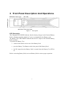
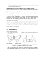
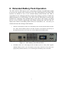
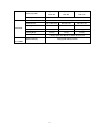
CONTENTS
1. Introduction ................................................................................................................2
2. Safety .......................................................................................................................2
3. Front Panel Description And Operations .........¡Error! Marcador no definido.
4. Rear Panel Description ...........................................................................................5
5. Installation.................................................................................................................6
6. Extended Battery Pack Operation ..........................................................................9
7. System Specifications ............................................................................................10
1
1. Introduction
The battery pack Rack/Tower Series of Products has been designed to provide quality
power protection at outstanding prices. The External Battery Packs have been
designed with removable battery cartridges and individual chargers for maximum
value.
2. Safety
IMPORTANT SAFETY INSTRUCTIONS: It is imperative to SAVE THESE
INSTRUCTIONS!
NOTE: Please read this manual before installing the 1KVA-3KVA battery pack,
model 1KVA battery pack, 2KVA battery pack, 3KVA battery pack as it provides
important safety information. Please follow the instructions contained herein during
installation, troubleshooting and maintenance of the battery packs. If questions exist
after reading this manual, please contact the Customer Service or Technical Support.
This Symbol indicates “ATTENTION”
This Symbol indicates “RISK of Electrical Shock”
Φ
This Symbol indicates “Alternating Current Supply Phase”
This Symbol indicates “Alternating Current Supply”
This Symbol indicates “Direct Current Supply”
This Symbol indicates “Equipment Grounding Conductor”
CAUTION! It is required, when using the AC cords attached to the Battery Packs,
that a two pole, three wire grounded AC wall outlet be utilized. The receptacle and
branch protection must comply with local electrical codes.
CAUTION! These Battery Packs must be installed and operated in a temperature
controlled environment (0-40 degrees Celsius). Place the Battery Packs and UPS in a
location or area that will provide maximum air flow (100mm sides and back).
WARNING: These Battery Packs contain potentially hazardous voltages. Do not
attempt to disassemble the Battery Pack beyond the battery replacement procedure. A
2
user should never attempt to service a Battery Pack, as they contain no user
serviceable parts. Battery replacement and repairs must be performed by Power or
Qualified Service Personnel, only. WARNING!! Risk of Electrical Shock exists.
Components contained within the Battery Packs may be energized from the battery
even when the AC input is disconnected.
De-energization of the Battery Packs
CAUTION! To de-energize the Battery Pack:
1. If the UPS is on, press and release the “Off” button.
2. Disconnect the UPS and the Battery Packs from the wall outlets.
3. Turn off the DC breaker on the rear panels of the Battery Packs.
4. Disconnect the battery cable from the rear panel of the UPS.
5. For complete Battery Pack de-energization, disconnect the batteries.
WARNING: Qualified Service Personnel ONLY must perform the Installation and
Servicing of these Battery Packs.
Please Note: Each UPS has different DC bus voltages and each UPS is designed to
mate with a specific Battery Pack. Only use the specific Battery Pack, stated below,
with its appropriate UPS. These Battery Packs MUST be operated with their
respective UPS models, see the table below:
Model
UPS Model
1KVA battery pack
2KVA battery pack
3KVA battery pack
24 VDC
48 VDC
72 VDC
1KVAS
2KVAS
3KVAS
Warning! If an incorrect battery pack is connected to a UPS, a severe electrical
hazard may happen. Please always verify the Battery Pack model and the correct DC
bus voltage before connection
PLEASE SAVE THE PACKING MATERIALS!
CAUTION:
It is very critical to connect the correct voltage battery pack with
the UPS intended.
1KVA battery pack is for 1KVA UPS
2KVA battery pack is for 2KVA UPS
3KVA battery pack is for 3KVA UPS
CONNECTING THE INCORRECT BATTERY PACK TO THE UPS MAY
RESULT IN DAMAGE TO THE UPS AND/OR BATTERY PACK, AND THE
WARRANTY WILL BE VOIDED.
All battery packs have a different DC voltage configuration intended only for the
UPS listed above.
3
3. Front Panel Description And Operations
Figure 1
Front panel
LED Description
The Charging LED GREEN indicates that the battery charger in the External Battery
Pack is charging normally with the AC power cord attached to the Battery pack.
The Battery Test LED GREEN indicates that the DC output of the External Battery
Pack is normal.
To perform the Battery Test.
• switch on the breaker on the rear of the Battery Pack
•
press the Battery Test Button on the front panel of the Battery Pack
•
the DC output from the Battery Pack is normal when the Battery Test LED is
on
Before connecting Battery Pack, test each Battery Pack to assure proper operation.
4
4. Rear Panel Description
1KVA Battery pack rear panel
Figure 2
1KVA Battery pack rear panel
2KVA/3KVA Battery pack rear panel
Figure 3
2KVA/3KVA Battery pack rear panel
1. The DC Circuit Breaker connects and disconnects the DC bus voltage from the
Battery pack to the UPS. The DC Circuit Breaker will disconnect in the event of
an over-current condition.
2. The External Battery connector is for Daisy Chaining additional Battery Packs
and/or connecting to the UPS.
3. The AC Inlet is for connecting the input power cord to operate the Charger.
4. The Input AC Breaker will disconnect in the event that the Internal Charger
draws excessive current.
5
5.
The External Battery cable is for connecting the Battery Pack to the UPS or Daisy
Chaining additional Battery Packs.
CONNECTING THE BATTERY PACK TO AN AC POWER SOURCE
Battery Packs require 220V input voltage, each socket permits only three battery
packs’ input power cord to be plugged in.
1. Connect the Battery Pack input power cord into the AC inlet on the Battery Pack.
2. Insert the “plug” end of the input power cord for the Battery Pack into the AC wall
outlet. Only utilize a two-pole, three-wire grounded receptacle. Do not use additional
cords, outlet strips or surge strips.
3. Switch on the DC circuit breaker. At this point, the UPS will need to be started.
Please refer to the recommended process in the UPS User’s Manual. NOTE: If
connecting more than one Battery Pack please refer to the Daisy Chaining section.
CHARGING THE BATTERY
If the Battery Packs are plugged into an AC source and properly installed, the internal
batteries will be charged when acceptable voltage is provided. Battery Packs must be
charged for a minimum of 6 hours before use. NOTE: If the Battery Pack is going to
be out of service or stored for six months or above, the batteries must be recharged for
at least 36 hours every six months.
5. Installation
Plastic base installation
① two plastic base brackets
following Figure
Figure 4
② flatten it after intercrossing intercross as
1KVA Battery Pack plastic base assembly
③ 2KVA/3KVA Battery Pack plastic base assembly is similar to 1KVA Battery
Pack, the difference is that there is a 1U plastic base bracket extended board for
2KVA/3KVA Battery Pack.
6
Figure 5
2/3KVA Plastic base (A)
Figure 6
2/3KVA Plastic base (B)
Figure 7 2/3KVA Plastic base (C)
Figure 8 2/3KVA Plastic base (D)
2KVA/3KVA Battery Pack Cabinet installation bracket assembly
① screw A, screw B, two M4 screws ( symmetrical on both sides, a total of four)
Figure 9
Cabinet bracket assembly
② cabinet installation bracket screw hole A, screw hole B are respectively
corresponding to two screws (symmetrical on both sides, a total of four).
7
Figure 10 Cabinet installation bracket
Figure 11 Cabinet installation bracket
assembly
③ screw the two M4 screws described as Fig 9 ( symmetrical on both sides, a total of
four).
Figure 12
Cabinet installation bracket assembly
Tower/Rack assembly
Figure 13
Tower-mounted assembly
Figure 14
8
Rack-mounted assembly
6. Extended Battery Pack Operation
The 1KVA-3KVA UPS System can be connected to multiple extended battery packs
to increase the runtime when connected to the UPS supporting the load. Most UPS
Systems are limited to one or two external battery packs because the UPS is
responsible for the recharging and does not have the recharge capacity to handle the
additional batteries to a full recharge. The 1KVA-3KVA UPS System overcomes this
limitation by equipping each extended battery pack with its own charger, providing
the user a way to achieve significantly more battery backup time. Not all of the AC
input power cords for the Battery Pack need to be connected to AC - the more you
connect the faster the recharge of the batteries.
1. The DC Circuit Breaker on the rear of the Battery Pack connects and disconnects the DC
bus voltage from the Battery Pack to the UPS. The DC Circuit Breaker will also trip to
the OFF position in the event of an over-current condition in the Battery Pack.
Figure 15
1KVA Battery Pack REAR VIEW
2. The Battery Pack use a cable shipped with each Battery Pack to “daisy chain” together
additional Battery Pack to the first Battery Pack being connected to the UPS in the
appropriately labeled connector, or for connecting the first Battery Pack to the UPS.
9
Figure 16
Daisy chain
3. The input AC Circuit Breaker will trip to the OFF position in the event that the internal
Battery Pack charger draws excessive current.
7. System Specifications
EXTENDED BATTERY PACK
1KVA Battery
2KVA Battery Pack
MODELS
3KVA Battery Pack
Pack
Voltage
220 VAC
AC Current
0.5A
1A
1.5A
INPUT
Frequency
50/60 Hz
Input Protection
DC Voltage
Resettable Circuit Breaker
27.5 ±0.5V
55.0 ±0.5V
82.5 ±0.5V
CHARGER
DC Current
2.0A
Output Protection
Fuse
OUTPUT
BATTERY
Battery Type
sealed, maintenance free, valve regulated, lead acid
10
2 strings of (2) 12V
2 strings of (4) 12V
2 strings of (6) 12V
9 AH / 24V
9AH / 48V
9 AH / 72V
Battery Type (EBP)
Recharge Time
8 hours to 90%
Dimensions
W x D x H (mm)
Unit Dimensions
440 x 380 x 86.5
440 x 520 x 131
440 x 520 x 131
Shipping Dimensions
607 x 514 x 170
607 x 654 x 210
607 x 654 x 210
17 kg
31.5 kg
41 kg
19.5 kg
34.3 kg
43.8 kg
PHYSICAL
Unit Weight
Shipping Weight
battery pack, User Manual, DC cable, AC input cord
Included in box
INDICATORS
LED Visual Display
Charging LED, Battery test LED
& ALARMS
11