1
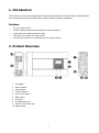
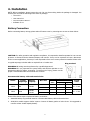
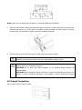
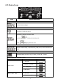
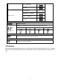
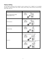
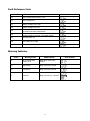
User Manual 2KVA-3KVA INVERTER Version: 1.01 Table Of Contents 1. Introduction ................................................................................................................................................. 1 Features ........................................................................................................................................................... 1 2. Product Overview ........................................................................................................................................ 1 3. Safety Instructions...................................................................................................................................... 2 4. Installation ................................................................................................................................................... 3 Battery Connection .......................................................................................................................................... 3 AC Output Connection ..................................................................................................................................... 4 5. OPERATION .................................................................................................................................................. 5 Power ON/OFF ................................................................................................................................................ 5 Operation and Display Panel ........................................................................................................................... 5 LCD Display Icons ........................................................................................................................................... 6 LCD Setting ...................................................................................................................................................... 7 Display Setting ................................................................................................................................................. 9 Operating Mode Description .......................................................................................................................... 10 Fault Reference Code .................................................................................................................................... 11 Warning Indicator ........................................................................................................................................... 11 6. SPECIFICATIONS ....................................................................................................................................... 12 7. TROUBLE SHOOTING ................................................................................................................................ 13 Appendix: Approximate Back-up Time Table ........................................................................................... 14 1. Introduction This is inverter can offer uninterruptible power support with portable size. Its comprehensive LCD display offers user-configurable and easy-accessible button operation based on different applications. Features Pure sine wave inverter Isolation design between input and output for safety guarantee Lightweight and anodised aluminum casing Low power consumption for energy saving Overload/ DC reverse/ Over temperature/ short circuit protection 2. Product Overview 1. LCD display 2. Status indicator 3. Fault indicator 4. Function buttons 5. Power on/off switch 6. Battery input 7. AC output 8. Communication port 9. Remote on/off control port 10. GND Terminal 1 3. Safety Instructions WARNING: This manual contains important safety and operating instructions. Read this manual carefully before installations and operations, keep it for future reference. 1. Before using the unit, read all instructions and cautionary markings on the unit, the batteries and all appropriate sections of this manual. 2. Do not disassemble the unit. Take it to a qualified service center when service or repair is required. Incorrect re-assembly may result in a risk of electric shock or fire. 3. To reduce risk of electric shock, disconnect all wirings before attempting any maintenance or cleaning. Turning off the unit will not reduce this risk. 4. CAUTION – Only qualified personnel can install this device with battery. 5. Be very cautious when working with metal tools on or around batteries. A potential risk exists to drop a tool to spark or short circuit batteries or other electrical parts and could cause an explosion. 6. Please strictly follow installation procedure when you want to disconnect DC terminals. Please refer to INSTALLATION section of this manual for the details. 7. GROUNDING INSTRUCTIONS -Inverter should be connected to a permanent grounded wiring system. Be sure to comply with local requirements and regulation to install. 8. NEVER cause AC output and DC input short circuited. 9. Warning!! Only qualified service persons are able to service this device. If errors still persist after following troubleshooting table, please send this inverter back to local dealer or service center for maintenance. 2 4. Installation NOTE: Before installation, please inspect the unit. Be sure that nothing inside the package is damaged. You should have received the following items inside of package: The unit x 1 User manual x 1 Communication cable x 1 Software CD x 1 Battery Connection Before connecting battery wirings, please take off bottom cover by removing two screws as shown below. CAUTION: For safety operation and regulation compliance, it’s requested to install a separate DC over-current protector or disconnect device between battery and inverter. It may not be requested to have a disconnect device in some applications, however, it’s still requested to have over-current protection installed. Please refer to typical amperage in below table as required fuse or breaker size. Ring terminal: WARNING! All wiring must be performed by a qualified personnel. WARNING! It's very important for system safety and efficient operation to use appropriate cable for battery connection. To reduce risk of injury, please use the proper recommended cable and terminal size as below. Recommended battery cable and terminal size: Model Typical Amperage 2KVA 66A 3KVA 100A Battery capacity Wire Size Cable mm2 Ring Terminal Dimensions D (mm) L (mm) 1*6AWG 14 6.4 29.2 2*10AWG 8 6.4 23.8 100AH 1*4AWG 22 6.4 33.2 200AH 2*8AWG 14 6.4 29.2 100AH Torque value 2~ 3 Nm 2~ 3 Nm Please follow below steps to implement battery connection: 1. Assemble battery ring terminal based on recommended battery cable and terminal size. 2. 2KVA/3KVA model supports 24VDC system. Connect all battery packs as below chart. It’s suggested to connect at least 100Ah capacity battery. 3 NOTE: Please only use sealed lead acid battery or sealed GEL/AGM lead-acid battery. 3. Insert the ring terminal of battery cable flatly into battery connector of inverter and make sure the bolts are tightened with torque of 2-3 Nm. Make sure polarity at both the battery and the inverter is correctly connected and ring terminals are tightly screwed to the battery terminals. 4. Fixing the bottom cover on the unit by two screws, refer to the picture in step 1. WARNING: Shock Hazard Installation must be performed with care due to high battery voltage in series. CAUTION!! Do not place anything between the flat part of the inverter terminal and the ring terminal. Otherwise, overheating may occur. CAUTION!! Do not apply anti-oxidant substance on the terminals before terminals are connected tightly. CAUTION!! Before making the final DC connection or closing DC breaker/disconnector, be sure positive (+) must be connected to positive (+) and negative (-) must be connected to negative (-). AC Output Connection Connect the load to the output sockets. 4 5. OPERATION Power ON/OFF Once the unit has been properly installed and the batteries are connected well, simply press On/Off switch to turn on the unit. The unit will work automatically. When press the switch again, the unit will be turned off. Operation and Display Panel The operation and display panel, shown in below chart, is on the front panel of the inverter. It includes three indicators, four function keys and a LCD display, indicating the operating status and input/output power information. LCD display LED indicators Function keys LED Indicator LED Indicator Green Red Messages Flashing Output is powered in inverter mode. Solid On Fault occurs in the inverter. Flashing Warning condition occurs in the inverter. Function Keys Function Key Description ESC To exit setting mode UP To go to previous selection DOWN To go to next selection ENTER To confirm the selection in setting mode or enter setting mode 5 LCD Display Icons Icon Function description Input Source Information Indicate battery voltage. Configuration Program and Fault Information Indicates the setting programs. Indicates the warning and fault codes. Warning: Fault: flashing with warning code. lighting with fault code Output Information Indicate output voltage, output frequency, load percent, load in VA and load in Watt. Battery Information Indicates battery level by 0-24%, 25-49%, 50-74% and 75-100%. Battery capacity be presented as below. Load Percentage Battery Voltage LCD Display < 1.717V/cell 1.717V/cell ~ 1.8V/cell Load >50% 1.8 ~ 1.883V/cell > 1.883 V/cell < 1.817V/cell 50%> Load > 20% 1.817V/cell ~ 1.9V/cell 6 1.9 ~ 1.983V/cell > 1.983 < 1.867V/cell 1.867V/cell ~ 1.95V/cell Load < 20% 1.95 ~ 2.033V/cell > 2.033 Load Information Indicates overload. Indicates the load level by 0-24%, 25-50%, 50-74% and 75-100%. 0%~25% 25%~50% 50%~75% 75%~100% Mode Operation Information Indicates the DC/AC inverter circuit is working. Mute Operation Indicates unit alarm is disabled. LCD Setting After pressing and holding ENTER button for 3 seconds, the unit will enter setting mode. Press “UP” or “DOWN” button to select setting programs. And then, press “ENTER” button to confirm the selection or ESC button to exit. 7 Setting Programs: Program Description Selectable option Escape 00 04 Exit setting mode Power saving mode enable/disable Saving mode disable If disabled, no matter connected load (default) is low or high, the on/off status of inverter output will not be effected. Saving mode enable If enabled, the output of inverter will be off when connected load is pretty low or not detected. Restart disable 06 Auto restart when overload occurs (default) Restart disable 07 09 18 19 Auto restart when over temperature occurs Restart enable Restart enable (default) 50Hz (default) 60Hz Alarm on (default) Alarm off Return to default If selected, no matter how users display screen switch display screen, it will (default) automatically return to default display Output frequency Alarm control screen (Input voltage /output voltage) Auto return to default display screen after no button is pressed for 1 minute. Stay at latest screen If selected, the display screen will stay at latest screen user finally switches. Backlight on 20 Backlight control (default) Record enable 25 Backlight off Record Fault code 8 Record disable (default) Display Setting The LCD display information will be switched in turns by pressing “UP” or “DOWN” key. The selectable information is switched as below order: battery voltage, output voltage, output frequency, load percentage, load in Watt, load in VA. Selectable information LCD display Battery voltage=25.5V, output voltage=230V Battery voltage/Output voltage (Default Display Screen) Battery voltage=25.5V, Output frequency=50Hz Output frequency Battery voltage=25.5V, Load percentage=70% Load percentage When connected load is lower than 1kVA, load in VA will present xxxVA like below chart. Load in VA When load is larger than 1kVA (≧1KVA), load in VA will present x.xkVA like below chart. 9 When load is lower than 1kW, load in W will present xxxW like below chart. Load in Watt When load is larger than 1kW (≧1KW), load in W will present x.xkW like below chart. Operating Mode Description Operation mode Standby mode / Fault mode Description LCD display No output is supplied by the unit. The unit will provide output Battery Mode power from battery and PV power. 10 Power from battery. Fault Reference Code Fault Code Fault Event 01 Fan is locked when inverter is off. 02 Over temperature 03 Battery voltage is too high 04 Battery voltage is too low 05 06 Icon on Output short circuited or over temperature is detected by internal converter components. Output voltage is abnormal. (For 1K/2K/3K model) Output voltage is too high. (For 4K/5K model) 07 Overload time out 08 Bus voltage is too high 09 Bus soft start failed Warning Indicator Warning Code Warning Event Audible Alarm 01 Fan is locked when inverter is on. Beep three times every second 03 High battery Beep once every second 04 Low battery Beep once every second 07 Overload Beep once every 0.5 second 11 Icon flashing 6. SPECIFICATIONS INVERTER MODEL Rated Output Power 2KVA 3KVA 2KVA/1.6KW 3KVA/2.4KW Output Voltage Waveform Pure Sine Wave Output Voltage Regulation 230Vac± 5% Output Frequency 50Hz Peak Efficiency 90% Overload Protection 5s@≥150% load; 10s@110%~150% load 2* rated power for 5 seconds Surge Capacity Nominal DC Input Voltage 24Vdc Cold Start Voltage 23.0Vdc Low DC Warning Voltage @ load < 20% 22.0Vdc @ 20% ≤ load < 50% 21.4Vdc @ load ≥ 50% 20.2Vdc Low DC Warning Return Voltage @ load < 20% 23.0Vdc @ 20% ≤ load < 50% 22.4Vdc @ load ≥ 50% 21.2Vdc Low DC Cut-off Voltage @ load < 20% 21.0Vdc @ 20% ≤ load < 50% 20.4Vdc @ load ≥ 50% 19.2Vdc High DC Recovery Voltage 29Vdc High DC Cut-off Voltage 31Vdc No Load Power Consumption <20W Saving Mode Power Consumption <10W Operating Temperature Range 0°C to 55°C Storage temperature -15°C~ 60°C Dimension (D*W*H), mm 369 x 232 x 82 Net Weight, kg 4.3 12 7. TROUBLE SHOOTING Problem Unit shuts down automatically during startup process. No response after power on. LCD/LED/Buzzer Explanation / Possible cause LCD/LEDs and buzzer will be active for 3 seconds and then complete off. The battery voltage is too low (<1.91V/Cell) 1. Charge battery. 2. Replace battery. No indication. 1. The battery voltage is far too low. (<1.4V/Cell) 2. Battery polarity is connected reversed. Fault code 07 Overload error. The inverter is overload 110% and time is up. 1. Check if batteries and the wiring are connected well. 2. Charge battery. 3. Replace battery. Reduce the connected load by switching off some equipment. Check if wiring is connected well and remove abnormal load. Check whether the air flow of the unit is blocked or whether the ambient temperature is too high. Check if spec and quantity of batteries are meet requirements. Output short circuited. Fault code 05 Buzzer beeps continuously and red LED is on. What to do Fault code 02 Temperature of internal converter component is over 120°C. Internal temperature of inverter component is over 100°C. Fault code 03 The battery voltage is too high. Fault code 01 Fan fault Replace the fan. Fault code 06 Output abnormal (Inverter voltage below than 190Vac or is higher than 260Vac) 1. Reduce the connected load. 2. Return to repair center Fault code 08/09 Internal components failed. Return to repair center. 13 Appendix: Approximate Back-up Time Table Model 2KVA 3KVA Load (VA) Backup Time @ 24Vdc 100Ah (min) Backup Time @ 24Vdc 200Ah (min) 200 766 1610 400 335 766 600 198 503 800 139 339 1000 112 269 1200 95 227 1400 81 176 1600 62 140 1800 55 125 2000 50 112 300 449 1100 600 222 525 900 124 303 1200 95 227 1500 68 164 1800 56 126 2100 48 108 2400 35 94 2700 31 74 3000 28 67 Note: Backup time depends on the quality of the battery, age of battery and type of battery. Specifications of batteries may vary depending on different manufacturers. 14