1
MTC-2 and ACU User Manual V3.2
MTC-2 mini tank controller with ACU auxiliary control unit
MTC-2 can work alone as a twin motor ECS (electronic speed controller) for RC tanks. When the ACU
(auxiliary control unit) is connected, it can also control turret rotation, gun elevation, gun firing, machine
gun firing and engine sounds. When the GSU (gun stabilize unit) is connected, ACU can stabilize gun
elevation and turret rotation. For GSU operation, see separate GSU manual.
MTC-2 highlight features:
-
MTC-2 can work alone as a twin motor ESC, with 8A continuous current for 130 to 380 size motors.
-
ECS with forward, reverse, left, right and pivot turn over all speed range.
-
5, 4 or 2 channel receiver options. When using 2 channel receivers, control can be switched
between tank motion and turret / gun motion by trimmer action.
-
Simple one button setup procedure.
-
Voltage range 4.8V – 7.4V
-
Auto shutdown at low battery
-
Dimension (PCB): 31 x 38 x 20mm (1.2” x 1.5” x 0.8”)
ACU highlight features:
-
Three servo ports for turret rotation, gun elevation and gun barrel recoil.
-
Support optional GSU (gun stabilize unit). See separate GSU manual for details.
-
Main gun led and machine gun led flashes.
-
22KHz high quality digital sound effects, including main gun sound, machine gun sound and engine
sound.
-
Engine sound includes engine start, stop, idle, and running. Engine sound changes according to
speed. Engine sound can be turned off by jumper.
-
Turret rotation can be replaced by gun left/right motion by jumper setting.
-
Gun return to reload position after fire (can be disabled by jumper).
-
ACU size 38 x 25 x 12mm (1.5”x1”x0.5”)
Contents
MTC-2 parts
ACU parts
Typical MTC-2 and ACU connections
Transmitter Stick Modes
Using MTC-2 for the First Time
4CH Setup Procedures
2CH Setup Procedures with Turret Control
2CH Control Mode Switching
2CH Setup Procedures without Turret Control
Setup Gun Reload Position
Reset to Factory Settings
Track Motion Control
Turret Motion Control
3
3
4
5
5
5
6
6
7
7
7
8
8
Copyright 2012
www.35rctank.com
Page 1
MTC-2 and ACU User Manual V3.2
Engine Sound Control
Input Voltage
Troubleshooting
9
9
9
RC receiver connectors
3
4
5
+ -
L
MTC-2 Jumper settings
V
shutdown voltage setting
with jumper - shutdown at 6V
no jumper - shutdown at 3.3V
T
turn mode
with jumper - pivot turn enabled
no jumper - pivot turn disabled
R
gun auto reload
with jumper - gun return to reload
position after fire
no jumper - auto reload disabled
gun turret type
with jumper - 360deg turret
no jumper - fixed turret
G
R
V
T
R
G
Led indicator
Setup button
ACU
J1
J2
Speaker volume
adjust
GF
MF
ACU Jumper settings
J1 engine sound on/off
with jumper - engine sound on
no jumper - engine sound off
SP
J2 reserved
MF
GF
SMK
ROT
REC
ELV
GF gun fire enabled
MF machine gun fire enabled
GF gun fire disabled
MF machine gun fire disabled
ACU Connectors
PWM(white)
+V(red)
GND(black)
2
GND(top)
GND(top)
GND(top)
1
MF - machine gun fire led connector (gnd on top)
GF - gun fire led connector (gnd on top)
SP - speaker connector (gnd on top)
SMK (upper) - reserved
ROT (upper) - turret
rotation servo connector
ELV (lower) - gun elevation
servo connector
REC (lower) - gun recoil
servo connector
Fig.1 - MTC-2 and ACU auxiliary control unit
Copyright 2012
www.35rctank.com
Page 2
MTC-2 and ACU User Manual V3.2
MTC-2 parts:
1) Battery connector – 4.8 – 7.4V battery input. DO NOT REVERSE INPUT POLARITY TO AVOID
DAMAGE! Remove battery when not in use for long time.
2) RC receiver connectors – for 4 CH receivers, connect all connectors No.1 – 4. For 2 CH receivers,
connect connectors No.1 and 2 only. CH5 is used for GSU on/off if GSU is connected.
3) Led indicator – multi-purpose indicator. When power on, it lights up 1 sec and then blinks slowly if it
do not receive RC signal. It lights up continuously when signal is received from the RC connectors. It
will also flash during the setup process. See setup procedures for details.
4) Setup button – setup MTC-2 for a particular transmitter. It also setup the gun reload position if R
jumper is on. See setup procedures for details.
5) V jumper – shutdown voltage setting. With jumper installed, the shutdown voltage is set at 6V. When
the jumper is removed, the shutdown voltage is set at 3.3V. See the input voltage section for more
details.
6) T jumper – turn mode jumper. Remove this jumper to disable pivot turn.
7) R jumper – enable gun return to reload position after fire. Remove this jumper to disable this feature.
8) G jumper – gun motion select jumper. Install this jumper for turret with 360o rotation. In this mode, a
servo modified for continuous rotation is connected to ROT port to control turret rotation speed.
When the jumper is removed, a standard servo is connected to ROT port to control the left/right gun
movement.
ACU parts:
9) ROT port – turret rotation servo port. A continuous rotation servo is connected here to control turret
rotation. For tanks with fixed turret, remove the G-jumper to set this port to left / right gun movement
by standard servo.
10) ELV port – gun elevation servo port.
11) REC port – gun recoil servo port.
12) Speaker volume adjust – trimmer to change speaker volume.
13) SP port – speaker port, for driving 8Ohm / 1W speaker.
14) GF port – gun flash led port.
15) MF port – machine gun flash led port.
16) J1 jumper – remove jumper to turn off engine sounds.
17) GF and MG jumpers – for enable/disable of gun fire and machine gun fire. See Fig.1 for jumper
settings.
Copyright 2012
www.35rctank.com
Page 3
MTC-2 and ACU User Manual V3.2
Notes:
7.2V NiMH Battery Pack
1) To reduce interference, solder 1uf capacitors between two
power leads, and 0.1uf capacitors between power leads and
motor case.
2) DO NOT REVERSE BATTERY POLARITY TO AVOID
DAMAGE!!
3) Disconnect battery when not in use for long time.
4) For 2CH receivers, use connectors No.1, No.2.
5) CH5 is used for GSU on/off control.
6) See appendix A for modifying servos to continous rotation.
280
motor
L
280
motor
R
+
+
0.1uF capacitors
(Note1)
1uf capacitors
(Note1)
Power switch
Note2 Note3
Antenna
L
R
2-5CH Receiver Note4 Note5
Futaba
R156F
6/B
5
4
3
2
1
40MHZ
V
T
R
G
MTC-2
+
Turret rotation servo (Note6)
resistor
ACU
Gun flash led
+
Machine gun flash led
resistor
J1
J2
GF
MF
Gun elevation servo
+
Gun recoil servo
-
MF/GF/ SP: top cable GND
8Ohm/0.5W speaker
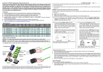
Fig.2 - Typical MTC-2 and ACU connection
Copyright 2012
www.35rctank.com
Page 4
MTC-2 and ACU User Manual V3.2
Transmitter Stick Modes
The stick mode of MTC-2 is shown in Fig.3. If your transmitter has a different stick mode, change the
connector numbers accordingly.
4 CH control
2 CH control
CH1 - track turning
CH2 - track speed
CH1 - track turning,
turret rotation
CH2 - track speed,
gun elevation
and firing
CH3 - gun elevation
and firing
CH4 - turret rotation
Fig.3 - Stick modes of MTC-2
Using MTC-2 for the First Time
When using MTC-2 for the first time, or when you change the transmitter, you must perform the setup
procedures to store the transmitter characteristic in MTC-2. To avoid unintended track motion,
disconnected motors or remove tracks during setup.
4CH Setup Procedures
Step 1 - Power on the transmitter.
The led indicator will light up. With
all sticks and trimmers at centre,
press the seup button once. The
led indicator will start flash.
Led
Indicator
Step 2 - Move both sticks to four
extreme positions slowly. The
sequence of move is not important.
Led
Indicator
Step 3 - Press setup button again.
Led indicator will stop flash. The
setup procedures is completed.
Led
Indicator
Copyright 2012
www.35rctank.com
Page 5
MTC-2 and ACU User Manual V3.2
2CH Setup Procedures with Turret Control
Step 1- Power on the transmitter. The led
indicator will light up. Move both sticks to
centre. Move left trimmer to middle. Move
right trimmer to leftmost position. Press the
setup button once. The led indicator starts
flash.
Led
Indicator
Step 2 - Move both sticks to extreme
positions slowly. The sequence of move is
not important.
Led
Indicator
Step 3 - With both sticks back to centre,
move right trimmer to rightmost position.
Led
Indicator
Step 4 - Press the setup button again. Led
indicator stop flashs. The setup procedures
is completed. After setup, control will go to
turret and gun motions. See following
section for control mode switching.
Led
Indicator
2CH Control Mode Switching
When using 2CH transmitters, you can either control track or turret motions. You can switch between the
two modes as follows:
Switch control to turret
- With both sticks at centre, move right
trimmer quickly to rightmost position.
Fast
Switch control to track motion
- With both sticks at centre, move right
trimmer quickly to leftmost position.
Fast
Notes
- Speed is critical in mode switching. The trimmer must be moved quickly.
- If switching failed, you can either repeat the process, or you can power off
and on the transmitter. MTC-2 will determine the control mode when
transmitter is power on.
Copyright 2012
www.35rctank.com
Page 6
MTC-2 and ACU User Manual V3.2
2CH Setup Procedures without Turret Control
MTC-2 can be setup to control track motion only. All turret motions and sound effects will be disabled.
Step 1- Power on the transmitter. The led
indicator will light up. Move both sticks and
trimmers to centre. Press the setup button
once. The led indicator starts flash.
Led
Indicator
Step 2 - Move both sticks to extreme
positions slowly. The sequence of move is
not important.
Led
Indicator
Step 3 - Press the setup botton again. Led
indicator stops flash. The setup procedures
is completed.
Led
Indicator
Setup Gun Reload Position
When R jumper is on, gun will return to reload position after gun fire. To setup the gun reload position,
move gun to the desired reload position and then press the setup button. You can go through the setup
process as usual, or you can press the setup button at once to end setup.
Reset to Factory Settings
MTC-2 is factory set to 4CH control. To reset to factory settings, press and hold the setup button until it
stop flash. MTC-2 is then reset.
Copyright 2012
www.35rctank.com
Page 7
MTC-2 and ACU User Manual V3.2
Track Motion Control
Forward
Reverse
Pivot
Turn
Right
Turn
Pivot
Turn
Left
Turn
Pivot
Turn
Pivot
Turn
4CH Transmitter
Forward
Reverse
Pivot
Turn
Right
Turn
Pivot
Turn
Left
Turn
Pivot
Turn
Pivot
Turn
2CH Transmitter
-
Pivot turn begins when right stick move halfway left or right
-
Pivot turn is disabled when T-jumper is removed (Fig.1).
Turret Motion Control
Turret
Rotation
Turret
Rotation
Gun
Elevation
Slow
Gun
Firing
Fast
Machine
Gun
Firing
Fast
4 CH Transmitter
-
Gun
Elevation
Gun
Firing
Machine
Gun
Firing
Slow
Fast
Fast
2 CH Transmitter
To trigger gun firing, move right stick (left stick for 2CH transmitter) quickly from middle to top. Tank
will recoil during gun fire. After gun fire, move stick back to middle to resume operation.
-
To trigger machine gun firing, move right stick (left stick for 2CH transmitter) quickly from middle to
bottom. Machine gun sound continuous when stick keep at bottom. Move stick back to middle to
resume operation.
-
Both sound effects can be disabled by jumper settings (Fig.1).
Copyright 2012
www.35rctank.com
Page 8
MTC-2 and ACU User Manual V3.2
Control of Engine Sound
Engine sound will be generated when ACU is connected and J1 installed:
Engine start – trigger by first throttle
Engine idle and running – engine sound changes according to speed
Engine stop – with throttle at center, hold turning stick at left or right extreme position for 5 sec.
Alternatively, engine will stops in 5 sec after transmitter is turned off.
T h ro ttle
T u rn
K e e p th ro ttle a t c e n tre , h o ld
tu rn in g s tic k a t le ft o r rig h t
e x tre m e fo r 5 s e c .
E n g in e s to p b y s tic k m o tio n
Input Voltage
-
MTC-2 is designed to work at 4.8 - 7.4V (4 - 6 cell 1.2V NiMH, or 2 cell Lipo battery). To avoid over
discharge of Lipo battery, it will shutdown automatically when input voltage is too low. After shutdown,
the motors will stop and led indicator flashes slowly. Also, the ACU beeps if connected.
-
The V jumper determines the shutdown voltage. When installed, the shutdown voltage is set at 6V. It
is suitable for 2 cell Lipo. When the V jumper is removed, the shutdown voltage is set at 3.3V. It is
suitable for NiMH and 1C Lipo.
-
When using 4 cell NiMH or 1C Lipo, operation becomes unstable when input voltage drops below 4V.
This may happens before auto shutdown and you should replace the battery.
-
When using Lipo battery, follow all safety precautions for Lipo battery. Always disconnect battery
after use.
Troubleshooting
Symptom
Cause
Resolution
Led blinks when tank Motor interference
- Add noise filtering capacitors (Fig.2)
moves
- Keep antenna away from motors cables
Low battery
Tank out of control
- Prevent loose metal contacts
- Motor fault, replace motor
- Replace or recharge battery
Led indicator not
Antenna problems
stable, or turns off
- Check antenna length
- Keep antenna in vertical position
- Keep antenna away from motors cables
Led indicator dims
Low battery
- Replace or recharge battery
Cannot trigger main
Improper setup
- Do setup again
gun / machine gun
Wrong jumper setting
- Check GF, MF jumpers
when tank moves
Copyright 2012
www.35rctank.com
Page 9