1
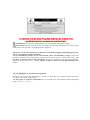
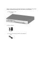
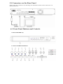
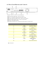
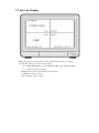
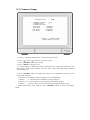
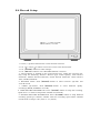
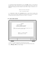
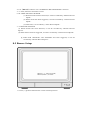
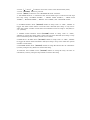
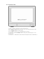
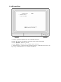
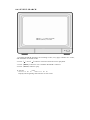
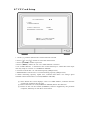
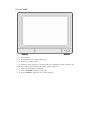
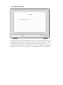
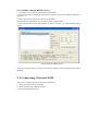
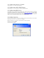
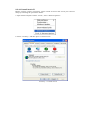
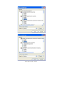
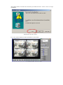
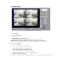
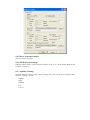
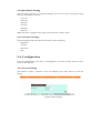
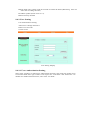
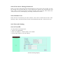
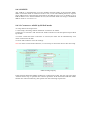
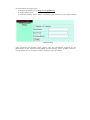
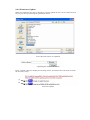
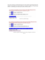
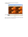
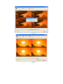
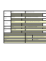
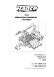
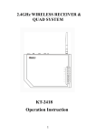
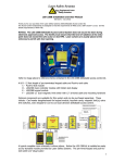
4CH MJPEG DVR
USER MANUAL
INDEX
1. SAFETY PRECAUTIONS.....................................................................3
2. INTRODUCTION..................................................................................4
2.1 PRODUCT INTRODUCTION..........................................................4
2.2 APPLICATION..............................................................................4
3. FEATURES............................................................................................5
4. PACKING LIST.....................................................................................6
5. INSTALLATION...................................................................................7
5.1 CONNECTORS ON THE REAR PANEL..........................................7
6. NAME and FUNCTION of EACH PART............................................8
6.1 FRONT PANEL BUTTONS AND CONTROLS.................................8
6.2 REAR PANEL BUTTONS AND CONTROLS...................................10
7. OPERATING PROCEDURE................................................................11
7.1 POWER ON.................................................................................11
7.2 MONITORING MODE..................................................................11
7.3 RECORD DISPLAY......................................................................12
7.4 PLAYBACK DISPLAY..................................................................13
7.5 NOTE!.........................................................................................14
8. SYSTEM SETUP...................................................................................15
8.1 MENU..........................................................................................15
8.2 SYSTEM SETUP............................................................................16
8.2.1 TIME SET................................................................................17
8.2.2 PASSWORD SET....................................................................18
8.2.2.1 PASSWORD CHANGE........................................................19
8.3 CAMERA SETUP............................................................................21
8.3.1 CAMERA SETTING................................................................23
8.4 RECORD SETUP............................................................................24
8.4.1 RECORD MODE.....................................................................25
8.5 BUZZER SETUP............................................................................26
8.5.1 SENSOR TYPE:......................................................................28
8.6 EVENT LIST.................................................................................29
8.6.1 TIME SEARCH.......................................................................30
8.6.2 EVENT SEARCH....................................................................31
8.7 CF CARD SETUP..........................................................................32
8.7.1 SELECT TIME........................................................................33
8.7.1.1 COPY....................................................................................34
8.7.2 FORMAT/ ERASE..................................................................35
8.8 HARD DRIVE SETUP....................................................................36
8.8.1 HDD FORMAT:......................................................................37
9. REMOTE CONTROL (Optional)...........................................................38
9.1 NETWORK DVR SETUP...............................................................38
9.2 CONNECTING NETWORK DVR....................................................39
9.3 MAIN DISPLAY.............................................................................44
9.3.1 LIVE DISPLAY...........................................................................44
9.3.7 QUALITY SETTING....................................................................47
9.3.8 RESOLUTION SETTING..............................................................48
9.3.9 ADVANCE SETTINGS.................................................................48
9.4. CONFIGURATION.........................................................................48
9.4.1 SYSTEM SETTING......................................................................48
9.4.2 USER SETTING...........................................................................49
9.4.2.1 USER AUTHORIZATION SETTING...........................................49
9.4.2.2 NEW USER/ CHANGE PASSWORD..........................................50
9.4.2.3 DELETE USER........................................................................50
9.4.3 NETWORK SETTING..................................................................50
9.4.3.1 FIXED IP................................................................................50
9.4.3.2 DHCP....................................................................................51
9.4.3.3 CONNECT TO ADSL BY PPPOE MODE..................................51
9.4.4 DDNS SETTING........................................................................52
9.4.5 FIRMWARE UPDATE.................................................................54
10. CF Card/ HDD Player Software Description........................................56
11. TROUBLESHOOTING........................................................................62
12. SPECIFICATIONS...............................................................................63
The author assumes no responsibility for any errors or omissions that may appear in this
document nor does it make a commitment to update the information herein.
2005/08/08, Ver.: 0.1, P/N: 040111
1. SAFETY PRECAUTIONS
It is advised to read the Safety Precaution Guide through carefully before
operating the product, to prevent any possible danger.
WARNING: Alert the user to the presence of un-insulated “dangerous voltage”.
CAUTION: Alert the user the presence of important operating and maintenance (Servicing)
instructions in the literature accompanying the appliance.
The power cord is the main power connection. Constantly plugging and unplugging of the
power cord might result in cord failure.
Do not install the product in an environment where the humidity is high. Unless the
product is waterproof or weatherproof, otherwise poor image quality or failure may occur. Do
not drop or subject them to physical shocks. Except for vandal-proof or shockproof product,
otherwise failure may occur. Never subject product to direct strong light. Damage may
occur.
Do not spill liquid of any kind on the product.
If it gets wet, wipe it dry immediately. Alcohol or beverage can contain minerals that may
corrode the electronic components.
Do not expose to extreme temperatures. Use of DVR in an environment within temperature
range of -10∘ C ~ +50∘ C.
2. INTRODUCTION
2.1 Product Introduction
World leading technology not only perfect for office safety, personal home security,
public environments, industry surveillance, schools, and so on. Quick and simple
installation, the best choice for your own ultimate protection.
This state-of-art 4-channel digital recording system, equipped with advanced embedded
CPU operating system, powerful MJPEG compression technology. A standalone type DVR
system that is based on an embedded OS, replacing the conventional VCR. This userfriendly surveillance System can be operated by the control pads on the front panel, use of
time and event to select playback of recorded materials, efficient live recording and
playback functions, convenient CF card function that supports backup of HDD, and the
ease of a removable HDD (may be swapped with a like HDD). Password protection on
remote viewing and access. What more can you expect!
2.2 Application
Security:
ATM (auto teller machine), bank, gas station, shop and parking lot.
Factory/ Office:
Factory, warehouse, remote technology support, conference room, and outdoor parking
lot.
Education/ Military/ Government Organization:
Important facilities, areas, rapid transit system, and railroad safety.
Recreation/ Activities:
Sports and news broadcast.
Home:
Elevator, doorway, community safety, and hotels.
Hospital/ Kindergarten:
Hospital and isolated ward, home for the aged, kindergarten, and baby nourishing
center.
3. FEATURES
Auto video input detection
Auto detects video input (NTSC/ PAL) and supports combined use of color and b/w
cameras.
Supports high quality digital video recording
Use of M-JPEG compression technology (NTSC: 30fps/ PAL: 25fps).
Video Resolution
• NTSC: 640x 224
• PAL: 640x 272
Monitor Resolution
• NTSC: 720x 480
• PAL: 720x 576
Replaces the conventional VCR.
Stores video on HDD instead of VCR tapes. Large disk capacity, (Tested with Seagate
400GB HDD)
Built-in motion detection function.
Motion detection sensitivity rate may be setup under motion detection function.
Highly efficient event recording, saving storage capacity.
Motion detection function enables recording only when system detects motion, thus
increases the amount of time available for recording.
Easy access to the desired record.
Time & date search supports instant retrieval of images and alarm event search
Makes searching simpler.
Data can be stored on CF card.
Cards inserted in the CF card slot makes it easier to back up recordings and transfer
images to a PC.
Removable hard disk tray.
Removable hard disk drive allows you to backup important data with ease.
Live monitoring through internet from anywhere (optional).
Built-in TCP/ IP network interface (auto detects and switches to 10/ 100Base T).
4. PACKING LIST
Check to make sure all of the items shown below are included in your product
package. If something is missing, contact your dealer as soon as possible.
(1) DVR (digital video
recorder)
(2) Power adapter
(3) Power Cord (Plug type differs depending on
area)
5.1 Connectors on the Rear Panel
Please setup the connection by following the illustration shown below (network is an
optional function):
5. INSTALLATION
6.1 Front Panel Buttons and Controls
1. Removable HDD tray
2. Front Panel Button Definition
(2) QUAD
Press this button for quad screen
(3) Ch 1
Press this button to display channel 1 (one)
(4) Ch 2
Press this button to display channel 2 (two)
(5) Ch 3
Press this button to display channel 3 (three)
(6) Ch 4
Press this button to display channel 4 (four)
(7) Seq
Press this button for sequence display of all channels in full screen
(8) Menu
Press this button to access menu (must stop record to alter setup)
(9) Enter
Press this button to accept or confirm data input
(10) Up/left
Press this button to move cursor up or down.
(11) Down/right Press this button to move cursor right or left.
(12) Rec LED
LED lights while recording( flashes on and off)
(13) Play LED
LED lights during playback.
(14) Menu LED
LED lights upon entering setup menu.
(15) Stop LED
LED lights when entering stop mode.
(16) Record
Press this button to start/stop record.
(17) Stop
Press to stop playback and return to live mode.
(18) Pause
Press to pause or freeze playback.
(19) Rewind
Press to view reverse playback.
(20) Play
Press to access search and playback.
(21) F.F.
Press to playback in fast forward( must be in play mode)
(22) CF Card slot Use compact flash card
6.2 Rear Panel Buttons and Controls
(1) RJ45: Internet connection terminal (optional).
(2) Video Input [VIDEO IN]: Connect to cameras.
(3) DC 12V (4A) [Power Input terminal]: power socket.
(4) S-Video Output [S-VIDEO OUT]: Connect to the monitor.
(5) Video Output [VIDEO OUT]: Connect to the monitor.
(6) Video Loop [VIDEO LOOP].
(7) I/O Block [I/O BLOCK]: Terminal function description is shown below.
No.
Name
1
GND
2
ALARM 1
3
GND
4
ALARM 2
5
GND
6
ALARM 3
7
GND
8
ALARM 4
9
N.O.
10
COM
11
NC
(8) Cooling Fan.
Function
Ground
Terminal(signal)
Alarm Input Terminal
Ground
Terminal(signal)
Alarm Input Terminal
Ground
Terminal(signal)
Alarm Input Terminal
Ground
Terminal(signal)
Alarm Input Terminal
Alarm Output (Normal
Open)
Alarm Output
Terminal (NC/ NO
COM)
Alarm Output (Normal
7. OPERATING PROCEDURE
7.1 Power On
After power on, DVR will auto-detect its peripherals (self-testing, warm-up, auto detects
the hard disk and starts CF-card testing, and etc.)
The system will detect the video input and judge whether the video system is NTSC or
PAL. When video input is unable to be detected (VIDEO LOSS), the system will send out
an alarm, press any button to stop the alarm (it will not affect the actual recording).
7.2 Monitoring Mode
This mode is a default for our system after power on. Under this mode, system supports
live view for monitoring. Press《REC》button, the system enters the record mode,
press《PLAY》button to start playback, press《MENU》button to enter the menu setup
display. During record or playback, press《STOP》button to stop the current activity and
returns to monitoring mode. Under main menu, press《MENU》 to return to monitoring
mode.
During playback, press《STOP》button to return to monitoring mode. Press again to
change the speed (FF1, FF2 or FF3), or press《REW》button to start reverse playback.
To reset (under quad or single display), press《PAUSE》button 5 times, the
message《ALL SETTING DATA IS INITIALIZED.》will be displayed by flashing 3
times, and after reset the password will be set as default value (111111).
When reset procedure has been completed, the message“DVR RESET COMPLETED.
TURN OFF AND ON THE DVR"will be displayed, then please restart the DVR.
7.3 Record Display
Note:CH1: No block figure next to CH1 indicates that it is not recording.
EACH: Record Type QUAD: Record Type
(T): TIMER RECORD (A): ALARM RECORD (M): MIX RECORD
(□ ): Currently under recording.
VIDEO LOSS: Video input unable to be detected.
CAMERA1: Name for CH 1.
OFF: Channel is set to “OFF”.
7.4 Playback Display
1. First press《STOP》button to stop record, then press《PLAY》button to enter
search display.
2. Press《FF》button, then《PLAY》button to playback data from earliest
recorded data to most recent. Use《↑ 》and《↓ 》button to move the cursor to the
desired playback time, press《PLAY》button to start playback.
3.
To
view
recorded
videos
of
a
specific
time,
use《FF》button,《↑ 》or《↓ 》button, and 《ENTER》button to make changes.
4. During playback press《PAUSE》button to pause and press《PLAY》button to play.
5. Press《FF》button to fast-forward playback.
6. Press《REW》button to reverse playback.
7. Press《STOP》button to stop playback.
7.5 Note!
1. “Auto Sequence” function operates only during recording or under live status (Dwell
Time: 5 seconds). Sequencing will bypass a channel with video loss if programmed
accordingly (Example: Video Loss occurs on CH3, sequencing order:
CH1→ CH2→ CH4→ QUAD).
2. To deactivate “Auto Sequence” function, press 1, 2, 3, 4, or QUAD.
3. Withdrawing the CF card, each time before the system (DVR) enters recording or
playback status, it will auto detect the hard disk (detection time is about 5 to 30seconds).
4. When copying data from the hard disk to a CF card, make sure that the data has been
completely copied onto the CF card, before withdrawing it from the slot. Otherwise, an
error may occur, system will display “CF CARD REMOVED”, and auto returns to live
display.
5. Camera name can only be viewed during recording and live display.
PASSWORD SETUP
>
PASSWORD
CHANGE
MENU
PASSWORD
STOP REC
PASSWORD
■■■
OFF
OFF
CAMERA SEUP
>
CAMERA
SELECT
RECORD
ENABLE
MOTION
DETECTION
MOTION
SENSITIVITY
HUE
CONTRAST
BRIGHTNESS
■■■
CH1
ON
ON
03
08
08
08
RECORD SETUP
>
RECORD TYPE
VIDEO QUALITY
TIME RECORD
FRAMERATE
MOTION RECORD
FRAMERATE
SENSOR RECORD
FRAMERATE
ALARM REC TIME
RECORD MODE
■■
EACH
NORMAL
04
15
15
10
BUZZER SETUP
>
■■
ALARM
ALERT
VIDEO LOSS
ALERT
HDD FULL
ALERT
BUZZER
TIME
RELAY OUT
TIME
SENSOR
TYPE
ON
ON
ON
05
05
SENSOR SETUP
>
CHANNEL-1
CHANNEL-2
CHANNEL-3
CHANNEL-4
■■ ■
NOT
INSTALLED
NOT
INSTALLED
NOT
INSTALLED
NOT
INSTALLED
TIME SEARCH
■■ ■
05/01/13 19:27:16
BEGIN TIME:
05/01/13
END TIME:
19:27:16
05/01/15
15:00:06
■■■
EVENT SEARCH
BEGIN:
END:
05/01/15 15:00:01
>
05/01/15 15:00:06
01 ALARM
2005/01/15
02 MIX
15:00:01
2005/01/15
03 TIME
14:00:01
2005/01/15
04 ALARM
13:00:01
2005/01/15
12:00:01
SELECT TIME
>
■■■
DAY
BEGIN TIME
15:00:01
END TIME
15:00:06
COPY
05/01/15
■■■■
(1)
SELECT
(2)
DATA:10MB
ESTIMATED
(3)
(4)
(5)
(6)
(7)
TIME:2 Minute
START COPY
CAPACITY IS NOT
ENOUGH
10% COPIED
PRESS (ENTER) TO
COPY
PRESS (MENU) TO
EXIT
HARD DRIVE SETUP
>
DISK FULL
HDD SIZE
HDD USED
HDD
FORMAT
■■
OVERWRITE
120103MB
13321MB
11%
8.
SYSTEM SETUP
8.1 Menu
(1)
(2)
(3) > SYSTEM SETUP
CAMERA SETUP
RECORD SETUP
BUZZER SETUP
EVENT LIST
CF CARD SETTING
HARD DRIVE SETUP
(4) PRESS (< >), THEN (ENTER)
PRESS (MENU) TO EXIT
■
:First Menu Layer (Main Menu)
■■
:Second Menu Layer
■■■
:Third Menu Layer
■■■■
:Fourth Menu Layer
(1) MAIN MENU: Item subject (First menu layer does not have a subject).
(2) Menu Layer Indication: The device consists of four menu
layers.
(3) Menu Operation and Setup
Press《← 》or《→ 》button to move the cursor ( > ).
Press《ENTER》button enter the sub menu.
Press《MENU》button:
Under second or third menu layer, the system will return to the previous menu layer (second
layer to first layer or third layer to second layer) and auto updates the modified data.
Under main menu (first menu layer), the system will enter live mode.
Press《ENTER》button, to increase or decrease the setting values that have been highlighted.
(4) Menu Layer Operation Guide
8.2 System Setup
SYSTEM SETUP
■■
> TIME SET
PASSWORD SET
LOARD DEFAULT
VERSION
V1.0
PRESS(< >), THEN (ENTER)
PRESS (MENU) TO EXIT
1. Cursor (>) position indicates the current function selected.
2. Press《← 》and《→ 》button to move the cursor.
3. Press《ENTER》button to proceed.
4. Press《MENU》button to exit “System Setup”.
5. “System Setup"is situated on the second menu layer. Under this menu layer user may
setup the system time, password, and return system to default value, etc (VERSION
displayed represents the FIRMWARE version).
8.2.1 TIME SET
TIME
■■■
2005/01/11 17:23:06
^
PRESS (< >), THEN (ENTER)
PRESS (MENU) TO EXIT
1. Cursor (^) position indicates the current time and date selected.
2. Use《← 》or《→ 》button to move the cursor.
3. Use《ENTER》button to setup time and date.
4. Use《MENU》button to exit “Time Setup”.
8.2.2 PASSWORD SET
PRESS (< >), THEN (ENTER)
PRESS (MENU) TO EXIT
1. Cursor (>) position indicates the current function selected.
2. Use《← 》and《→ 》button to move the cursor to the desired item .
3. Use《ENTER》button to make changes.
4. Use《MENU》button to exit “Password Setup”.
5. When the password is setup to “ON”, user will be requested to enter the correct
password for entering from live display to menu selection (Default Password:
111111).
6. When password is setup to “ON”, user will be requested to enter the correct
password to stop recording (Default Password: 111111).
8.2.2.1 PASSWORD CHANGE
■■■■
CURRENT PASSWORD :_ _ _ _ _ _
NEW
PASSWORD :_ _ _ _ _ _
CONFIRM PASSWORD :_ _ _ _ _ _
PRESS (MENU) TO EXIT
1. Press《ENTER》button to show the display above.
2. Enter the current password (CURRENT PASSWORD).
3. Enter new password (NEW PASSWORD).
4. Confirm the new password (CONFIRM PASSWORD).
5. When password change is successful, the system will display “PASSWORD
CHANGED”.
※ Default Value: 111111
If password entered is incorrect, you will receive a message “NO PASSWORD
CHANGED” to inform you (message flashes three times) and the system returns
to “Password setup” selection.
8.2.3 LOAD DEFAULT
■■■
PRESS (ENTER) TO RESET
PRESS (MENU) TO EXIT
1. Press《ENTER》button to show the display above.
2. Press《ENTER》button the message《ALL SETTING DATA IS INITIALIZED》 will
be displayed by flashing 3 times, and returns to default value. When reset procedure has been
completed, the message“DVR RESET COMPLETED TURN OFF AND ON THE
DVR"will be displayed, please restart the DVR.
3. Press《MENU》button to exit “Load Default Setup” selection.
8.3 Camera Setup
CAMERA SETUP
■■
> CAMERA ENABLE
1234
CAMERA TITLE
---CAMERA SETTING
CH1 TITLE
CAMERA1
CH2 TITLE
CAMERA2
CH3 TITLE
CAMERA3
CH4 TITLE
CAMERA4
PRESS (< >), THEN (ENTER)
PRESS (MENU) TO EXIT
1. Cursor (>) position indicates the current function selected.
2. Press《← 》and《→ 》button to move the cursor.
3. Press《ENTER》button to proceed.
4. Press《MENU》button to exit.
5. “Camera Setup” is situated on the second menu layer. Under this menu layer user
may setup camera name (camera name for CH1, CH2, CH3 and CH4), standard
camera setup, etc.
6. Press《ENTER》button to change the camera view combination (select to view
the desired channel).
(It consists of 16 different optional camera view combinations)
1) Select (- - - -), all cameras are disabled (no image display).
2) Select (1 2 3 4), all cameras are operational (quad image display).
3) Select (- - - 4), only camera four is operational (CH4 image display only).
7. When proceeding “CH1 TITLE”, press《ENTER》button to show the display
below:
V
CH1 TITLE
CAMERA1
12345678
“V” indicates the position of the cursor. Press《← 》and《→ 》button to move the
cursor, and press《ENTER》button to change the title (maximum 8 characters).
8. All channel titles are setup the same way.
Once the user formats the hard disk drive, the camera title returns to its default
setting (CAMERA1/ CAMERA2/ CAMERA3/ CAMERA4). It is because this setup
is stored in the hard disk drive.
8.3.1 CAMERA SETTING
PRESS (< >), THEN (ENTER)
PRESS (MENU) TO EXIT
1. Cursor (>) position indicates the current function selected.
2. Press《← 》and《→ 》button to move the cursor to the desired item.
3. Press《ENTER》button to make changes.
4. Press《MENU》button to exit “CAMERA SETUP” selection.
5. CAMERA SELECT: Press《ENTER》button to select the desired channel.
6. RECORD ENABLE: Press《ENTER》button to switch the channel recording ON/ OFF.
7. MOTION DETECTION: Press《ENTER》button to switch the motion detection
function ON/ OFF.
8. MOTION SENSITIVITY: Press《ENTER》button to setup the motion
sensitivity rate (5 sensitivity rate values, 01 most sensitive).
9. HUE: Press《ENTER》button to adjust the color of cameras (15 color
adjustment values, default value: 08 ).
10. CONTRAST: Press《ENTER》button to adjust the camera contrast (15
contrast adjustment values, default value: 08).
11. BRIGHTNESS: Press《ENTER》button to adjust camera brightness (15 color
adjustment values, default value: 08 ).
8.4 Record Setup
PRESS (< >), THEN (ENTER)
PRESS (MENU) TO EXIT
1. Cursor (>) position indicates the current function selected.
2. Use《← 》and《→ 》button to move the cursor to the desired item.
3. Use《ENTER》button to make changes.
4. Use《MENU》button to exit “RECORD SETUP” selection.
5. “Record Setup” is situated on the second menu layer. Under this selection user
may setup the following function: Record Type, Video Quality, Time Record
Framerate, Motion Record Framerate, Sensor Record Framerate, Alarm Record
Time, and Record Mode.
6. RECORD TYPE: Press《ENTER》button to select between “QUAD” and
“EACH” mode.
7. VIDEO QUALITY: Press《ENTER》button to select different quality
recordings (HIGH, NORMAL or LOW).
8. TIME RECORD FRAMERATE: Press《ENTER》button to setup the recording
speed when “T” mode is setup under schedule record mode.
9. MOTION RECORD FRAMERATE: Press《ENTER》button to setup different
recording speeds per channel, suitable when the recording speed under schedule
record mode is setup to “M” (mix) or “A” (alarm).
10. SENSOR RECORD FRAMERATE: Press《ENTER》button to setup different
recording speed, when a sensor device has been triggered (this setup is only active
when the recording speed under schedule record mode is setup to “M”(Mix) or “A”
(Alarm)).
NTSC:30,15,10,7,5,4,3,2,1fps.
PAL :25,12,8,6,4,3,2,1fps.
11. ALARM REC TIME: Press《ENTER》button to setup sensor recording time
after a sensor device has been triggered (this setup functions is only active when the
recording speed under schedule record mode is setup to “A”(Alarm)).
8.4.1 RECORD MODE
■■■
RECORD MODE
T: TIME A: MOTION+SENSOR
M: TIME+MOTION+SENSOR
V
< M A T T T T T T T T T T T T T T T T T T T T-T >
0 3 6 9 12 15 18 21 24
PRESS (< >), THEN (ENTER)
PRESS (MENU) TO EXIT
1. Cursor (V) position indicates the current function selected.
2. Use《← 》and《→ 》button to move the cursor to the desired item (time).
3. Use《ENTER》button to make changes.
4. Use《MENU》button to exit “SCHEDULE RECORD MODE” selection.
5. T: Time, indicates continuous record.
6. M: TIME+MOTION+SENSOR.
(1) When motion has been detected, it will be recorded by “Motion Record
Speed”.
(2) When sensor has been triggered, it will be recorded by “Sensor Record
Speed”.
(3) Otherwise, it is recorded by “Time Record Speed”.
7. A: MOTION+SENSOR
(1) When motion has been detected, it will be recorded by “Motion Record
Speed”.
(2) When sensor has been triggered, it will be recorded by “Sensor Record Speed”.
※ When both “MOTION” and “SENSOR” has been triggered, it will be
recorded by “Motion Record Speed”.
8.5 Buzzer Setup
PRESS (< >), THEN (ENTER)
PRESS (MENU) TO EXIT
1. Cursor (>) position indicates the current selected position.
2. Press《← 》and《→ 》button to move the cursor to the desired item (time).
3. Press《ENTER》button to proceed.
4. Press《MENU》button to exit “BUZZER SETUP” selection.
5. “BUZZER SETUP"is situated on the second menu layer. Under this menu layer
user may setup “ALARM ALERT”, “ VIDEO LOSS ALERT”, “ HDD FULL
ALERT”, “ BUZZER TIME”, “ RELAY OUT TIME”, and “ SENSOR TYPE”.
6. ALARM ALERT: Press《ENTER》button to setup “ON” or “OFF”, whether to
trigger the alarm when motion event has been detected (this setup is only active
when the system is under record status and schedule record is setup to “M”(Mix) or
“A” (Alarm)).
7. VIDEO LOSS ALERT: Press《ENTER》button to setup “ON” or “OFF”,
whether to trigger the alarm when video loss has been detected (this setup is only
active when the system is under record or live status).
8. HDD FULL ALERT: Press《ENTER》button to setup “ON” or “OFF”, whether
to trigger the alarm when hard disk is full (this setup is only active when the system
is under record status).
9. BUZZER TIME: Press《ENTER》button to setup the buzzer time to continuous
(CONT), and press any button to release this setup.
10. RELAY OUT TIME: Press《ENTER》button to setup the relay out time to
continuous (CONT), and press any button to release this setup.
8.5.1 SENSOR TYPE:
PRESS (< >), THEN (ENTER)
PRESS (MENU) TO EXIT
1. Cursor (>) position indicates the current selected position.
2. Press《← 》and《→ 》button to move the cursor to the desired item (CH1~CH4).
3. Press《ENTER》button to make changes.
4. Press《MENU》button to exit “SENSOR SETUP” selection.
5. CHANNEL-1: Press《ENTER》button to setup “NO” (Normal Open) or “NC”
(Normal Close).
6. CHANNEL-2 ~ CHANNEL-4: Please follow the setup shown above (CHANNEL-1).
8.6 Event List
EVENT LIST
■■
> TIME SEARCH
EVENT SEARCH
PRESS (< >), THEN (ENTER)
PRESS (MENU) TO EXIT
1. Cursor (>) position indicates the current function selected.
2. Press《← 》and《→ 》button to move the cursor to the desired item.
3. Press《ENTER》button to proceed.
4. Press《MENU》button to exit “EVENT LIST” selection.
5. “EVENT LIST"is situated on the second menu layer. Under this menu layer user
may setup “TIME SERACH” or “EVENT SEARCH”.
8.6.1 TIME SEARCH
PRESS (< >), THEN (ENTER)
PRESS (MENU) TO EXIT
1. TIME SEARCH: Displays system recording time (begin and end).
2. Press《← 》and《→ 》button to select the desired time and date.
3. Press《ENTER》button to setup playback starting time and date.
4. Press《MENU》button to exit “TIME SEARCH” selection.
5. Press《PLAY》button to play.
8.6.2 EVENT SEARCH
PRESS (< >), THEN (ENTER)
PRESS (MENU) TO EXIT
1. EVENT SEARCH: Displays all recording events, every page consists of 7 events,
and maximum 63 stored events.
2. Press《← 》and《→ 》button to select the desired event to playback.
3. Press《MENU》button to exit “EVENT SEARCH” selection.
4. Press《PLAY》button to play.
※ BEGIN:
END:
05/01/15 15:00:01
05/01/15 15:00:06
Displays the beginning and end time of each event.
8.7 CF Card Setup
CF CARD SETUP
■■
> COPY
FORMAT/ERASE
TOTAL CAPACITY
REMAINING CAPACITY
512MB
100MB
PRESS (< >), THEN (ENTER)
PRESS (MENU) TO EXIT
1. Cursor (>) position indicates the current function selected.
2. Press《← 》and《→ 》button to select the desired item.
3. Press《ENTER》button to proceed.
4. Press《MENU》button to exit “CF CARD SETUP” selection.
5.“CF CARD SETUP"is situated on the second menu layer. Under this menu layer
user may setup to “COPY” or “FORMAT/ ERASE”.
6. TOTAL CAPACITY: CF Card total capacity (MB per unit).
7. REMAINING CAPACITY: CF Card remaining capacity (MB per unit).
8. When remaining capacity equals zero, indicates that there’s no storage space
available. Please format the CF Card (FORMAT/ ERASE).
※ Note! When the screen displays “NO CF CARD EXIST”, indicates that the
system can not detect the CF-card.
※ Note! Format the CF card (FORMAT/ ERASE) before first time use.
※ Please do not use the format (FORMAT) function supplied by the personal
computer, data may be lost due to such action.
8.7.1 SELECT TIME
PRESS (< >), THEN (ENTER)
PRESS (MENU) TO EXIT
1. SELECT TIME: Displays the newest event date, begin and end time.
2. Press《← 》and《→ 》button to select the desired item.
3. Press《ENTER》button to setup the desired date and time to proceed copy
(COPY) function.
4. Press《MENU》button to exit “SELECT TIME” selection.
※ When the message “CF CARD FULL” is displayed on the screen, indicates
that storage capacity (CF Card) is full. Please format (FORMAT/
ERASE) to proceed.
※ When the message “Time Input Error” is displayed on the screen, indicates
that the time date entered is incorrect or no data. The system auto returns
to CF Card setup selection.
8.7.1.1 COPY
(1)Data capacity.
(2)Estimated time to complete data copy.
(3)Request to confirm copy.
(4)When the data capacity is greater than the remaining storage capacity, the
message “CAPACITY IS NOT ENOUGH” will be displayed.
(5)Data copy percentage completed.
(6)Press《ENTER》button to start copy.
(7)Press《MENU》button to exit “Copy Display”.
8.7.2 FORMAT/ ERASE
■■■
PASSWORD INPUT (6) :------
1. When proceeding with “FORMAT/ ERASE” function, the above display will be
shown.
2. When password entered is correct, the screen will display the message
“PASSWORD CORRECT”, “CF CARD FORMATED” (flashes 3 times), indicates
CF Card format is successful.
3. When password entered is incorrect, the screen will display “PASSWORD
INCORRECT” (flashes 3 times), and returns to “CF CARD SETUP” selection.
※ This password is the same to format hard disk.
8.8 Hard Drive Setup
PRESS (< >), THEN (ENTER)
PRESS(MENU)TOEXIT
1. Cursor (>) position indicates the current function selected.
2. Press《← 》and《→ 》button to select the desired item.
3. Press《ENTER》button to make changes or to proceed.
4. Press《MENU》button to exit “HARD DRIVE SETUP” selection.
5. “HARD DRIVE SETUP” is situated on the second menu layer. Under this menu
layer user may setup to overwrite or format the hard disk.
6. DISK FULL: Press《ENTER》button to setup “ON” or “OFF”, whether to
overwrite or stop recording when the hard disk is full.
7. HDD SIZE: Displays hard disk capacity.
8. HDD USED: Displays the capacity already used.
8.8.1 HDD FORMAT:
■■■
PASSWORD INPUT (6) :------
1. When proceeding with “HDD FORMAT” function, the above display will be shown.
2. When password entered is correct, the screen will display the message “HDD
FORMATTED” (flashes 3 times), indicates hard disk format is successful.
3. When password entered is incorrect, the screen will display “PASSWORD
INCORRECT” (flashes 3 times), and returns to “HARD DRIVE SETUP” selection.
9. REMOTE CONTROL (Optional)
9.1 Network DVR Setup
Before installing the Network DVR, you need to first setup an IP Address, connect it to
the ADSL Modem or LAN Hub, and use IPEdit.exe to test the DVR.
Note: Before using PPPoE and DDNS connection method, one must first setup an IP
Address (using IPEDIT.exe).
9.1.1 Online with DHCP Server
Use IPEDIT.exe to find the installed Network DVR. Select this Network DVR in the
Camera List Window. The default configuration will be shown on the right window. Update
the IP status.
Online with DHCP Server
9.1.2 Online without DHCP Server
1. Use IPEdit.exe to find the installed Network DVR.
2. The Internet DVR without IP allocated by DHCP will have a default IP Address of
169.254.1.13.
3. Select this Internet DVR on Camera List Window.
4. The default configuration will be shown on the right window.
5. Under DOS mode enter “IPCONFIG” to access Geteway, IP, and Netmask setting
values.
Online without DHCP Server
After the “Submit” button is clicked, the IP information of this Network DVR will be
updated.
9.2 Connecting Network DVR
There are 3 methods for connecting Network DVR:
1. Online using Intranet or Fixed IP
2. Online using ADSL (PPPoE) Router
3. Online using DDNS Server
9.2.1 Online using Intranet or Fixed IP
Setup similar to “9.1 Network DVR Setup” .
9.2.2 Online using ADSL (PPPoE) Router
Setup similar to “9.4.3.3 Connect to ADSL by PPPoE mode”.
9.2.3 Online using DDNS Server
The DDNS service provides the dynamic IP to users to gain access to resources
connected to the Internet via a cable or DSL connection. Once you’ve decided to apply
this function, please register your domain name at http://www.dyndns.org (this website
supports free service for registered users). Paid DDNS service is applied to long-term
users. For more information, please refer to “9.4.4 DDNS Setup”.
9.2.4 Online Connection
Start the Internet Explorer, enter the IP Address of the Network DVR into the Address
field, such as 192.168.1.31 or click twice on IPEdit.
Before connection, “User name” and “Password” will be requested:
Default User Name: admin
Default Password: 1234
9.2.4.1 Install ActiveX
Before entering remote connection, please install ActiveX and check your browser
setup by following the procedures below:
a. Open Internet Explorer under “Tools”, select “Internet Options”.
b. Select “Security”, and then press “Custom Level”.
Security -> Custom Level
Start-up ActiveX Control
The graphic below will show the first time you install ActiveX . Select “Yes” to accept
installation.
Download ActiveX Control
Live view will be displayed when installation is successful.
Live display under ActiveX mode
9.3 Main Display
○
1
○
○
○
3
4
2
Remote control DVR - Main Menu
○ 1 Live Display
○ 2 DVR Control Button
○ 3 Video Setup
○ 4 Configuration: Enter detail setup
Recording: Displays recording setup menu (for video recording).
Snapshot: Pop-up window displays live images, right mouse click to save.
Note: To view complete interface, PC resolution must be adjusted to 1024x768.
9.3.1 Live Display
View/ Make changes on image display
Rotate/ Make changes on image direction
Image Recording/ Record function setup
Save Current Picture/ Save the current image
Welcome! Administrator/ Display current user name
About/ Version description
Move the cursor inside the image range, right mouse click to display 9 function selections:
9.3.2 View
Two types of display method:
a. Resizable: Adjustable image size.
b. Actual size: The actual image
size.
9.3.3 Rotate
Four types of rotate settings:
a. Rotate 0: Default state
b. Rotate 180: Rotate the image by 180 degrees.
c. Flip horizontal: Image flips horizontally
d. Flip vertical: Image flips vertically
9.3.4 Image Recording
Image Recording Setup Display:
Save as JPEG: Save as picture file
Save as AVI: Save as AVI animation file
Save as JPEG:
No Limit: Unrestricted image storage (continuous).
Number: Image storage according to “number”.
Save interval: Image storage according to “1/10 second” (e.g.: Enter “10”, then 1 frame
is stored per second. Enter “50”, then 1 frame is stored in 5 seconds).
Size: Image storage according to “size”.
Time: Image storage according to “time”.
Save Path: Image storage according to “Save Path”.
Pre Name: Image storage according to “Prefix Name”.
Save as AVI:
No Limit: Unrestricted image storage (continuous).
Number: Image storage according to “number”.
Save interval: Image storage according to “1/10 second” (e.g.: Enter “10”, then 1 avi
file is stored per second. Enter “50”, then 5 avi files are stored in 5 seconds).
Size: Image storage according to “size”.
Frame Rate: Image storage according to “frame rate”.
Time: Image storage according to “time”.
Maximum Number of Frame in Each File: Image storage according to “maximum frame”.
Save Path: Image storage according to “Save Path”.
Pre Name: Image storage according to “Prefix Name”.
9.3.5 Save Current Picture
Select to save live images.
9.3.6 DVR Control Setup
Supports DVR remote control function (Please refer to 6-1 Front Panel Buttons and
Controls, on page 8).
9.3.7 Quality Setting
Network DVR provides 5 image quality settings. The user can select the quality setting
from the “Quality” list box.
Highest
High
Medium
Low
Lowest
9.3.8 Resolution Setting
Network DVR provides six resolution settings. The user can select the quality setting
from the “Resolution” list box.
176x144
160x120
320x240
352x288
640x480
704x576
Note: The device supports auto video system detection (NTSC/ PAL).
9.3.9 Advance Settings
Network DVR provides the advanced settings for the following:
Brightness
Contrast
Saturation
Hue
9.4. Configuration
Only the administrator can select “Configuration”; the user account does not have
access to this function.
9.4.1 System Setting
The number on Port 1 and Port 2 may be changed, press “OK” button to save the
setting.
System Setting Display
Reboot DVR: The system needs 20 seconds to reboot the DVR (Rebooting does not
effect the recording function).
FirmWare update (Please refer to 6.7).
ReStore Factory Default
9.4.2 User Setting
User Authorization Setting
Add User or Change Password
Delete User Account
Current Users
User Setting Display
9.4.2.1 User Authorization Setting
Select item “Needed” to enable user authorization function, then each time before login
to Network DVR the Login window will request for “Username” and “Password”. To
disable user authorization function, select item “No Need”.
9.4.2.2 New user/ Change Password
Enter a new user name and password information to create a new user account, or enter
an existing user account, then set a new password to replace the old password, and
select “OK” to create the account or change password. After selecting “OK” button, the
“Current User List” would display the newly created user account.
9.4.2.3 Delete User
Enter the user account that you wish to delete, click “OK” to delete the account. After
selecting “OK”, the selected user account will be deleted from the “Current User List”.
9.4.3 Network Setting
9.4.3.1 Fixed IP
To setup follow the steps below:
1. Select item “Manually”.
2. Enter “IP Address”, “Subnet mask”, and ”DNS”.
3. Click “OK” button to save the setting.
Network Setting Display
9.4.3.2 DHCP
The “DHCP” is automatically set as the default network setting of the Network DVR.
When a Network DVR is connected to the LAN, it will issue DHCP packets to request
an IP address that is dynamically assigned by the DHCP server. If it is unable to get a
DHCP address on a limited number of tries, the Network DVR will assign a default IP
address such as “169.254.1.13”.
9.4.3.3 Connect to ADSL by PPPoE mode
To setup follow the steps below:
1. After setup, rebooting enables automatic connection to ADSL.
2. Enter the “Username” and “Password” fields with the account and password provided
by the ISP.
3. If item “Send mail after connected” is selected, the mail will be automatically sent
when connected to the ISP.
4. Click “OK” button to save the settings.
Note: In order to activate the function, it is necessary to reboot the device after the setup.
1
2
ADSL Setting Display
If the Network DVR and ADSL modem are connected by a hub, the user can select item
“Dial On Power Up” to perform the connect operation. If the Network DVR and ADSL
modem are connected directly, then please note the following steps below:
1. Power off Network DVR.
2. Connect Network DVR directly to the ADSL modem (using RJ-45 Ethernet port).
3. Power-up Network DVR.
4. Network DVR start dialing.
5. Once connected, mail the IP address information to the preset e-mail address.
6. After 10 times of connection failure, it aborts the operation and the user can reconnect
it by LAN to find the cause.
Note: If item “Send mail after connected” is selected, then the Network DVR will send a
mail that contains the message “Dial Up IP Address/ Netmask/ Gateway/ DNS Server”
will be mailed to the preset e-mail address.
Connection Message Send to User
9.4.4 DDNS Setting
Press “DDNS” server connection to start the function. It can autonomously and
automatically contact DDNS provider service whenever the router detects that its public
IP address has changed. The router logs on to an account you setup and maintain, and
updates the account with its latest public IP address. You may register at DDNS Server:
http://www.dyndns.org.
To setup follow the steps below:
1. Register at DDNS Server: http://www.dyndns.org.
2. Apply domain name.
3. Click the “Enable” button. Enter “UserName” and “Password” with “DomainName”.
DDNS Setting
After registering the domain name, please enter the information supplied by the
administrator to the Network DVR DDNS Account Setting. Select “Enable” button to
start-up DDNS server, and press “Submit” button to save the setting.
9.4.5 Firmware Update
When new firmware (bin file) is supplied, you may update the new version firmware (bin
file) to your PC by following the procedures below:
Select the Firmware to be Updated
Uploading the Selected Firmware
Press “Upload” button to display the message below, and follow the instruction to make
the necessary setup.
(1)
(2)
Firmware Update
Press “here” button (1) to update Firmware. Press “here” button (2) to delete the file. The
message below displays the writing progress of the firmware update. When Firmware
update is completed, it will show 100%, and a message “Click here to reboot DVR
browser” will be displayed, requesting to restart the Network DVR.
Firmware Update Display
Firmware Update Completed, you will be prompted to restart the
device.
10. CF Card/ HDD Player Software Description
PC Player Software
System Requirement
※ OS (Operating System) Windows 2000/ XP or later.
※ Use your PC to install DirectX (version DirectX 7.0 or above).
※ Using remote control software, please setup the resolution to 1024x768
or above.
Hardware Requirement
※CPU- 1.0 GHz or higher.
※RAM- 256 Mbyte or higher.
1. Installation
A. Hardware Installation
Make sure that HDD or CF card is connected through IDE or USB interface to the PC.
B. Software Installation
1. During installation, you will need a desktop or laptop computer that meets these
minimum requirements: Windows 2000 or XP.
2. Copy the PC Player Software to your PC (under any directory, e.g.: C:\ ). When user
starts the PC Player Software, it will auto create a directory “_config”, the purpose is to
store all parameter setup files supplied by the PC Player Software.
2. Operation
Move the cursor to the PC Player Software and double left mouse click to proceed. When
starting the PC Player Software, it auto-detects the CF card or HDD (about 1 min. to auto
detect, and may differ depending on file size).
※
Network DVR does not support player
software other then PC Player software.
3. Software Playback Interface Description
A. User Interface
Play System
System Status
Figure 1
When the system detects stored materials (HDD or CF card), the above graphic
(Figure 1) will be shown. User may operate the function buttons to make necessary
playback adjustment or store recordings onto the PC.
:
:
:
:
:
:
:
:
No
Recording
Materials
Stored
Fast
Rewind
Rewind
:
:
Back One
Frame
Pause
:
Playback
Forward
Forward
:
One Frame
Quad split
Fast
:
screen
Forward
display
CH2 Full
CH1 Full
:
Screen
Screen
Display
Display
CH4 Full
CH3 Full
:
Screen
Screen
Display
Display
Click this button to capture images as BMP file, graphic
shown by “Figure 2”will be shown and PC Player
Software auto creates a storage content “Capture MYS”.
:
※
Recording
Material
Stored
When recording videos onto the PC, first click the
“Pause” button, then “Now Recording” button on the
graphic shown by “Figure 3”. Click again to stop
recording (shown on the graphic by “Figure 4”) and the
PC Player Software auto creates a storage content
“Capture MYS”.
Note! Maximum storage capacity is 700MB, PC Player Software will
create one or more files to continue record (e.g.: Recorded video is 30
min. and capacity is 1000MB > 700MB. Therefore, the system will
store the recorded material into 2 files: one file (700MB) and the other
file (300MB)).
Click this button to playback recorded materials (stored
:
on PC), graphicshow by “Figure 5” will be displayed.
Please select the file to playback, press “open” to
playback. This button function is similar to “File
Player”function.
:
Click this button to shut the system.
Figure 2
Figure 3
Figure 4
Figure 5
B. Parameter Setup
To setup the parameter, click “Application set” button to show the graphic display
below (Figure 6):
Figure 6
11. TROUBLESHOOTING
Question
Why can’t the device read the hard disk?
Why can’t the device read the CF card?
Suggested HDD Brand
Suggested CF card Brand
Answer
Reinstall the hard disk, make sure that it is properly
connected, and reboot the device.
Reinsert the CF card, make sure that it is properly
connected and reboot the device.
Maxtor, Seagate, and Hitachi (System tested with
400GB).
Apacer, Sandisk, Transcend, Hagiware, A-DATA
and Silicon.
※CF Card Notice!
After inserting the CF card into the CF card slot on the front panel of the DVR, status LED will
be lit (orange). Enter menu, select“CF card setting"function to detect the CF card, and to
display the total capacity and remaining capacity. Error may occur when using certain brands.
When error occurs, the message“HDD R/W IS NOT READY"or“HARD DISK FAIL"will be
displayed, informing that the total capacity and remaining capacity displayed is incorrect.
If an error is encountered, please note the following:
1. After inserting the CF card into the CF card slot on the front panel of the DVR. Please wait
for 30 seconds (when the status LED goes off (orange) before starting CF card detection
or backup function.
2. During recording, do not insert the CF card, recording errors may occur.
3. Inserting the CF card during recording, may result in recording errors. Please reboot the
DVR and when the message“RECOVER HDD"appears, press “ENTER"button to repair
the previously recorded video.
Please take note on the condition mentioned above.
12. SPECIFICATIONS
Format
Video
Compression
Input
Output
Resolution
Display
Frame Rate
Division
Resolution
Recording
HDD
Frame Rate
Quality
Mode
Format
Removable
Input/ Output
Alarm
Trigger Mode
Function
Post Alarm
Search Method
Internet
Backup Device
Power Supply
NTSC/EIA or PAL/CCIR
Modified M-JPEG
4CH, BNC
1 x BNC, 1 x S-Video
720 x 480 (NTSC), 720 x 576 (PAL)
Max. 120/100 fps (NTSC/PAL)
Single, Quad, Sequence
Max. 640 x 244 (NTSC), 640 x 272 (PAL)
Max. 30/25 fps (NTSC/PAL)
High / Normal / Low
Manual / Schedule / Alarm / Motion Detection
1 x 3.5” IDE HDD (Max. 400GB)
1 x HDD RACK
4/ 1
Motion Detection, Sensor Input
Recording, Relay Output, Sound Alert
5~30sec
By Date, Time, Event
10/100BaseT Ethernet(RJ45)
CF-Card, HDD,
VCR
CF-Card, HDD, VCR,
TCP/IP network(live & playback)
Dimension (W*H*D)
DC 12V / 4A
4kg (without
4.1kg(with HDD)
HDD)
430mm x 320mm x 80mm
Operating Environment
30 ~ 80% RH, 5゚C ~ 40゚C (41゚F ~ 104゚F)
Weight