1
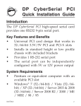
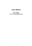
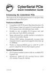
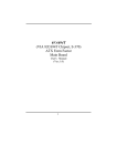
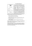
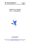
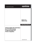
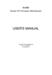
6086N2 V2.0 SET TOP BOX 6086N2 VIA C3 SERIES GCT-ALLWELL TECHNOLOGY, INC. User's Guide GCT-ALLWELL TECHNOLOGY, INC. 14321 Don Julian Road City of Industry, CA 91746 Phone 626-968-1116 • Fax 626-968-1131 URL:www.gctglobal.com URL: http://www.allwell.tv e-mail: [email protected] Specification Metallic 6086N2 / STB 6086N2 / STB6086N2 -CF VIA Eden 667 MHz Main Processor VIA Ezra 800-933 MHz series processor (Future Model) -64 MB SDRAM, 3.3V SDRAM support only -Two 168-pin DIMM socket Memory -Max of 512 MB with 256Mb SDRAM technology, support PC100/133 SDRAM -Non-Parity -TVIA CyberPro 5005 - Graphics Accelerator - Multi format Alpha blending -64 bit DRAM interface optimized for SGRAM 512 x 32 up to 4MB -2x ITU-BT656, ITU-BT601 8bit video input interface, one from EM8400 (VP-A), one Graphics Processor from DVBS (VP-B) (on board) -6 on chip DACS provide simultaneous S-Video, comp osite and RGB/SCART output or simultaneous VGA and TV output (S-Video and composite or RGB/SCART) - 3 Video windows plus PIP -Color key, Chroma key, DirectDraw & Mpeg-1 playback -NTSC 640 x 480 @ 60 Hz, -PAL 800x600/720x540/640x480 @ 50Hz -VIA VT8601A PLE133 North Bridge -Support PC100/133 SDRAM -Support up to 5 PCI master -VIA VT82C686B -PC99 Compliant PCI-to-ISA Bridge -Integrated super I/O -Ultra DMA 33/66/100 master mode PCI-EIDE Controller -USB x 2 South Bridge -Serial port x 2 (internal) -FDD Controller -Integrated keyboard controller with PS2 mouse -M-System DOC2000 socket supports + Foot print support TSOP 16M/32Mx2 -DiskOnModule support LAN communications -Two Realtek RTL8100B 10/100 Mb PCI - Supports Home Gateway 1 IR Interface Yes Audio/Video Switch -STV6412A audio/video switch matrix (Optional) for SCART -I2 C control -VIA VT1611A audio codec with 3D Audio Codec -AC97 2.1 compliant codec -Legacy audio SBPRO compatible Drive Bay 2 x 3.5" device (Metallic6086N2 model) OnBoard IDE 2 x Ultra DMA33 Floppy Disk Connector Desktop type Microphone Board Two 6.1mm phone jacks -Award BIOS with APM BIOS -DIP 2Mb flash w/ boot block supported -Power management support APM1.2, ACPI 430mm x 320mm x 80mm (WxDxH, Matellic6086N2 model) Box Dimension 340mm x 274mm x 60 mm (WxDxH, STB6086N2 model) Power Supply ATX 77W; 5V, 12V, 100-264 V auto switching Software Supported Microsoft Win95,Win 98, NT, WinCE, RTOS QNX, Citrix, Linux -D-sub 15 pin VGA connector -Dual Stacked SCART connector (European) -CBVS composite out (RCA jack yellow) -Audio out port (RCA jack white,red) -S-Video (4-pins DIN) Rear Panel -SPDIF output (RCA jack orange) -Two LAN ports (RJ-45) -Dual stacked USB port -6-pin mini DIN connector in PS/2 keyboard and PS/2 mouse, require auto detection between IR K/B -3.5mm mini phone jack x 1 for microphone input -Dimension 220mm x 242mm Board Form Factor -4 layer PCB, 6 mil minimum trace width and spacing -All components in primary side DVD ROM (optional) support EIDE DVD ROM Support two 3.3V PCI slots (Metallic 6086N2 Model) Riser Card Support one 3.3V PCI slot (STB 6086N2 Model) 2 -Sigma Designs EM8400 MPEG-2 video decoder -Embedded 80 mips RISC-Core -Full compliant with ISO 13818-2 main profile at main level MPEG-2 MPEG-2 Decoder -CCIR 656 supported resolution of 720x480 at 30 fps(NTSC) and 720x576 at 25 fps (Optional on Riser card) (PAL) -Support ISO 11172 MPEG-1 data stream -SPDIF output Technical Specification After plugging in the STB, two LED lights on the front of the STB will turn on. The green light labeled Power comes on immediately, indicating that the STB is receiving power. The yellow light labeled Transfer indicates that the STB has made a connection. This yellow light will blink anytime the STB is downloading. The 3 rd LED is can be programmed through GPIO address. 3 The Infrared Sensor does not light up. It receives signals from the Remote Control and Keyboard. Always make sure that there is a clear path between the Remote Control and the Infrared Sensor devices to ensure that the STB signals are unobstructed. Technical Specification IMPORTANT § Do not expose the STB to water or operate in a damp environment. § Do not use the power cord with an outlet or extension cord that does not allow both prongs to be fully inserted. § Do not overload power outlets. § Do not place the STB in direct sunlight or near a heat source. § Do not allow anything to rest on or roll over the power cord. § Unplug STB during a lighting storm. § Do not put or allow anything to fall into the STB unit. § Do not place anything on top of the STB unit, especially: § Liquid (drinks, etc.) § Flammable items (clothes, papers, etc.) Any object that may obstruct airflow through the vents (Books, magazines, other electrical components, such as a VCR, etc.) 4 Board Diagram 5 Major Components U14: Semtech SC1164 CPU DC/DC PWM IC U1: VIA C3 EBGA CPU DIMM1 and DIMM2: DIMM Socket support PC-133 U23: ST STV6412 Audio/Video Switch Matrix U2: VIA VT8601 U25: IGS CyberPro 5005 VGA (Building TV OUT) U13: TPA122 Op Amp for Audio Output U12: VIA VT1611A AC97 Codec U8: ICS 9248DF-39 Clock Generator U17/U18: IR keyboard controller U15/U16: RS-232 Buffer U29: VIA VT82C686B U10: DOC address Decoder U19/U21: Realtek RTL8100/8100B LAN control Chip U11: BIOS U9: DOC SL1: The PCI and PCI Riser U26/U27: VGA Memory Jumpers description IR Controller Resistor on RN88 PS/2 Keyboard/Mouse Resistor removed from RN88 PS/2 and IR Keyboard/Mouse Note: Both DIP and SMD IR keyboard controller IC was layouted in the board. Be sure the IR firmware version match with your remote ir keyboard controller J2 External SMI switch (Reservation Purpose for engineering testOnly) Open Disable Close Enable JBAT1 CMOS Clear Jumper Pin 1-2 Normal Operation Pin 2-3 Clear CMOS 6 Connectors description CN13 S-Video Connector Pin 1 GND Pin 2 GND Pin 3 Chrominace Pin 4 Luminance Note: The CN13 include a Luminance and Chrominace singals for general TV system which support better video quality than CVBS (composite) CN14. The CN14 is RCA Jack Connector. POWER1 Power Supply Connector Pin 1 VCC Pin 2 VCC Pin 3 +12 V Pin 4 -12 V Pin 5 GND Pin 6 GND Pin 7 5VSB Pin 8 PS-ON Note: There is no powergood signal from the power supply. The on-board U24 LP3470 will generate the powergood signal to the reset circuit of MB6086. JFAN1 CPU Fan Connector Pin 1 CPUFAN1 Pin 2 +12 V Pin 3 GND Note: The CPUFAN1 is a input pin to motherboard which supports the CPU Fan speed detect. There is no FAN on/off control for the CPU FAN CN9 Dual Scart Video/Audio Input/Output Connector( Note: The RCA and SCART is mutually exclusive) Program the U23 video/audio switch to RGB signal to SCART connector JP2 CRT/TV Select Pin 1-2 CRT Pin 2-3 TV 7 JP3 TV Mode select Pin 1-2 NTSC Pin 2-3 PAL CN12 VIP input CN12 is a 26 pin connector provides the Video input to the VIA 8601 Pin 1 GND Pin 2 D0 Pin 3 GND Pin 4 D1 Pin 5 GND Pin 6 D2 Pin 7 NC Pin 8 D3 Pin 9 NC Pin 10 D4 Pin 11 Pixel Vertical Clock Pin 12 D5 Pin 13 NC Pin 14 D6 Pin 15 GND Pin 16 D7 Pin 17 GND Pin 18 Pixel Clock Pin 19 GND Pin 20 Pixel Horizontal Clock Pin 21 GND Pin 22 NC Pin 23 NC Pin 24 NC Pin 25 NC Pin 26 GND CN4 USB Connector (Real Side) Pin 1 VCC Pin 1 VCC Pin 2 USB- Pin 2 USB- Pin 3 USB+ Pin 3 USB+ Pin 4 GND Pin 4 GND CN1 Front Panel Connector Pin 1 IRDAT (KBIRRX) Pin 2 PWRBT Pin 3 IGGND Pin 4 GND Pin 5 IRVCC Pin 6 Reset Pin 7 LINKLED Pin 8 LINK (GPIO pin) Pin 10 HDDLED: connected to Pull-high to 330 ohm Pin 9 HDDLED Pull-high to 330 ohm Pin 11 PWRLED IDE1 & IDE2 Pin 39 Pin 12 Pull-high to 330 ohm 8 GND There are three LEDs on the STB6086/iDVD6086's Front Panel. Their colors are green, yellow and red. They are connected to Pin12, Pin10 and Pin 8 separately. Pin12 is dedicate for Power LED and Pin10 is for IDE LED. Only Pin8 can be used as general purpose. CN2 SPDIF Out Connector (Optional) Inner SPDIF Outer GND The CN10 is designed for AC5.1 application. J7 SPDIF Out Link Cable Connector (Optional) Inner SPDIF Outer GND The J7 is designed for AC5.1 application. The input is from riser card(EM84XX). J5/J6 Power connector for IDE CF Card/Microphone /DiskOnModule (DOM) Pin 1 VCC Pin 2 GND J1 I2C and IR Control Interface Pin 1 GND Pin 2 VCC Pin 3 I2C DATA Pin 4 I2C Clock Pin 5 IRRX Pin 6 IRTX Note: The Pin1~Pin4 can be used as I2C access bus via I2C tooling. The Pin5~Pin6 are reserved to be IRDA signals. CN5: COM1 Pin 1 DCD Pin 2 RXD Pin 3 TXD Pin 4 DTR Pin 5 GND Pin 6 DSR Pin 7 RTS Pin 8 CTS Pin 9 RI Pin 10 VCC The regular COM port is D-type 9 pin connector which doesn’t has the Pin10. The Pin10 was connector to VCC via a inductor L53. The TTL-Level COM port is available with the following Engineer change. RS232 Level (+12V/-12V) TTL-Level (5V) 9 U16 HT6571/GD75232/RS-232 Buffer NC RN85 NC 0 ohm resistor network RN86 Nc 0 ohm resistor network CN3: COM2 Pin 1 DCD Pin 2 RXD Pin 3 TXD Pin 4 DTR Pin 5 GND Pin 6 DSR Pin 7 RTS Pin 8 CTS Pin 9 RI Pin 10 VCC The regular COM port is D-type 9 pin connector which doesn’t has the Pin10. The Pin10 was connector to VCC via a inductor L44. The TTL-Level COM port is available with the following Engineer change. RS232 Level (+12V/-12V) TTL-Level (5V) U18 HT6571/GD75232/RS-232 Buffer NC RN81 NC 0 ohm resistor network RN83 Nc 0 ohm resistor network CN6: PS/2 Keyboard and Mouse Connector Pin 1 Keyboard Data Pin 2 Mouse Data Pin 3 GND Pin 4 VCC Pin 5 Keyboard Clock Pin 6 Mouse Clock Note: The Keyboard and Mouse are implemented into a 6pin mini-dip connector. The PS2 keyboard can be connected directly to CN6 to work properly. However PS2 mouse can’t be connected to CN6 to work. An external Y-cable is needed for PS2 mouse connection. With Y-cable connection, the user can use the PS2 keyboard and mouse at the same time. JP_R6: Modem-Wakup Interface Pin 1 5VSB Pin 2 GND Pin 3 RI# CN4 USB Connector (Front Side, Internal Connector) Pin 1 VCC Pin 2 VCC Pin 3 USB- Pin 4 USB- 10 Pin 5 USB+ Pin 6 USB+ Pin 7 GND (signal) Pin 8 GND (signal) Pin 9 GND (cable shield) Pin 10 GND (cable shield) An USB internal cable is needed for USB devices connection. JP1: Microphone Input connector Pin 1 Mic_In1 Pin 2 Mic_In2 Pin 3 GND FDD1: Floppy Interface IDE1: Primary IDE interface Must use power Cable for it. IDE2: Secondary IDE interface Must use power Cable for it. CD_IN1: CD-ROM Audio Input Connector Pin 1 GND_CD Pin 2 CD_R Pin 3 GND_CD Pin 4 CD_L Note: The GND_CD is not connected to real ground directly. AUXIN: Auxiliary Audio Input Connector Pin 1 GND Pin 2 AUX_R Pin 3 GND Pin 4 AUX_L Pin 5 GND Pin 6 CVBS (From EM84XX) CN7: LAN 1 Connector (With Transformer 1:1) There are two LAN ports on this mainboard, U19 is the 1’st LAN 10-base-T type connector. CN8: LAN 2 Connector (With Transformer 1:1) There are two LAN ports on this mainboard, U21 is the 2’nd LAN 10-base-T type connector. . 11