1
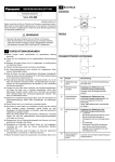
2 PART NAMES INSTRUCTIONS Standard type Compact Photoelectric Sensor CX-400 Series MEUEN-CX400 V2.2 Thank you for purchasing products from Panasonic. Please read this Instruction Manual carefully and thoroughly for the correct and optimum use of this product. Kindly keep this manual in a convenient place for quick reference. WARNING 1 2 3 4 1 2 Basic type • Never use this product as a sensing device for personnel protection. • In case of using sensing devices for personnel protection, use products which meet laws and standards, such as OSHA, ANSI or IEC etc., for personnel protection applicable in each region or country. 1 CAUTIONS This product is designed for industrial use only. Make sure to carry out wiring with the power OFF. Do not use this product in an environment with inflammable or explosive Thru-beam emitter for standard and basic types gas. Incorrect wiring will damage the sensor. Verify that the supply voltage including the ripple is within the rating. If power is supplied from a commercial switching regulator, ensure that 5 the frame ground (F.G.) terminal of the power supply is connected to an actual ground. In case noise generating equipment (switching regulator, inverter motor, etc.) is used in the vicinity of this product, connect the frame ground (F.G.) terminal of the equipment to an actual ground. Do not run the wires together with high-voltage lines or power lines or put them in the same raceway. This can cause malfunction due to induction. Do not use during the initial transient time (50ms) after the power supply is switched on. This sensor is suitable for indoor use only. No. Part Description 1 Stability indicator (green) Lights up under the stable Light or stable Dark condition. 2 Operation indicator (orange) Reflective type, thru-beam receiver: lights up when the sensor output is ON. 3 Sensitivity adjuster Reflective type, thru-beam receiver: sensing range increased when turned clockwise. See “SENSITIVITY ADJUSTMENT” on page 4. 4 Operation mode switch Reflective type, thru-beam receiver: • L: Light-ON Light-ON mode is obtained when the operation mode switch is turned fully clockwise (L). • D: Dark-ON Dark-ON mode is obtained when the operation mode switch is turned fully counterclockwise (D). 5 Power indicator (green) You can extend the cable up to 100m max. with 0.3mm2 or more cable (thru-beam type, both emitter and receiver). However, in order to reduce noise, make the wiring as short as possible. To comply with the requirements for the Korean S-Mark, the power supply line must be 10m or less. Do not apply stress directly to the sensor cable joint by forcibly bending or pulling. Do not use this sensor in places having excessive vapor, dust, etc., or where it may come in direct contact with water or corrosive gas. Take care that the sensor does not come in direct contact with water, oil, grease, or organic solvents such as thinners, etc. Never disassemble or modify the product. 1 Lights up when power in ON. PNP output type 3 CONNECTOR CABLES Color code of cable with connector Connector cables for the M12 pigtailed type 2-core type 4-core type Model no. Cable length CN-22-C2 2m CN-22-C5 5m CN-24-C2 2m CN-24-C5 5m Sensor circuit (Brown / 1) +V Type ZD ZD Tr 100mA max. (Black / 4) Output (note) Load (Blue / 3) 0V Connector cables for the M8 connector type Straight type Elbow type 12 to 24V DC - ±10% D Users' circuit Internal circuit Type + Only the thru-beam receiver incorporates the output. Model no. Cable length CN-24A-C2 2m CN-24A-C5 5m CN-24AL-C2 2m CN-24AL-C5 5m 5 MOUNTING AND ADJUSTING Mount the sensor with a tightening torque of 0.5N·m or less. 12mm M3 screws with washers Two sets of cables are required for the thru-beam type sensor. Sensor mounting bracket (optional) 4 I/O CIRCUIT DIAGRAMS The following symbols are used in this section. Symbol Thru-beam type sensor 1. Set the operation mode switch to the Light-ON mode position (L side). 2. Placing the emitter and the receiver face to face along a straight line. Move the emitter up, down, left and right to determine where light is received with the help of the receiver’s operation indicator (orange). Set the emitter in the middle of this area. 3. Adjust the angle of the emitter by twisting it up, down, left and right. 4. In a similar manner, adjust the angle of the receiver. 5. Check that the stability indicator (green) lights up. 6. Choose the desired operation mode, Light-ON or Dark-ON, with the operation mode switch. Meaning D Reverse supply polarity protection diode ZD Surge absorption zener diode Tr NPN / PNP output transistor Pin assignment M12 pigtailed type M8 connector type 1) +V 2) Not connected 3) 0V 4) Output (see note) 1 2 Terminal name 4 3 2 4 1 3 Object to be sensed Emitter Only the thru-beam receiver incorporates the output. NPN output type Color code of cable with connector Receiver Sensor circuit D Tr (Brown / 1) +V ZD ZD Load (Black / 4) Output (note) + 100mA max. - 12 to 24V DC ±10% (Blue / 3) 0V Internal circuit Users' circuit Only the thru-beam receiver incorporates the output. 2 When sensing glossy objects with CX-493 or transparent objects with CX-48 Installation interval When mounting 2 or more sets of thru-beam type sensors side by side, they must be separated by a certain interval to prevent interference. These measures are not necessary for the retroreflective type with polarizing filters CX-491. L Interval* Interval* 10 - 30° * Interval = 2 x operating point (ℓ) Sensing distance (L) Diagrams for establishing the operating point (ℓ), typical: CX-411 CX-412 (L) 10 5 0 400 (ℓ) 200 0 200 400 30 (L) L (m) 5 40 15 L (m) L (m) 10 1. Make sure the parallel distance (L) between the sensor and the object being sensed is great enough. Otherwise light might be reflected and erroneously detected by the sensor. 2. Install the sensor at an angle of 10 to 30° to the object being sensed. CX-413 20 0 1000 (L) 20 When sensing transparent objects with CX-48 10 For optimum sensing, the distance should be the same between the (ℓ) ℓ (mm) 0 500 ℓ (mm) 1000 transparent object being sensed and the sensor and the transparent object and the reflector. Otherwise, sensing may be unstable. (ℓ) 0 500 4 2 0 2 4 ℓ (m) L = L For example: Installation interval 2xℓ Model no. Sensing distance (L) CX-411 10m Approx. 590mm or more CX-412 15m Approx. 1,580mm or more CX-413 30m Approx. 4.35m or more CX-48 When the sensor detects an irregular plastic receptacle or glass bottle, the received light intensity may differ with the sensing position or direction. Adjust the sensitivity after confirming the stable sensing condition by turning the sensing object, etc. If the object is a transparent cylinder, feed it in a standing, not a lying, position. Retroreflective type sensor Make sure to mount the sensor and the reflector at least 0.1mm apart. OK 1. Set the operation mode switch to the Light-ON mode position (L side). 2. Placing the sensor and the reflector face to face along a straight line. Move the reflector up, down, left and right to determine where light is received the help of the operation indicator (orange). Set the reflector in the middle of this area. 3. Adjust the angle of the reflector by twisting it up, down, left and right. 4. In a similar manner, adjust the angle of the sensor. 5. Check that the stability indicator (green) lights up. 6. Choose the deisred operation mode, Light-ON or Dark-ON, with the operation mode switch. CX-48□ Object to be sensed Reflector Sensor 3 CX-48□ This procedure assumes that “Light-ON” is set for the operation mode. 6 SENSITIVITY ADJUSTMENT To understand sensitivity adjustment, you must first understand the difference between the “light received” and the “dark” condition. Do not confuse the “light received” and “dark” condition with the operation modes “Light-ON” and “Dark-ON”! Diffuse reflective Retroreflective Thru-beam Light received condition Emitter Dark condition Receiver Emitter Sensor Reflector If “Dark-ON” is the operation mode, the output will behave the other way around! Sensor Object to be sensed Object to be sensed Step Receiver Sensitivity adjuster 1 Turn the sensitivity adjuster fully counterclockwise to the minimum sensitivity position, MIN. 2 In the “light received” condition, turn the sensitivity adjuster slowly clockwise to find point A where the sensor output turns Reflector ON.*1 Object to be sensed Sensor 3 Sensor In the “dark” condition, turn the sensitivity adjuster clockwise until the sensor output turns ON.*1 Turn it back slowly to confirm point B, where the sensor output just turns OFF.*1 If the sensor output does not turn ON even when the sensitivity adjuster is turned fully clockwise, point B is the position at MAX. Relationship between output and indicators Light-ON Stability indicator Operation indicator 4 Dark-ON Output ON Sensing condition Stable light Output Operation indicator OFF Unstable dark Optimum position The position exactly between points A and B is the optimum sensing position. Stability indicator OFF Unstable light *1 Remember, this only applies if the operation mode is Light-ON. 7 AUTOMATIC INTERFERENCE PREVENTION FUNCTION ON Stable dark = lit, Description = unlit This function is not available for the thru-beam type sensor. See Use a standard screwdriver and turn the adjuster slowly. Using “INTERFERENCE PREVENTION FILTERS” on page 5. excessive force will damage the adjuster. The automatic interference prevention function allows you to mount up to two sets of sensors next to each other. 2 sensors mounted closely together 4 8 RETROREFLECTIVE TYPE SENSOR WITH POLARIZING FILTERS 10 INTERFERENCE PREVENTION FILTERS Interference prevention filters are only available for the thru-beam As light is polarized by a transparent film or membrane, CX-491 may not detect an object covered or wrapped by transparent film. Such objects include, for example: Can wrapped by clear film Aluminum sheet covered by plastic film Gold or silver (glossy) labels or wrapping paper In such cases, take the following steps. 1. Tilt the sensor with respect to the object to be sensed. 2. Reduce the sensitivity. 3. Increase the distance between the sensor and the object to be sensed. type sensor. By mounting interference prevention filters, two sets of thru-beam type sensors can be mounted close together. However, the sensing range is reduced. The filters can be mounted using the same method as for slit masks. For details, see page 5, section 9, SLIT MASKS. For interference prevention to work, the following conditions must be met. The two sets of sensors must be fitted with different types of interference prevention filters. Filters must be mounted on emitters and receivers. 9 SLIT MASKS The slit mask is only available for the thru-beam type sensor. PF-CX4-H Optional slit masks help the sensor detect small objects. However, the sensing range is reduced. Type Round slit mask Rectangular slit mask Model no. Slit size OS-CX-05 0.5mm OS-CX-1 1mm OS-CX-2 2mm OS-CX-05 x 6 0.5 × 6mm OS-CX-1 x 6 1 × 6mm OS-CX-2 x 6 2 × 6mm PF-CX4-V 3 Model no. Direction of thrubeam axis Color of the bracket PF-CX4-H Horizontal Light brown PF-CX4-V Vertical Silver The model no. is not shown on the interference prevention filters. Take care when mounting them on the sensors. 4 11 DIMENSIONS The basic dimensions of the sensor head are 11.2 x 31.0 x 20.0mm (WxHxD). Slit mask 2 20 11.2 1 2.8 3 How to mount 1. Insert the hook 1 into the bottom groove 2. 2. Press the slit mask until it snaps into the grooves 3 on the top of the main unit. 31 25.4 How to remove 1. Insert a screw driver into the tab 4. 2. Lift and remove carefully. For more detailed information, please refer to the CX-400 Series User’s Manual. For detailed information on the sensing distance and minimum size of the sensing object, please refer to the CX-400 Series User’s Manual. 5 12 SPECIFICATIONS Thru-beam and retroreflective types Thru-beam Item Retroreflective Standard Long sensing range Ultra long sensing range With polarizing filter*1 Long sensing range NPN output CX-411*2 CX-412*2 CX-413*2 CX-491*2 CX-493*2 PNP output CX-411-P*2 CX-412-P*2 CX-413-P*2 CX-491-P*2 CX-493-P*2 10m 15m 30m 3m*3 5m*3 50mm or more opaque, translucent or 50mm or more opaque or translucent specular object*3 object*3 Sensing range 12mm or more opaque object Object to be sensed 0.5mm or less Repeatability (perpendicular to sensing axis) 12 to 24V DC ±10% Ripple P-P 10% or less Supply voltage Current consumption Emitter: 15mA or less Receiver: 10mA or less • • • • Output Emitter: 20mA or less Receiver: 10mA or less Emitter: 25mA or less Receiver: 10mA or less Light-ON or Dark-ON Incorporated Short-circuit protection 1ms or less Response time 2ms or less -25 to +55°C (No dew condensation or icing allowed), Storage: -30 to +70°C 35 to 85% RH, Storage: 35 to 85% RH Ambient humidity Red LED Infrared LED Red LED Enclosure: PBT, Lens: Acrylic, Indicator cover: Acrylic 0.2mm2 3-core (thru-beam type sensor emitter: 2-core) cabtyre cable, 2m long Cable Weight Incorporated IP67 (IEC) Ambient temperature Material 1ms or less — By mounting interference prevention filters*4, two sets of the sensors can be mounted close together. Protection Emitting element 10mA or less NPN or PNP output type NPN or PNP open-collector transistor NPN: Maximum sink current: 100mA; PNP: Maximum source current: 100mA Applied voltage: 30V DC or less (NPN: between output and 0V; PNP: between output and +V) Residual voltage: NPN: 2V or less (at 100mA sink current), 1V or less (at 16mA sink current) PNP: 2V or less (at 100mA source current), 1V or less (at 16mA source current) Output operation Automatic interference prevention function 13mA or less Net Gross Accessory*5 Emitter: approx. 45g ; Receiver: approx. 50g Approx. 50g Approx. 100g Approx. 80g — RF-230 (Reflector): 1 pc. *1The retroreflective type sensor with polarizing filters may not stably detect specular or glossy objects through transparent film since light is polarized by the transparent film. For details, see page 5, section 8, RETROREFLECTIVE TYPE SENSOR WITH POLARIZING FILTERS. *2Model nos. with the suffix -J indicate the M12 pigtailed type. The suffix -Z indicates the M8 connector type. Thru-beam model nos. with the suffix “E” shown on the label affixed to the sensor is the emitter; “D” is the receiver. The retroreflective type sensor model no. with the suffix “-Y” comes without the RF-230 reflector. *3The sensing range and the sensing object for the retroreflective type sensor is specified for the RF-230 reflector. For more detailed information, please refer to the CX-400 Series User’s Manual. After installation, be sure to check operation under actual conditions. *4 For details, see page 5, section 10, INTERFERENCE PREVENTION FILTERS. *5 The RF-230 reflector is included with the product. Other reflectors and reflective tape are available for purchase. For more detailed information, please refer to the CX-400 Series User’s Manual. 6 Diffuse reflective types Narrow view Item NPN output CX-424*1 CX-421*1 CX-422*1 CX-423*1 PNP output CX-424-P*1 CX-421-P*1 CX-422-P*1 CX-423-P*1 100mm*2 300mm*2 800mm*2 70 to 300mm*2 Sensing range Opaque, translucent or transparent object*3 Object to be sensed Opaque, translucent or transparent object*3 *4 15% or less of operation distance*2 Hysteresis 1mm or less Repeatability 0.5mm or less (perpendicular to sensing axis) Supply voltage 12 to 24V DC ±10% Ripple P-P 10% or less Current consumption 13mA or less • • • • Output 15mA or less NPN or PNP output type NPN or PNP open-collector transistor NPN: Maximum sink current: 100mA; PNP: Maximum source current: 100mA Applied voltage: 30V DC or less (NPN: between output and 0V; PNP: between output and +V) Residual voltage: NPN: 2V or less (at 100mA sink current), 1V or less (at 16mA sink current) PNP: 2V or less (at 100mA source current), 1V or less (at 16mA source current) Light-ON or Dark-ON Output operation Incorporated Short-circuit protection Response time 1ms or less Automatic interference prevention function Incorporated IP67 (IEC) Protection Ambient temperature Ambient humidity Emitting element 35 to 85% RH, Storage: 35 to 85% RH Infrared LED Red LED Enclosure: PBT, Lens: Acrylic, Indicator cover: Acrylic Material 0.2mm2 3-core (thru-beam type sensor emitter: 2-core) cabtyre cable, 2m long Cable Weight -25 to +55°C (No dew condensation or icing allowed), Storage: -30 to +70°C Net Approx. 50g Gross Approx. 60g *1Model nos. with the suffix -J indicate the M12 pigtailed type. The suffix -Z indicates the M8 connector type. Thru-beam model nos. with the suffix “E” shown on the label affixed to the sensor is the emitter; “D” is the receiver. The retroreflective type sensor model no. with the suffix “-Y” comes without the RF-230 reflector. *2The sensing range is specified for white non-glossy paper (200 × 200mm) as the object being sensed. *3Sensing may became unstable due to the installation condition or the sensing object. After installation, be sure to check operation with the actual sensing object. *4The minimum size sensing object is 0.5mm copper wire 7 Retroreflective types for sensing transparent objects Short sensing range Standard sensing range Long sensing range NPN output CX-481*1 CX-483*1 CX-482*1 PNP output CX-481-P*1 CX-483-P*1 CX-482-P*1 Sensing range 50 to 500mm*2 50 to 1000mm*2 0.1 to 2m*2 Installation range for the reflector 100 to 500mm*2 100 to 1000mm*2 0.8 to 2m*2 Item 50mm or more for opaque, translucent or transparent object*2 Object to be sensed 0.5mm or less Repeatability (perpendicular to sensing axis) 12 to 24V DC ±10% Ripple P-P 10% or less Supply voltage 10mA or less Current consumption • • • • Output NPN or PNP output type NPN or PNP open-collector transistor NPN: Maximum sink current: 100mA; PNP: Maximum source current: 100mA Applied voltage: 30V DC or less (NPN: between output and 0V; PNP: between output and +V) Residual voltage: NPN: 2V or less (at 100mA sink current), 1V or less (at 16mA sink current) PNP: 2V or less (at 100mA source current), 1V or less (at 16mA source current) Light-ON or Dark-ON Output operation Incorporated Short-circuit protection Response time 1ms or less Automatic interference prevention function Incorporated IP67 (IEC) Protection Ambient temperature -25 to +55°C (No dew condensation or icing allowed), Storage: -30 to +70°C Ambient humidity 35 to 85% RH, Storage: 35 to 85% RH Emitting element Infrared LED Enclosure: PBT, Lens: Polycarbonate, Indicator cover: Polycarbonate Material 0.2mm2 3-core (thru-beam type sensor emitter: 2-core) cabtyre cable, 2m long Weight Cable Net Approx. 50g Gross Approx. 80g RF-230 (Reflector): 1 pc. Accessory*3 *1Model nos. with the suffix -J indicate the M12 pigtailed type. The suffix -Z indicates the M8 connector type. Thru-beam model nos. with the suffix “E” shown on the label affixed to the sensor is the emitter; “D” is the receiver. The retroreflective type sensor model no. with the suffix “-Y” comes without the RF-230 reflector. *2The sensing range and the sensing object for the retroreflective type sensor is specified for the RF-230 reflector. For more detailed information, please refer to the CX-400 Series User’s Manual. After installation, be sure to check operation under actual conditions. *3The RF-230 reflector is included with the product. Other reflectors and reflective tape are available for purchase. For more detailed information, please refer to the CX-400 Series User’s Manual. 8 Basic types Thru-beam Retroreflective*1 Item Light-ON Dark-ON Light-ON Dark-ON Light-ON Dark-ON NPN output CX-411A-C05 CX-411B-C05 CX-412A-C05 CX-412B-C05 CX-491A-C05-Y CX-491B-C05-Y PNP output CX-411A-P-C05 CX-411B-P-C05 CX-412A-P-C05 CX-412B-P-C05 CX-491A-P-C05-Y CX-491B-P-C05-Y 10m Sensing range 15m 12mm or more opaque object Object to be sensed 3m*2 50mm or more opaque, translucent or specular object*2 0.5mm or less Repeatability (perpendicular to sensing axis) 12 to 24V DC ±10% Ripple P-P 10% or less Supply voltage Emitter: 15mA or less Receiver: 10mA or less Current consumption • • • • Output Emitter: 20mA or less Receiver: 10mA or less NPN or PNP output type NPN or PNP open-collector transistor NPN: Maximum sink current: 100mA; PNP: Maximum source current: 100mA Applied voltage: 30V DC or less (NPN: between output and 0V; PNP: between output and +V) Residual voltage: NPN: 2V or less (at 100mA sink current), 1V or less (at 16mA sink current) PNP: 2V or less (at 100mA source current), 1V or less (at 16mA source current) Incorporated Shortcircuit protection 1ms or less Response time Automatic interference prevention function By mounting interference prevention filters, two sets of the sensors can be mounted close together. For details, see page 5, section 10, INTERFERENCE PREVENTION FILTERS. -25 to +55°C (No dew condensation or icing allowed), Storage: -30 to +70°C Ambient temperature 35 to 85% RH, Storage: 35 to 85% RH Ambient humidity Red LED Infrared LED Red LED Enclosure: PBT, Lens: Acrylic, Indicator cover: Acrylic Material 0.2mm2 3-core (thru-beam type sensor emitter: 2-core) cabtyre cable, 2m long Cable Weight Incorporated IP67 (IEC) Protection Emitting element 13mA or less Net Gross Emitter: approx. 20g ; Receiver: approx. 20g Approx. 20g Approx. 50g Approx. 30g *1 The retroreflective type sensor with polarizing filters may not stably detect specular or glossy objects through transparent film since light is polarized by the transparent film. For details, see page 5, section 8, RETROREFLECTIVE TYPE SENSOR WITH POLARIZING FILTERS. *2 The sensing range and the sensing object for the retroreflective type sensor is specified for the RF-230 reflector. For more detailed information, please refer to the CX-400 Series User’s Manual. After installation, be sure to check operation under actual conditions. 9