1
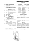
US008054039B2
(12) United States Patent
Bauerle et a].
(54)
US 8,054,039 B2
(10) Patent N0.:
(45) Date of Patent:
(56)
SYSTEM AND METHOD FOR CHARGING A
PLUG-IN ELECTRIC VEHICLE
Nov. 8, 2011
References Cited
U.S. PATENT DOCUMENTS
(75) Inventors: Paul A. Bauerle, Fenton, MI (US);
6,424,122 B2 *
7,560,902 B2 *
Vernon L. NeWhouse, Farmington, MI
2009/0103341 A1 *
(US); Jeffrey T. Wolak, Brighton, MI
Xantrex; PROsine 2.0 Inverter/Charger (User’s Manual); 146 pages;
(73) Assignee: GM Global Technology Operations
WWW.xantrex.c0m.
LLC, Detroit, MI (US)
(*)
* cited by examiner
Subject to any disclaimer, the term of this
patent is extended or adjusted under 35
Primary Examiner * Kenneth J Whittington
(74) Attorney, Agent, or Firm * Lionel D. Anderson;
U.S.C. 154(b) by 445 days.
Reising Ethington RC.
(57)
ABSTRACT
(21) Appl. N0.: 12/340,079
(22)
Filed:
uses this information to charge the plug-in electric Vehicle in
an optimum fashion that reduces charging time yet avoids
damage to components of the charging system. In one
Jun. 24, 2010
Int. Cl.
embodiment, the battery charging system includes an exter
H02] 7/14
H02] 7/04
(52)
(58)
electric Vehicle With poWer from an external poWer source,
such as a standard 110 Volt or 220 Volt AC Wall outlet. The
method senses Various internal and external conditions and
Prior Publication Data
US 2010/0156355 A1
(51)
A battery charging system and method for charging a plug-in
Dec. 19, 2008
(65)
Yagi et al. ................... .. 320/132
Unger ....... ..
320/l4l
Lee et al. .................... .. 363/124
OTHER PUBLICATIONS
(Us)
Notice:
7/2002
7/2009
4/2009
(2006.01)
(2006.01)
nal poWer source, a battery charger With sensors for monitor
ing the external poWer source and the charger, a battery unit
With sensors for monitoring the battery, a battery charging
control module for processing the information, and a user
interface that alloWs user-speci?ed custom charging con
straints. All of these components, With the exception of exter
US. Cl. ...................................... .. 320/109; 320/162
Field of Classi?cation Search ................ .. 320/ 109,
320/145,132,152,157,158,159,162,l63,
320/164; 903/903, 907; 180/651, 65.21,
nal poWer source, may be located on the Vehicle.
180/6529
See application ?le for complete search history.
18 Claims, 2 Drawing Sheets
Sense Condition(s) Pertaining to the
102 /\’ External Power Source, the Battery
Charger and/orthe Battery Unit
i——rgu%——
Evaluate Droop Voltage
Evaluate Current Draw
Evaluate Power Loss
Evaluate Power Draw
Evaluate Minimum
Constraint and
Constraint and
Voltage Constraint and
Generate Third
Generate Fourth
Generate Fifth Charging
Constraint and Generate Constraint and Generate
First Charging Control
Second Charging
Signal
Control Signal
1 10
Charging Control Signal Charging Control Signal
Control Signal
s
s
s
s
120
130
140
150
Evaluate Charger
and Generate Sixth
and Generate Seventh
Evaluate Battery Charge
Constraint(s) and
Generate Eighth
Charging Control Signal
Charging Control Signal
Charging Control Signal
Temperature Constraint
Evaluate Battery
Temperature Constraint
:50
170
v—————l T
t
1%8O
l
Consider the Charging Control Signals Sent by Steps
110-180 and Select the Most Restrictive One
l
Operate the Battery Charger with an Overall Charging
Control Signal
1
F» 200
US. Patent
Nov. 8, 2011
Sheet 1 012
Emo t:BE
US 8,054,039 B2
w cm
9H5%“
b@o5z9m20 6@:5802
w“
vmK
225am (85x8:15
on?
vm_“ED(o:coO
NF
\$c9wt2m0
mE6(B5CEmP
m(Em6£g053mon__2t$an:>g50w
(@vo?5wEr650cmw 6E58:150“
$90
US 8,054,039 B2
1
2
SYSTEM AND METHOD FOR CHARGING A
PLUG-IN ELECTRIC VEHICLE
FIG. 1 is a block diagram of an exemplary system for
charging a vehicle battery, such as those found on a plug-in
electric vehicle; and
TECHNICAL FIELD
FIG. 2 is a ?owchart illustrating an exemplary method for
charging a vehicle battery, and may be used With the system
The present invention generally relates to charging batter
shoWn in FIG. 1.
ies and, more particularly, to a system and method that moni
tors and/or controls charging conditions so that a vehicle
DETAILED DESCRIPTION OF THE PREFERRED
EMBODIMENTS
battery is charged in an optimum fashion.
BACKGROUND
With reference to FIG. 1, there is shoWn an exemplary
battery charging system 10 for a plug-in electric vehicle that
A plug-in electrical vehicle may require electricity in
senses various conditions Within the system and uses the
betWeen vehicle operation in order to charge a rechargeable
sensed conditions to charge the vehicle battery in an optimum
battery pack. In most applications, a battery charger receives
fashion. Battery charging system 10 attempts to charge the
poWer from a poWer source such as a 1 10 VAC outlet, and then
recti?es and/ or transforms the poWer to a form and level that
vehicle battery as quickly as possible yet do so in a manner
that avoids damage to the components of the charging system;
is suitable for charging the battery pack that resides on the
vehicle. The charging conditions Within the system, such as
the temperature of the battery charger, the amount of charge
on the battery, etc., can affect the charging process.
such components can include, for example, the poWer cou
pling that a user selects to connect the vehicle to an external
20
SUMMARY OF THE INVENTION
According to one embodiment, there is provided a method
for charging a plug-in electric vehicle. The method generally
comprises the steps of: (a) sensing at least one condition
25
pertaining to an external poWer source, a battery charger
located on the plug-in electric vehicle, or a battery unit
located on the plug-in electric vehicle; (b) determining a
charging control signal based on the sensed condition; and (c)
charging the battery unit With the battery charger, Wherein the
battery charger is operated according to the charging control
signal and the charging control signal is periodically adjusted
in response to changes in the sensed condition.
According to another embodiment, there is provided a
method for charging a plug-in electric vehicle. The method
generally comprises the steps of: (a) sensing one or more
condition(s) pertaining to an external poWer source, a battery
charger, and a battery unit; (b) evaluating each of the sensed
conditions With a particular battery charging constraint; (c)
revieWing each of the evaluations and identifying the most
poWer source. Although the folloWing description is provided
in the context of a particular battery charging system, it
should be appreciated that this system is merely exemplary
and that other systems could also be used. For example, the
battery charging system and method described beloW can be
used With any type of electric vehicle, including a plug-in
hybrid electric vehicle (PHEV) or a battery electrical vehicle
(BEV), or any other vehicle Where a vehicle battery is charged
With an external poWer source. According to this particular
embodiment, battery charging system 10 includes an external
30
poWer source 12, a battery charger 14, a battery unit 16, a
battery charging control module 18, and a user interface 20.
All of these components, With the exception of external poWer
source 12, may be ?xedly mounted and located on the vehicle.
External poWer source 12 provides battery charging system
35
10 With electrical poWer over a poWer coupling 30, and may
be one of a number of different poWer supply types knoWn in
the art. For example, external poWer source 12 can be a
standard AC poWer outlet that provides 110 v or 220 v of
electricity at 60 HZ, or it can be a portable generator such as
is the one that requests the least amount of current from the
the type that runs on natural gas, propane, gasoline, diesel, or
the like. In one embodiment, external poWer source 12 is a
reneWable poWer source, such as a remote charging station
battery charger; and (d) operating the battery charger so that
poWered by energy from solar panels, Wind turbines, hydro
40
restrictive constraint, Wherein the most-restrictive constraint
electric means, biomass, etc. External poWer source 12 may
it does not violate the most-restrictive constraint.
According to another embodiment, there is provided a
system for charging a plug-in electric vehicle. The system
generally comprises: a battery charger that is located on the
plug-in electric vehicle and has an input coupled to an exter
45
different Ways, including via conductive connections, induc
tive connections, as Well as other connections knoWn in the
art. In an exemplary embodiment, poWer coupling 30 is a
50
specialiZed vehicle poWer coupling (such as those described
in speci?cations SAE J-l772 and J-l773), and includes a ?rst
55
end for plugging into a standard AC Wall outlet and a second
end for plugging into the vehicle. This enables a user to easily
plug and unplug the vehicle from a common AC Wall outlet,
such as those found in most garages. Skilled artisans Will
appreciate that the system and method described herein are
nal poWer source, an output coupled to a battery unit, and one
or more sensor(s) for monitoring external poWer source con
ditions and/or battery charger conditions; a battery unit that is
located on the plug-in electric vehicle and has an input
coupled to the battery charger and one or sensor(s) for moni
toring battery conditions; and a battery charging control mod
ule that is located on the plug-in electric vehicle and is
coupled to both the battery charger and the battery unit. The
battery charging control module receives readings from the
battery charger sensor(s) and the battery sensor(s) and uses
those readings to control the output poWer that the battery
charger provides the battery unit.
be connected to battery charger 14 in one of a variety of
not limited to any particular external poWer source, as a
number of different poWer source types could be used.
Battery charger 14 is connected to both external poWer
60
source 12 and battery unit 16, and uses the poWer from the
external poWer source to charge the battery unit according to
charging control signals from battery charging control mod
ule 18. According to an exemplary embodiment, battery
charger 14 is a programmable charger that is mounted in the
BRIEF DESCRIPTION OF THE DRAWINGS
Preferred exemplary embodiments of the invention Will
hereinafter be described in conjunction With the appended
draWings, Wherein like designations denote like elements,
and Wherein:
vehicle and includes a transformer 32, a recti?er 34, a sWitch
65
ing poWer supply 36, a ?lter netWork 38, cooling unit 40, one
or more sensors 42, a control unit 44, and any other suitable
components knoWn in the art.
US 8,054,039 B2
4
3
Battery unit 16 provides the plug-in electric vehicle With
electrical poWer and, depending on the particular embodi
Depending on the particular arrangement, transformer 32
steps-up and/or steps-doWn the input voltage from external
ment, may be the primary vehicle poWer source or may be
used in conjunction With another poWer source for poWer
power source 12 to a different and, in some cases, program
mable output voltage. Recti?er 34 recti?es the AC signal into
a DC signal and includes a half-Wave, full-Wave or other type
supplementation purposes, to cite tWo examples. Many dif
of knoWn rectifying arrangement. SWitching poWer supply 36
ferent battery types and arrangements may be used, including
takes the recti?ed signal and, according to one embodiment,
the exemplary one schematically shoWn here Which includes
rapidly sWitches a poWer transistor or other sWitch betWeen
a battery pack 60, one or more battery sensors 62, and a
saturation (‘on’) and cutoff (‘off’) according to a variable
duty cycle Whose average corresponds to the desired output
voltage. In this Way, sWitching poWer supply 36 is able to
control unit 64. Battery pack 60 may include a collection of
identical or individual battery cells connected in series, par
control the amount of current, and hence poWer, that is pro
voltage, amperage, capacity, poWer density, and/or other per
formance characteristics. Generally, it is desirable to provide
high poWer and energy densities, Which has led to the devel
opment and use of many types of batteries including chemi
cal, non chemical, and others. Some examples of chemical
batteries that could be used include lead acid, advanced lead
allel, or a combination of both in order to deliver a desired
vided by battery charger 14 to battery unit 16. Filter network
38, Which is optional, may include any combination of elec
trical components that can be used to ?lter, process, or con
dition the output signal before providing it to battery unit 16.
Cooling unit 40, also an optional component, may use any
combination of fans, Water jackets, heat sinks, or any other
suitable cooling means to reduce the temperature of battery
acid, nickel metal hydride (NiMH), nickel cadmium (NiCd),
high voltage output connected to battery unit 16 (connection
lithium ion, Zinc bromide, lithium polymer, sodium nickel
chloride (NaNiCl), Zinc air, vanadium redox, and others.
Other chemical battery types include aluminum air, iron air,
lithium iron sul?de, nickel iron, nickel Zinc, silver Zinc,
50) and a loWer voltage output (not shoWn) connected to a 12
V battery, for example.
sodium sulfur, Zinc chlorine, Zinc manganese, and more.
According to one embodiment, battery unit 16 includes a
charger 14 during charging. Although not shoWn here, battery
20
charger 14 could have multiple poWer outputs including a
Battery charger sensors 42 may include any combination of
25
hardWare and/or softWare components capable of monitoring
battery charger conditions such as charger temperature,
large number of lithium ion cells, each of Which exhibits
betWeen 2 v-4 v When charged and is connected in a series
and/or parallel con?guration With its adjacent cells. Skilled
charger input voltage (typically anAC signal), charger output
artisans Will appreciate that the system and method described
voltage (typically a DC signal), charger current, etc. Depend
herein are not limited to any one particular type of battery or
ing on the particular embodiment, these sensors may be inte
30
Battery sensors 62 may include any combination of hard
Ware and/or softWare components capable of monitoring bat
vided according to some other knoWn arrangement. The
charger temperature sensor may sense the temperature of one
or more components Within battery charger 14, including the
temperature of the least e?icient component; that is, the com
ponent of the battery charger that exhibits the most heat.
Battery charger sensors 42 may be coupled directly to control
35
40
outside of battery charger 14, like battery charging control
module 18.
Control unit 44 may include any variety of electronic pro
region of the battery unit, as the average or collective tem
perature of the entire battery unit, or according to some other
45
temperature determining method knoWn in the art. Measuring
battery temperature on an individual cell basis may be ben
e?cial if, for example, the middle cells exhibit different tem
peratures than the edge or boundary cells of battery pack 60.
appropriate sensor message, and send the sensor message to
battery charging control module 18 over a connection 52,
ment. The battery temperature sensors may monitor and
determine the battery temperature on a cell-by-cell basis, as
the average or collective temperature of a block of cells or
cessing devices, memory devices, input/ output (I/O) devices,
and other knoWn components, and may perform various con
trol and/or communication related functions. For example,
control unit 44 could receive sensor signals from the various
battery charger sensors 42, package the sensor signals into an
tery conditions such as battery temperature, battery voltage,
battery current, battery state of charge (SOC), battery state of
health (SOH), etc. These sensors may be integrated Within
battery unit 16 (e.g., an intelligent or smart battery), they may
be external sensors located outside of the battery unit, or they
may be provided according to some other knoWn arrange
unit 44, or they could be coupled to an any number of other
devices, components, modules, etc., including some located
battery arrangement, as a number of different battery types
could be employed.
grated Within battery charger 14, they may be external sensors
located outside of the battery charger, or they may be pro
50
The same principal of determining battery temperature on a
cell-by-cell, collective or other basis also applies to battery
such as a CAN bus, a system management bus (SMBus), a
voltage, battery current, battery SOC, battery SOH, etc. Out
proprietary communication link, or any other communication
put from battery sensors 62 may be provided to control unit
64, battery charging control module 18, or some other appro
means knoWn to those skilled in the art. In another capacity,
control unit 44 may receive charging control signals or other
instructions from battery charging control module 18 or some
priate device.
55
Control unit 64 may include any variety of electronic pro
other device, interpret the instructions, and execute the
cessing devices, memory devices, input/ output (I/ O) devices,
instructions by correspondingly controlling devices Within
battery charger 14. For instance, if battery charging control
and other knoWn components, and may perform various con
trol and/or communication related functions. For example,
control unit 64 could receive sensor signals from the various
battery sensors 62, package the sensor signals into an appro
module 18 sends a charging control signal to battery charger
14, then control unit 44 can use the charging control signal to
60
manipulate the pulse Width modulated (PWM) duty-cycle of
priate sensor message, and send the sensor message to battery
sWitching poWer supply 36. This, in turn, causes sWitching
charging control module 18 over a connection 54, such as a
poWer supply 36 to alter the amount of current, and ultimately
the amount of poWer, that is provided by battery charger 14 to
battery unit 16. These are, of course, only some of the possible
CAN bus, a system management bus (SMBus), a proprietary
communication link, or any other communication means
arrangements and functions of control unit 44, as others are
knoWn to those skilled in the art. It is possible for control unit
64 to gather battery sensor readings and store them in local
certainly possible.
memory so that a comprehensive sensor message can be
65
US 8,054,039 B2
5
6
provided to battery charger control module 18 at a later time,
or the sensor readings can be forWarded to module 18 or some
enter a current limitifor example, 10 amps. This user-speci
?ed parameter could then limit the AC current draW from
other destination as soon as they arrive at control unit 64, to
external poWer source 12 to no more than 10 amps, even if
cite a feW possibilities. In another capacity, control unit 64
can store pertinent battery characteristics and background
optimum charging conditions permitted otherWise. In another
example Where battery charging system 10 is to be poWered
by a remote charging station of limited poWerifor example,
information pertaining to the battery’s cell chemistry, cell
capacity, upper and loWer battery voltage limits, battery cur
a solar-poWered remote charging stationithe user could
enter a poWer limit of 400 Watts, for example. User-de?ned
limits on current, voltage, poWer, or any other charging
parameter could be entered via user interface 20. User inter
face 20 may be part of battery charging control module 18 or
it can be an independent interface. Depending on the particu
lar embodiment, user interface 20 may be mounted on the
dashboard (e.g., With a driver information center (DIC)) or
elseWhere, or it simply may include an electronic connection
or port for connecting With a laptop or other computing
device. This Way, a user can provide user-speci?ed param
rent limits, battery temperature limits, temperature pro?les,
battery impedance, number or history of charge/discharge
events, etc.
Battery charging control module 18 monitors one or more
conditions pertaining to external poWer supply 12, battery
charger 14, and/or battery unit 16, and uses the sensed con
ditions to control the charging process in an optimum manner.
Depending on the particular embodiment, battery charging
control module 18 may be a stand-alone vehicle electronic
module, it may incorporated or included Within another
vehicle electronic module (such as a poWer train control mod
ule), or it may be part of a larger network or system (such as
a battery management system (BMS), a vehicle energy man
eters and charging commands to battery charging system 10
20
During an exemplary charging operation, external poWer
source 12 provides a high voltage AC signal (e.g., 110 volts,
220 volts, etc.) to battery charger 14. Recti?er 34, Which may
agement system, etc.), to name a feW possibilities. Battery
charging control module 18 may also be or part of or interact
With a system that determines a desired operating mode (e.g.,
accelerating, braking, idling, stopping, etc.) and may imple
ment electrical poWer management actions accordingly. Bat
tery charging control module 18 may perform a number of
include a full-Wave recti?er or bridge, recti?es the high volt
25
age AC signal into a high voltage recti?ed signal. The high
voltage recti?ed signal is then provided to transformer 32,
Which steps-up the input voltage to provide a constant high
voltage DC signal. The high voltage DC signal is ?ltered and
connected to battery unit 16 via sWitching poWer supply 36,
30
Which may use pulse-Width modulation (PWM) or some
functions pertaining to the battery charging system 10; these
could include, for example, cell protection, charge control,
demand management, SOC and SOH determination, cell bal
ancing, history logging, communications, etc.
Battery charging control module 18 may include any vari
other technique to vary the poWer provided to the battery unit.
For example, assume that a 110 volt AC input is recti?ed and
stepped-up to a relatively constant 500 volt DC output. Bat
tery charging control module 18 can control the output poWer
ety of electronic processing devices, memory devices, input/
output (I/O) devices, and other knoWn components, and may
perform various control and/or communication related func
tions. The battery charging control module can be electroni
35
cally connected to other vehicle devices and modules via a
suitable vehicle communications network, and can interact
With them When required. In an exemplary embodiment, bat
tery charging control module 18 includes an electronic pro
cessing device that executes instructions for softWare, ?rm
40
Ware, programs, algorithms, scripts, etc. that are stored in
memory devices of module 18 and govern the battery charg
ing processes and methods described herein. Battery charging
supplied from battery charger 14 to battery unit 16 by pro
viding a charging control signal to manipulate the amount of
current provided at this elevated and constant voltage. One
Way to manipulate or control the current is to adjust the duty
cycle of a PWM signal sent to sWitching poWer supply 36,
although other techniques could certainly be used. It should
be appreciated that battery charging system 10 is not limited
to the foregoing example Where the voltage is maintained
relatively constant and the current is adjusted; it is also pos
sible to control the voltage or some other aspect of the output
control module 18 could also store or maintain look up tables
(e.g., performance response curves representing cell dis
charge/ charge performance as a function of temperature,
etc.), various sensor readings (e.g., sensor readings pertaining
via a Wired or Wireless connection.
45
poWer provided by battery charger 14.
Turning to FIG. 2, there is shoWn an exemplary method 100
for charging a plug-in electric vehicle, such as a PHEV, Where
the method may use various readings, conditions, informa
to battery charger conditions, battery conditions, etc.), and
predetermined values used by one or more algorithms (e.g.,
possible functions and capabilities of battery charging control
tion, comparisons, calculations, etc. to charge the vehicle in
an optimum fashion. An optimum charging process, Which
may involve charging battery unit 16 in the shortest time
possible, can be affected by external conditions (e.g., the
module 18, as other embodiments could also be used.
poWer available from external poWer source 12) or internal
predetermined condition values, condition calibration values,
50
etc.), for example. These are, of course, only some of the
User interface 20 is an optional component that, according
to the embodiment shoWn here, conveys battery charging
55
conditions (e. g., the poWer generation capabilities of battery
charger 14, the poWer acceptance capabilities of battery unit
information to a user, receives charging limitations and user
16, etc.). Thus, exemplary method 100 can monitor these and
speci?ed conditions from a user, and facilitates any other
other factors in a closed-loop fashion in order to quickly
communication betWeen battery charging system 10 and a
charge battery unit 16, avoid damaging parts of battery charg
user. For example, user interface 20 may display the current
charge status of battery unit 16 to the driver in a numerical,
ing system 10, and avoid overloading the circuit to Which
60
graphical, or other type of electronic presentation. In another
external poWer source 12 is connected. As conditions pertain
example, user interface 20 also permits a user to enter user
ing to the external poWer source, the battery charger, and/or
the battery unit change, so too can the charging control signal
speci?ed condition calibration values or other input into bat
Which is periodically adjusted according to one or more
closed-loop techniques to optimally charge the plug-in elec
tery charging system 10. To illustrate, if a user intends on
supplying battery charging system 10 With electricity from a
particular AC Wall outlet but knoWs that a number of other
loads already exist on the same circuit, then the user could
65
tric vehicle. ‘Periodically’ does not necessarily require that
the charging control signal be modi?ed according to a speci?c
time interval, but rather includes the broad concept of con
US 8,054,039 B2
7
8
tinuously monitoring and making changes to the charging
external poWer source voltage are generally the same because
there are no poWer losses in poWer coupling 30. The droop
voltage may then be calculated as the difference betWeen the
control signal in response to sensed conditions.
Beginning With step 102, the method senses one or more
conditions pertaining to external poWer source 12, battery
charger 14, battery unit 16, and/ or any other external or inter
unloaded and loaded voltage readings. Once the droop volt
nal conditions pertaining to the charging process. In an exem
proportional-integral-derivative (PID) or other closed-loop
plary embodiment, battery charger sensors 42 sense charger
techniques to determine a ?rst charging control signal. Such
a process is illustrated in the folloWing example, hoWever,
age is determined, step 110 may use this constraint With
temperature, charger input voltage, charger output voltage,
other non-PID techniques could be used as Well.
Assume that step 110 calculates a droop voltage of 2.5 volts
and a predetermined droop voltage or setpoint of up to 4.0
and/or charger current; and battery unit sensors 62 sense
battery temperature, battery voltage, battery current, battery
SOC, and/or battery SOH. Of course, other combinations of
sensor readings and conditions could also be gathered. Each
sensor reading could be representative of a single sampled
reading, of a number of readings averaged or ?ltered over
time, or of readings processed according to some other signal
processing or ?ltering technique knoWn in the art. Once the
sensor readings are obtained, they can be provided to battery
charging control module 18 for further processing. It is pos
sible for these sensor readings to be provided to battery charg
ing control module 18 in response to a query or request from
the module, or they can be provided on a periodic basis
volts is alloWed by the system (this predetermined limit could
be stored in the memory of battery charging control module
18, for example). The 2.5 volts is a calculated estimate
because some portion of the measured droop voltage could be
caused by factors other than battery charging system 10, such
as other devices draWing current from the circuit When the
unloaded voltage is determined, etc. An error is determined
by subtracting the calculated droop voltage from the setpoint;
20
Without being requested, for example. It should be appreci
ated that some of the battery charger conditions may actually
pertain to certain aspects of external poWer source 12, even
though they are sensed and provided by battery charger sen
sors 42. For instance, the charger input voltage is representa
25
obtain a product that can be used to generate the ?rst charging
control signal, Which is representative of the constraints on
the droop voltage. Persons skilled in the art Will knoW of a
number of different Ways and techniques that could be used
With the preceding steps, including the folloWing: using abso
lute setpoints (e. g., 4.0 volts); using percentage setpoints
(e.g., a voltage drop of 10%); using user-speci?ed setpoints
tive of not only the voltage seen at the input of the charger but
also the unloaded voltage at external poWer source 12, and the
charger input current is representative of both the current
entering battery charger 14 and the line current provided by
in this case, 4.0 v—2.5 v:l .5 v. The 1.5 v error is then multi
plied by a droop voltage calibration value or gain in order to
30
that can be modi?ed; using empirically tested gains that have
predictable outcomes on the condition being evaluated (e. g.,
the external poWer source.
for each amp of additional battery charger current, the droop
Next, the method compares or evaluates each of the sensed
conditions With a speci?c predetermined limit and uses the
voltage is expected to increase by 0.5 volts); using gains that
output of this comparison to generate a corresponding charg
ing control signal that is representative of that particular con
straint. The various charging control signals are evaluated
are derived from optimum charging curves or other functions,
35
as opposed to being a single gain value (e.g., a gain that is
determined according to a complex relationship that relates
droop voltage to battery charger output current); using gains
together, and the most restrictive constraint is used to gener
that are selected from a ?nite number of states (e.g., if the
ate the actual charging control signal that is sent from charg
ing control module 18 to battery charger 14 and controls the
charging process. This Way, battery charger 14 can be pushed
droop voltage is less than a certain amount then the charging
control signal requests a ?rst amount of battery charger cur
rent, and if the droop voltage is greater than a certain amount
then the charging control signal requests a second amount of
40
to charge battery unit 16 as quickly or aggressively as pos
sible, but is still limited by the most restrictive of the various
battery charger current); and alloWing for negative error val
charging conditions. According to an exemplary embodi
ment, each of the charging control signals generated in steps
110-180 controls the amount of current provided by battery
ues to address instances of over-shoot (e.g., if the sensed
45
droop voltage is 4.5 volts, this produces an error value of 4.0
v—4.5 v:—0.5 v), to cite a feW examples. Once the ?rst charg
charger 14 to battery unit 16 so that step 200 can make an
ing control signal is determined in step 110, it is provided to
apples-to-apples comparison and select the most restrictive
one (e. g, the one With the loWest duty cycle). Thus, the charg
ing control signal selected in step 200 is generally represen
ing device for subsequent processing in step 200, as Will be
tative of the most restrictive of the various conditions and
constraints that Were evaluated. Steps 110-180 may be per
formed concurrently, sequentially, or according to any other
suitable monitoring arrangement, as the present method is not
limited to the exemplary sequence described here.
Step 110 evaluates a droop voltage constraint and gener
ates a corresponding ?rst charging control signal. The droop
a state-machine, neural netWork or any other logical process
explained.
50
55
It should be appreciated that the closed-loop system
described above is only one possible technique and method
that could be used to evaluate a droop voltage constraint and
to generate a corresponding ?rst charging control signal, as
other embodimentsiincluding both closed-loop and non
closed-loop4could also be used. Because similar processes
and techniques can also be used to evaluate the various con
voltage inbattery charging system 10 generally represents the
straints in steps 120-180, duplicate discussions of closed
voltage difference of external poWer source 12 betWeen an
unloaded state (i.e., When little or no current is being draWn by
loop control processes for each of these constraints have been
omitted. It should be appreciated that the preceding closed
system 10) and a loaded state. According to an exemplary
60
embodiment, step 110 measures the charger input voltage
When no current is ?oWing through poWer coupling 30 (the
unloaded voltage) and measures the charger input voltage
When some current is ?oWing therethrough (the loaded volt
age), at Which time both the charger input voltage and the
charger input current are measured. Skilled artisans Will
appreciate that the unloaded charger input voltage and the
loop control discussion may pertain to one or more of the
folloWing steps as Well.
Step 120 evaluates a current draW constraint and generates
a corresponding second charging control signal. The current
draW constraint relates to the maximum amount of current
65
that battery charging system 10 is alloWed to draW from
external poWer source 12, and it can be a predetermined limit
or it can be user-speci?ed. There are a number of reasons Why
US 8,054,039 B2
10
the minimum voltage level of 106 volts, then the ?fth charg
ing control signal can be modi?ed to request less output
poWer from battery charger 14. If the unloaded voltage actu
ally falls beneath the minimum voltage level of 106 volts, then
the ?fth charging control signal may request that battery
charger 14 supply no poWer to battery unit 16 until this loW
method 100 may Want to monitor and limit the current draW
by battery charging system 10, one of Which is to avoid
tripping a circuit breaker of external poWer source 12. Con
sider the example Where a maximum current draW limit of 15
amps (setpoint) is alloWed, and the battery charger input
current is measured at 10 amps. According to one embodi
ment, step 120 calculates an error of 5 amps, multiplies the 5
amp error by a calibration or gain value, and uses the product
to derive a second charging control signal. The larger the error
in current draW (i.e., the further aWay the actual current draW
voltage or broWnout condition abates.
Step 160 evaluates a battery charger temperature constraint
and generates a corresponding sixth charging control signal.
The amount of poWer that can be delivered by battery charger
14 to battery unit 16 may be affected or limited by the tem
is from its upper limit), the more aggressively the second
charging control signal may attempt to increase the output
poWer of battery charger 14.
perature of the charger. For example, if the internal tempera
ture of battery charger 14 exceeds an upper threshold, various
components of the battery charger can be damaged or
Step 130 evaluates a poWer loss constraint and generates a
corresponding third charging control signal. The poWer loss
is alloWed in poWer coupling 30. This evaluation may be
destroyed (hence, the use of cooling unit 40). Moreover, the
actual charging ef?ciency or the ability of the battery charger
helpful in cases Where a poWer outlet is corroded, a poWer
to generate a constant high voltage signal and control the
constraint relates to the maximum amount of poWer loss that
amount of output poWer sent to the battery unit may be some
coupling is deteriorated, or in cases Where a user selects an
inappropriate electrical connection such as a thin Wire exten
20
sion cord, for example. Generally speaking, the poWer loss in
poWer coupling 30 can be estimated by multiplying the droop
sensors 42 to a predetermined limit or setpoint to obtain an
voltage by the battery charger input current. Consider the
example above Where the droop voltage is 2.5 volts, the
battery charger input current or line current is 10 amps, and
the maximum amount of alloWed poWer loss or setpoint is 40
Watts. The calculated poWer loss is 25 Watts, hoWever, not all
of the droop voltage and hence poWer loss may be attributable
to losses in poWer coupling 30, as explained above. For pur
poses of conservatively estimating the poWer loss in poWer
coupling 30, step 130 may assume that all of the calculated
poWer loss is due to losses in the poWer coupling. The calcu
error value, and multiplies the error value by a calibration or
25
a single gain value) that relates battery charger ef?ciency to
battery charger temperature.
Step 170 evaluates a battery temperature constraint and
30
35
charging control signal. Once the third charging control sig
nal is determined it can be provided to step 200, as mentioned
above.
Step 140 evaluates a poWer draW constraint and generates
a corresponding fourth charging control signal. The poWer
40
draW constraint relates to the maximum amount of poWer that
is alloWed to be draWn from external poWer source 12, and
may be calculated as the unloaded charger input voltage mul
tiplied by the charger input current. As With the current draW
limit, the poWer draW limit or setpoint may be speci?ed and
changed by a user via user interface 20. Consider the example
Where a poWer draW of 1,100 Watts is measured (1 10 volts* 10
amps), a default maximum poWer draW of 1,650 Watts is
alloWed, and the user provides a user-speci?ed maximum
poWer draW limit of 1,500 Watts. According to one embodi
ment, step 140 ?rst selects the more restrictive of the tWo
maximum poWer draW limitsiin this case the user-speci?ed
1,500 Wattsicompares the measured amount of 1,100 Watts
to the 1,500 Watt limit to obtain an error of 400 Watts, and
multiplies the error by a calibration or gain value in order to
derive or otherWise determine the fourth charging control
gain value in order to determine the sixth charging control
signal. It is possible for step 160, or any of the other steps for
that matter, to use a calibration or gain function (as opposed to
lated poWer loss of 25 Watts can be subtracted from the
setpoint of 40 Watts to obtain an error value of 15 Watts, Which
in turn can be multiplied by a gain factor to produce the third
What temperature dependent. In an exemplary embodiment,
step 160 compares the charger temperature readings from
generates a corresponding seventh charging control signal.
The temperature of battery unit 1 6, Whether it be the tempera
ture of the overall battery pack 60, a region or portion of the
battery pack, the temperature of an individual cell, etc., can
affect the ability or ef?ciency of the battery unit to accept a
charge. In one embodiment, step 170 compares a sensed
battery temperature With one or more predetermined battery
temperature limits or setpoints (there could be loWer and/or
upper temperature limits). An error value is obtained and
multiplied by a compensation or gain value, as explained
above. The product of this calculation can be used to generate
the seventh charging control signal. In the event that both
loWer and upper temperature constraints are considered, step
170 may generate tWo separate charging control signals; one
for the upper limit and one for the loWer limit. Depending on
45
the particular application, each of these charging control sig
nals may request a reduction in battery charger output poWer
as the battery temperature approaches either the upper or the
loWer limit.
50
Step 180 evaluates battery charge constraints and generates
a corresponding eighth charging control signal. The battery
charge constraints considered and evaluated in this step could
include any conditions that pertain to the charge or charging
status of the battery. For example, step 180 could compare a
battery voltage reading, a battery current reading, a battery
55
SOC reading, a battery SOH reading, or some other battery
perfor'mance reading to a predetermined limit or setpoint in
signal.
order to obtain an error value. The error value could then
Step 150 evaluates a minimum voltage constraint and gen
erates a corresponding ?fth charging control signal. It is pos
sible for external poWer source 12 to experience voltage ?uc
multiplied by a compensation or gain value, as explained
above, to derive the eighth charging control signal. It should
60
be appreciated that this step is not limited to producing a
single charging control signal, as separate signals could be
tuations, including so-called broWnout situations Where the
supply voltage drops beloW an ordinary and normal level.
generated for each of the constraints listed above. For
instance, a charging control signal could be generated for a
Consider the example Where an unloaded voltage level of 1 10
battery voltage constraint, a separate charging control signal
volts is sensed and a minimum voltage level of 106 v is stored
multiplied by a calibration or gain value to determine the ?fth
could be generated for a battery current constraint, and
another charging control signal could be generated for a SOC
charging control signal. If the unloaded voltage approaches
constraint. One or more of these charging control signals,
as a default setpoint. The calculated error is 4 volts and can be
65
US 8,054,039 B2
11
12
such as the ones relating to the SOC and the SOH constraints,
could include cutoffs if the SOC or other condition exceeds a
certain amount.
It should be appreciated that any combination of con
could reduce the cost of the system, as a neW battery charger
Would not need to be individually developed for each vehicle;
rather, engineers could simply alter the various setpoint val
ues, calibration or gain values, other softWare settings, etc.
In addition to the different steps and techniques described
above, one or more of the folloWing optional features could
also be employed by exemplary method 100. In addition to
the constraints of steps 110-180, method 100 could Watch for
a variety of different fault conditions, Where if any one of
these fault conditions or ‘hard limits’ is detected, the method
stops the charging process and noti?es the user, vehicle, etc.
of the situation. One Way to perform such noti?cation is
through the use of a diagnostic trouble code (DTC), Which
straints and charging control signals could be evaluated and
generated, and that the present method is not limited to the
exemplary combination provided above. Moreover, any of the
constraints and charging control signals discussed above
could utiliZe user-speci?ed limitations or setpoints. For
example, a user may establish or adjust the maximum current
draW alloWed in step 120 or the maximum poWer draW
alloWed in step 140. If a user knoWs that a particularAC outlet
in the garage is part of a Widely used circuit, then they may
Want to loWer the current draW limit from 15 amps to 10 amps
could be used With a fault condition or during the normal
to avoid tripping the corresponding circuit breaker. The user
could provide this information via user interface 20. Con
versely, if an AC outlet in the garage has been speci?cally
charging process. For example, if step 130 detects a high
poWer loss that is likely attributable to a bad poWer coupling,
then a corresponding DTC could be generated that provides
information on the problem. It is also possible for method 100
to periodically sample the unloaded voltage of external poWer
Wired on its oWn dedicated 20 amp circuit, then the user could
increase the maximum alloWed poWer draW to 2,200 Watts,
for example. Such an increase could result in a quicker
charge, assuming that it does not run afoul of any of the other
constraints discussed herein.
20
Once the various constraints have been evaluated and cor
utes, and Wait for 100 ms or so to take a neW unloaded voltage
responding charging control signals have been generated,
step 200 considers the signals and produces an overall charg
ing control signal to send to battery charger 14 for controlling
the charging process. According to an exemplary embodi
ment, step 200 examines the various signals sent in steps
110-180, selects the charging control signal that represents
the most restrictive constraint (e. g., the signal With the small
est duty cycle or the signal that otherWise requests the least
amount of output poWer by the battery charger), and sends the
overall or selected charging control signal from battery charg
ing control module 18 to battery charger 14. Skilled artisans
Will knoW of a variety of tools and techniques that could be
source 12 and to update any calculations, such as droop volt
age, With the neW readings. For example, method 100 could
stop the charging process every so often, say every 10 min
reading. It is also possible for one or more of the steps in
25
method 100 to employ a hysteresis factor When determining
their requested charging control signals. If battery charger 14
is also used to supply other poWer sources, such as loW volt
age batteries, etc., then method 100 could take that additional
poWer draW into account When determining the optimum
30
poWer output of battery charger 14.
It should be appreciated that a variety of different battery
charger types, schemes and charging techniques could be
used With method 100 and/ or system 10, including: constant
voltage charging, semi-constant voltage charging, constant
35
current charging, semi-constant current charging, constant
current/constant voltage charging, taper current charging,
pulsed charging, burp charging (i.e., re?ex or negative pulse
used to perform step 200, including the use of a state-ma
chine, neural netWork or any other logical processing device
or netWork. It is not necessary that all of the charging control
charging), IUI charging, trickle charging, ?oat charging, ran
signals from steps 110-180, Which are actually charge request
dom charging, sloW charging (e.g., 14-16 hours), quick charg
signals, be sent in the form a PWM current-controlling signal.
Rather, they could be in various forms and could be translated
or interpreted at step 200, they could be non-PWM current
controlling signals, or they could control other aspects of the
battery charger poWer output other than current, to provide a
40
feW possibilities.
In step 202, battery charger 14 is operated according to the
45
ing (3-6 hours), fast charging (1 hour or less), timer controlled
charging, intelligent charging, sWitcher charger types (e.g.,
sWitch mode regulator), linear charger types (e. g., series regu
lator), shunt, buck and inductive charger types, etc. In addi
tion, battery charger 14 may be designed for speci?c cell
chemistries or for universal cell applicability, and it may be
self-programmable or user-programmable, to name a feW
possibilities.
overall charging control signal that Was previously sent. As
already mentioned, the overall battery charging control signal
It is to be understood that the foregoing description is not a
could be used to manipulate the amount of current provided
by battery charger 14 to battery unit 16 by means of PWM or
some other control technique. This Way, method 100 may
charge the plug-in vehicle in an aggressive manner that aims
to reduce the charging time, yet do so in a Way that balances
de?nition of the invention, but is a description of one or more
a number of parallel constraints driven by one or more inter
nal and/ or external conditions. Method 100 could then be
repeated until step 180 sends a state of charge (SOC) control
signal indicating that battery unit 1 6 has reached a charging or
other limit.
The charging method described herein may be particularly
useful in less than ideal charging conditions; that is, When the
50
preferred exemplary embodiments of the invention. The
invention is not limited to the particular embodiment(s) dis
closed herein, but rather is de?ned solely by the claims beloW.
Furthermore, the statements contained in the foregoing
description relate to particular embodiments and are not to be
55
construed as limitations on the scope of the invention or on the
de?nition of terms used in the claims, except Where a term or
phrase is expressly de?ned above. Various other embodi
60
poWer provided by external poWer source 12 is unstable or
ments and various changes and modi?cations to the disclosed
embodiment(s) Will become apparent to those skilled in the
art. All such other embodiments, changes, and modi?cations
are intended to come Within the scope of the appended claims.
inconsistent, When poWer coupling 30 is experiencing some
As used in this speci?cation and claims, the terms “for
type of operational issues, or When some other conditioni
either internal or external to the systemipresents challenges
example,” “for instance,” “such as,” and “like,” and the verbs
“comprising,” “having,” “including,” and their other verb
to the charging process. Moreover, battery charging system
10 may be used With a variety of different vehicles and is not
limited to any one vehicle make and model. Such ?exibility
65
forms, When used in conjunction With a listing of one or more
components or other items, are each to be construed as open
ended, meaning that that the listing is not to be considered as
US 8,054,039 B2
14
13
12. The method of claim 1, further comprising the step of:
excluding other, additional components or items. Other terms
are to be construed using their broadest reasonable meaning
evaluating one or more fault conditions and if a fault con
unless they are used in a context that requires a different
dition is detected, then stopping the charging process.
13. The method of claim 1, further comprising the step of:
interpretation.
The invention claimed is:
1. A method for charging a plug-in electric vehicle, com
generating a diagnostic trouble code (DTC) that provides
information regarding the sensed condition.
14. The method of claim 1, further comprising the steps of:
prising the steps of:
(a) sensing at least one condition pertaining to an external
poWer source, a battery charger located on the plug-in
electric vehicle, or a battery unit located on the plug-in
electric vehicle, Wherein the sensed condition is at least
partially based on an unloaded voltage of the external
poWer source Which is measured When the external
putting the external poWer source in an unloaded state
Where there is little or no current being draWn from the
external poWer source by the battery charger; and
periodically sampling the unloaded voltage of the external
poWer source and using the unloaded voltage of the
poWer source is in an unloaded state and there is little or
no current being draWn from the external poWer source
external poWer source to make at least one calculation
by the battery charger located on the plug-in electric
the external poWer source, poWer loss in a poWer cou
vehicle;
pling, poWer draW from the external poWer source, or
minimum voltage of the external poWer source.
selected from the group consisting of: droop voltage in
(b) determining a charging control signal based on the
sensed condition that is at least partially based on an
unloaded voltage of the external poWer source; and
20
(c) charging the battery unit With the battery charger,
Wherein the battery charger is operated according to the
charging control signal and the charging control signal is
plurality of sensed conditions, and determining the charging
periodically adjusted in response to changes in the
sensed condition.
2. The method of claim 1, Wherein step (a) further com
prises sensing at least one condition that pertains to the exter
nal poWer source and is selected from the group consisting of:
droop voltage in the external poWer source, current draW from
the external poWer source, poWer loss in a poWer coupling,
25
30
35
(a) sensing a plurality of conditions pertaining to an exter
nal poWer source, a battery charger, and/ or a battery unit,
Wherein at least one of the plurality of conditions is a
40
5. The method of claim 1, Wherein step (b) further com
prises determining the charging control signal by using
45
voltage is measured When the external poWer source is in
6. The method of claim 5, Wherein step (b)(i) alloWs a
user-speci?ed setpoint in order to enable the user to control
a loaded state and there is some current being draWn
from the external poWer source by the battery charger;
(b) evaluating each of the sensed conditions With a particu
one or more constraints on the charging process.
lar battery charging constraint;
(c) revieWing each of the evaluations and identifying the
mo st-restrictive constraint, Wherein the mo st-restrictive
constraint is the one that requests the least amount of
55
prising:
60
a battery charger being located on the plug-in electric
vehicle and having an input coupled to an external poWer
source, an output coupled to a battery unit, and one or
more sensor(s) for monitoring external poWer source
11. The method of claim 1, Wherein step (c) further com
prises operating the battery charger according to the charging
is provided by the battery charger to the battery unit.
current from the battery charger; and
(d) operating the battery charger so that it does not violate
the most-restrictive constraint.
18. A system for charging a plug-in electric vehicle, com
tional-integral-derivative (PID) control to obtain the charging
control signal.
Width modulation (PWM) to vary the amount of current that
the external poWer source is in an unloaded state and
there is little or no current being draWn from the external
poWer source by the battery charger, and the loaded
obtain the charging control signal.
control signal, and the charging control signal uses pulse
droop voltage that generally represents the difference
betWeen an unloaded voltage of the external poWer
source and a loaded voltage of the external poWer
source, Wherein the unloaded voltage is measured When
charge (SOC), or battery state of health (SOH).
7. The method of claim 6, Wherein the user-speci?ed set
point pertains to the maximum amount of current that can be
draWn from the external poWer source.
8. The method of claim 6, Wherein the user-speci?ed set
point pertains to the maximum amount of poWer that can be
draWn from the external poWer source.
9. The method of claim 5, Wherein step (b)(i) alloWs a
negative error value in order to address overshoot by the
method.
10. The method of claim 5, Wherein step (b) uses propor
external poWer source is an alternating current (AC) Wall
outlet.
17. A method for charging a plug-in electric vehicle, com
prising the steps of:
4. The method of claim 1, Wherein step (a) further com
prises sensing at least one condition that pertains to the bat
tery unit and is selected from the group consisting of: battery
closed-loop control to: i) compare the sensed condition to a
setpoint to obtain an error value, ii) multiply the error value by
a gain value to obtain a product, and iii) use the product to
representative of the most restrictive constraint, Wherein at
least one of the plurality of conditions is at least partially
based on an unloaded battery charger input voltage.
16. The method of claim 1, Wherein the plug-in electric
vehicle is a plug-in hybrid electric vehicle (PHEV) and the
charger temperature, charger voltage, or charger current.
temperature, battery voltage, battery current, battery state of
control signal based on the most restrictive of the plurality of
constraints, and step (c) further comprises operating the bat
tery charger according to the charging control signal Which is
poWer draW from the external poWer source, or minimum
voltage of the external poWer source.
3. The method of claim 1, Wherein step (a) further com
prises sensing at least one condition that pertains to the bat
tery charger and is selected from the group consisting of:
15. The method of claim 1, Wherein step (a) further com
prises sensing a plurality of conditions pertaining to the exter
nal poWer source, the battery charger, or the battery unit, step
(b) further comprises evaluating the plurality of sensed con
ditions, determining corresponding constraints for each of the
conditions and/or battery charger conditions;
65
a battery unit being located on the plug-in electric vehicle
and having an input coupled to the battery charger and
one or sensor(s) for monitoring battery conditions; and
US 8,054,039 B2
15
a battery charging control module being located on the
plug-in electric vehicle and being coupled to both the
battery charger and the battery unit, Wherein the battery
charging control module receives readings from the bat
tery charger sensor(s) and the battery sensor(s) and uses
those readings to control the output poWer that the bat
tery charger provides the battery unit, and one of the
readings that is used in the control of the output poWer is
16
an unloaded voltage reading for the external poWer
source Which is representative of the external poWer
source When it is in an unloaded state and there is little or
no current being draWn from the external poWer source
by the battery charger.