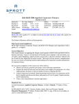
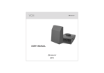
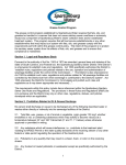
1
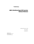
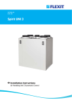
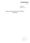
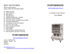
USER'S MANUAL
KITCHEN FAN IN
SOUND INSULATED CASING
KSK SERIES
2012
2
KSK
CONTENTS
1. Purpose
р. 3
2. Delivery Set
р. 3
3. Main Technical Specifications
р. 3
4. Designation key
р. 3
5. Safety Requirements
р. 5
6. Installation and Operation Instructions
р. 5
7. Fan Structure
р. 6
8. Fan Installation
р. 6
9. Connection to power mains
р. 8
10. Troubleshooting and fault handling
р. 10
11. Storage Regulations
р. 10
12. Manufacturer's Warranty
р. 11
13. Acceptance Certificate
р. 12
14. Warranty Card
р. 12
3
KSK
PURPOSE
KSK is a centrifugal fan in a sound insulated casing with a swing-out
motor-impeller block and the motor positioned outside the air stream.
KSK fans are intended for exhaust ventilation of premises with the
temperatures up to 100° C and are used for household and restaurant
exhaust systems; venting gases generated while welding;
and ventilation of industrial bakeries.
The units meet the requirements of IP54 hazardous parts access and
water ingress protection standard.
The motor insulation is F rated.
DELIVERY SET
The delivery set includes:
Fan - 1 piece;
User's manual;
Packing.
MAIN TECHNICAL SPECIFICATIONS
The fan designations, their parameters and connecting dimensions are
given in Tables 1 and 2 as well as on Fig. 1.
DESIGNATION KEY
Power Mains Specifications:
E - single phase
D - three-phase
Number of Pole Terminals:
4
Outlet Duct Diameter:
150; 160; 200; 250 mm.
Fan Name:
KSK - centrifugal fan in noise reduction casing
Designation Example
KSK 160 4Е - centrifugal fan in a sound-insulated casing with 160 mm
spigot and a single-phase four-pole motor.
4
KSK
D
L4
L3
D
H
D
H1
H1
L4
L1
B
B1
L
L2
Fig. 1
Dimensions, mm
Fan Type
D
B
B1
H
H1
L
L1
L2
L4
150 410 330 540 365 525 500 470 475 205
KSK 160 4Å / KSK 160 4D
160 410 330 540 365 525 500 470 475 205
KSK 200 4Å / KSK 200 4D
200 485 365 600 425 625 600 570 515 235
KSK 250 4Å / KSK 250 4D
250 575 435 665 505 700 675 645 620 285
Table 1
Maximum
Rotation speed,
0
Temperature, C
min-1
Capacity,
3
m /h
Voltage,
V/Hz
Current,
А
Power,
W
KSK 150 4Å
630
230/50
1,7
180
1450
100
KSK 150 4D
670
380/50
0,6
180
1455
100
KSK 160 4Å
700
230/50
1,7
180
1450
100
KSK 160 4D
730
380/50
0,6
180
1455
100
KSK 200 4Å
1600
230/50
3,0
550
1475
100
KSK 200 4D
1650
380/50
2,0
750
1465
100
KSK 250 4Å
3400
230/50
11,0
1500
1500
100
KSK 250 4D
3500
380/50
3,4
1500
1470
100
Fan Type
Table 2
5
4
1
2
3
6
1 - casing;
2 - electric motor;
3 - terminal box;
4 - impeller;
Fig. 2
L3
KSK 150 4Å / KSK 150 4D
7
5 - spigot;
6 - load bearing frame RN-KSK;
7 - vibration damper.
5
KSK
SAFETY REQUIREMENTS
Disconnect the product from the power mains prior to all operations
specific to connection, setup, maintenance and repair.
Fan maintenance and installation shall only be performed by professional
electricians qualified for unassisted operations with electrical installations
up to 1000 V after careful study of the present manual.
All the fans are not designed for out-of-the-box operation and require
connection to the air ducts.
The ducts are connected to the fan on both sides.
If the fan is mounted outdoors it should be protected against the elements
and moisture (e.g. by means of a top hood above the fan).
Prior to connecting the fan to the power mains check for visible damage
of the casing and any foreign objects in the fan casing which may damage
the impeller blades.
The fan may only be used as intended. No modifications or alterations
are allowed. The fan is not intended for operation in areas with an explosive
and/or chemically aggressive environment.
Take all the reasonable steps to prevent back draft of gas from any units
which utilize gas or direct flame.
The fan is rated for connection to single-phase ac 230 V / 50 Hz and
three-phase 380/50 Hz power mains.
INSTALLATION AND OPERATION INSTRUCTIONS
Prior to the fan installation check the integrity of the power supply wires
and for any obstructions to the impeller wheel.
It is recommended that flexible inserts are mounted on both sides of the fan
upstream and downstream.
Mount the fan in such a way that the arrow on the fan casing matches the
air flow direction in the system.
The fan requires reliable grounding.
6
KSK
FAN DESIGN
The fan casing is made of galvanized steel soundproofed on the inside
with 50 mm thick mineral wool.
The pivot design of the swing-out motor-impeller unit ensures easy
access to the fan internals for quick and efficient cleaning.
The inlet and outlet fitting diameters match the standard duct sizes.
The fittings have rubber seals.
The fan in mounted on RN-KSK load-bearing frames with integral vibration
dampers and mounting brackets KM-KSK (ordered separately).
The fan benefits from a steel high-performance centrifugal impeller with
forward-curved vanes.
The impeller is mounted on the electric motor shaft and is jointly balanced
statically and dynamically.
The high-performance single-phase or three-phase electric motor with a
squirrel-cage rotor is completely maintenance-free.
The power is adjusted by means of transformer control units.
The fan is connected to the power mains via the terminal box mounted
on the electrical motor.
Provide an additional electric cable length to ensure unobstructed
opening of the swing-out motor-impeller unit.
FAN INSTALLATION
Check the unpacked fan casing (no dents or deformations are allowed)
and make sure that the impeller has smooth rotation and does not touch
the flange and the casing.
Follow the safety regulations during the make-ready procedures and
operation.
Fig. 3 shows the fan wall mounting option using KM-KSK mounting
brackets.
KM-KSK mounting brackets are not included in the delivery package.
Ensure a direct air duct section of at least one air duct diameter long
on the inlet side and at least three air duct diameters long on the
outlet side.
The fans undergo continuous design improvement - therefore, some
models may slightly differ from those described in the manual.
7
KSK
1
2
3
4
5
6
Fig. 3
8
KSK
ELECTRICAL MAINS CONNECTION
Disconnect the fan from the power supply prior to any work
on the unit.
All the electrical connections of the fan must be made by a qualified
electrician.
The nominal values of electrical parameters are given on the fan
manufacturer's label.
Any tampering with the internal connections is prohibited and will
void the warranty.
The power supply depends on the fan type: 230V/50 Hz single-phase or
380V/50Hz three-phase AC voltage.
The fan connections (cables and wires) must be durable, insulated and
heat-resistant.
The external lead-in (230V/50Hz or 380V/50Hz) must be equipped with
an automatic circuit breaker integrated into the stationary wiring.
The position of QF external switch must ensure free access for quick
power-off of the fan.
The recommended automatic breaker nominal current and conductor
sections are given in Table 3.
The power conductor section is 1.5 mm2.
However, the conductor section selection shall account for the maximum
permissible wire heating which depends on the wire type, its insulation,
length and installation method (i.e. overhead, duct layout or inside the walls).
The trip current shall be consistent with the current consumption of the
unit as given in Table 2.
The fan connections shall be made on the terminal block mounted inside
the terminal box on the fan casing in strict accordance with the electrical
connection diagram and terminal designations.
The label with terminal designations is inside the terminal box.
The QF automatic switch is not included in the delivery package and is
installed by the user.
The fan wiring diagrams are given on Fig.4 and 5.
Connect the fan to the power mains as shown on Fig.6.
9
KSK
Automatic switch rated current (recommended) and conductor section
Fan Type
Automatic switch
rated current, A
Recommended cable, n x S,
where n is the number of wires
2
and S is the section in mm .
KSK 150 4Å
2
2 õ 1,5
KSK 150 4D
1
3 õ 1,5
KSK 160 4Å
2
2 õ 1,5
KSK 160 4D
1
3 õ 1,5
KSK 200 4Å
8
2 õ 1,5
KSK 200 4D
3,15
3 õ 1,5
KSK 250 4Å
12,5
2 õ 1,5
KSK 250 4D
4
3 õ 1,5
Table 3
Connection Diagram for fans KSK 150 4E, KSK 160 4E, KSK 200 4E,
KSK 250 4E with Single-Phase Motor to AC Mains
Ñ1
QF
~230 V
50 Hz
N
W2
L
U1
U2
V2
X1
V1
where
Х1 - fan terminal block;
S1 condenser;
QF - automatic switch
(not included in the delivery package)
W1
Fig. 4
Wiring Diagram for fans KSK 150 4D, KSK 160 4D, KSK 200 4D,
KSK 250 4D with Three-Phase Motor to AC Mains
W2
U2
V2
X1
U1
V1
W1
where
Х1 - fan terminal block;
QF - automatic switch
(not included in the delivery package)
QF
L1
L2
L3
~380 V / 50 Hz
Fig. 5
10
KSK
1
2
3
4
Fig. 6
TROUBLESHOOTING
MALFUNCTION
PROBABLE REASON
ELIMINATION METHOD
Fan doesn't work
No power
Check the power switch.
Check electrical connections
against the wiring diagram.
Noisy operation
Fan impeller out of balance
Clean the impeller.
STORAGE REGULATIONS
The fan should be stored in the original packing in a ventilated area at
temperatures from +5°C to +40°C and relative air humidity not more than
80% (at Т=20°C).
11
KSK
MANUFACTURER'S WARRANTY
We hereby declare that the following product complies with the essential
protection requirements of Electromagnetic Council Directive
2004/108/EC, 89/336/EEC and Low Voltage Directive 2006/95/EC,
73/23/EEC and CE-marking Directive 93/68/EEC on the approximation
of the laws of the Member States relating to electromagnetic compatibility.
This certificate is issued following test carried out on samples of the
product referred to above.
While purchasing the product the customer accepts the following
warranty terms:
Manufacturer hereby guarantees normal operation of the fan for 24 months
from the date of resale, subject to the compliance with transport, storage,
mounting and operation rules.
In case of no confirmation of sales date the warranty period is calculated
from the production date.
All the units and components belonging to the faulty unit and replaced
within the warranty period shall be covered by the previous warranty
period and general warranty conditions.
Thus the warranty period is neither extended nor renewed for the replaced
components or the fan.
In case of any failures due to faulty manufacturing during warranty period,
the Customer has the right to have the goods replaced at the
manufacturing facility.
Replacements are offered at Seller.
The accessories operated together with the unit, both included and not
included into the delivery list as well as other equipment operating jointly
with the unit shall not be covered by the warranty.
No warranty for compatibility of the fans with other producers' goods.
Only manufacturing defects are covered by the warranty terms.
All the defects and faults resulting from mechanical effect during operation
process or natural wear-and-tear shall not be covered by the warranty
conditions.
The malfunctions caused by violence of operation, servicing and
maintenance guidelines either by Customer or third parties or caused by
unauthorized design modifications shall not be covered by warranty.
NO LIABILITY FOR THE RELATED DAMAGES:
The manufacturer is not responsible for any mechanical or physical
damages resulting from the manual requirements violence, the unit
misuse or gross mechanical effect.
The indirect damages such as re-installation or re-connection of the unit,
direct or indirect losses etc. related to the unit replacement shall not be
indemnified.
Mounting/dismantling, connection/disconnection and setup of the unit
shall not be covered by the warranty. The contractor in charge for quality
of mounting, electric mounting and adjustment works shall be responsible
for the warranty thereof.
In any case the indemnity amount shall not exceed the actually paid value
for the defective unit price.
12
KSK
ACCEPTANCE CERTIFICATE
The fan is recognized as serviceable.
Model
VENTS KSK ______________
(tick the proper model)
Date of production
Stamp of the acceptance inspector
Sold by
name of the vendor, stamp of the shop
Date of sale
WARRANTY CARD
V72EN-02