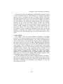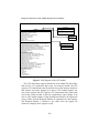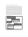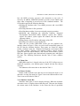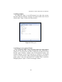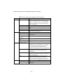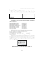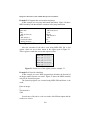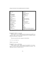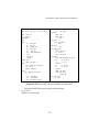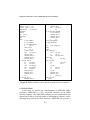
1
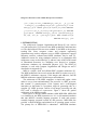
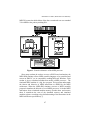
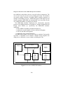
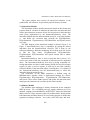
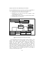
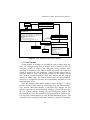
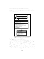
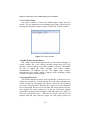
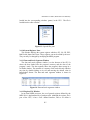
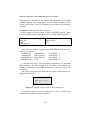
The Islamic University Journal (Series of Natural Studies and Engineering) Vol.15, No. 2, pp 95-126, 2007, ISSN 1726-6807, http://www.iugaza.edu.ps/ara/research/ Design of a Microsoft Version of MIPS Microprocessor Simulator Mohammad A. Mikki*, Mohammed R. El-Khoudary Electrical and Computer Engineering Department, Faculty of Engineering , ISLAMIC University of Gaza, P.O. Box-108, Gaza, Palestine Tel: +970-8-2823311, Fax: +970-8-2823310, E- mail: [email protected], [email protected] ABSTRACT: We describe the implementation of a MIPS Simulator called MIPSSIM. MIPS-SIM is a GUI, Java-based simulator for the MIPS assembly language. MIPS, the computer architecture is widely used in industry and is the basis of the popular textbook Computer Organization and Design by David Patterson and John Hennessy, used at over 400 universities. The third edition of this text (published by Morgan Kaufmann in 2005) uses standard 32-bit MIPS as the primary teaching ISA. The MIPS-SIM simulator has been implemented for educational purposes with characteristics that are especially useful to undergraduate computer science and engineering students and their instructors who use the above textbook. MIPSSIM should be useful in courses such as computer organization and architecture, assembly language programming, and compiler writing. MIPS-SIM implements almost the entire MIPS32 assembler-extended instruction set. MIPS-SIM also provides a simple debugger and minimal set of operating system services. We test MIPS-SIM simulator by running several MIPS assembly programs. Results prove the accuracy, correctness, effectiveness and usefulness of MIPSSIM. KEYWORDS MIPS processors, Simulator, Assembly language, Instruction set, Assembler ﺍﻟﺩﻗﻴﻘﺔMIPS ﺘﺼﻤﻴﻡ ﻤﺤﺎﻜﻲ ﻟﻤﻌﺎﻟﺠﺎﺕ ﺍﻟﺫﻱ ﻫﻭ ﻋﺒﺎﺭﺓ ﺒﺭﻨﺎﻤﺞ ﻤﺤﺎﻜﺎﺓ ﻟﻤﻌﺎﻟﺠﺎﺕMIPS-SIM ﻨﻘﻭﻡ ﻓﻲ ﻫﺫﺍ ﺍﻟﺒﺤﺙ ﺒﻭﺼﻑ ﺘﺼﻤﻴﻡ:ﺍﻟﻤﻠﺨﺹ ﻭ ﻴﻌﻤل ﻀﻤﻥ ﺒﻴﺌـﺔ ﺭﺴـﻭﻤﻴﺔ ﻟﻠﺘﻔﺎﻋـل ﻤـﻊJava ﻤﻜﺘﻭﺏ ﺒﻠﻐﺔMIPS-SIM ﺍﻥ ﺒﺭﻨﺎﻤﺞ.MIPS ﻋﺒﺎﺭﺓ ﻋﻥ ﻫﻴﻜﻠﻴﺔ ﺤﺎﺴﻭﺏ ﺸﺎﺌﻊ ﺍﻷﺴﺘﺨﺩﺍﻡ ﻓﻲ ﺍﻟﺼﻨﺎﻋﺔ ﻭ ﻫﻭ ﺍﻷﺴﺎﺱ ﻟﻠﻜﺘﺎﺏ ﺍﻟﺠﺎﻤﻌﻲMIPS . ﺍﻟﻤﺴﺘﺨﺩﻡ ﻟﻠﻤﺅﻟﻔﻴﻥ ﺩﻴﻔﻴﺩ ﺒﺎﺘﺭﺴﻭﻥ ﻭ ﺠﻭﻥ ﻫﻴﻨﻴﺴﺴـﻲComputer Organization and Design ﺍﻟﻤﺸﻬﻭﺭ ﺍﻥ ﺍﻟﻁﺒﻌﺔ ﺍﻟﺜﺎﻟﺜﺔ ﻤﻥ ﻫﺫﺍ ﺍﻟﻜﺘﺎﺏ ﻤﻥ ﺩﺍﺭ ﺍﻟﻨﺸﺭﻤﻭﺭﺠﺎﻥ. ﺠﺎﻤﻌﺔ400 ﺍﻟﻤﺴﺘﺨﺩﻡ ﻜﻜﺘﺎﺏ ﻤﻘﺭﺭ ﻓﻲ ﺃﻜﺜﺭ ﻤﻥ ﻟﻘﺩ ﺘﻡ. ﻜﻬﻴﻜﻠﻴﺔ ﺭﺌﻴﺴﻴﺔ ﻟﻬﻴﻜﻠﻴﺔ ﻤﺠﻤﻭﻋﺔ ﺍﻟﺘﻌﻠﻴﻤﺎﺕMIPS32 ﻴﺴﺘﺨﺩﻡ ﺍﻟﻤﻌﺎﻟﺞ2005 ﻜﻭﻓﻤﺎﻥ ﻓﻲ ﺍﻟﻌﺎﻡ ﻷﻏﺭﺍﺽ ﺘﻌﻠﻴﻤﻴﺔ ﺒﺨﺼﺎﺌﺹ ﻤﻔﻴﺩﺓ ﻟﻁﻼﺏ ﺍﻟﺒﻜﺎﻟﻭﺭﻴﻭﺱ ﻓﻲMIPS-SIM ﺘﺼﻤﻴﻡ ﺒﺭﻨﺎﻤﺞ ﺍﻟﻤﺤﺎﻜﺎﺓ ﻋﻠﻭﻡ ﺍﻟﺤﺎﺴﻭﺏ ﺃﻭ ﻫﻨﺩﺴﺔ ﺍﻟﺤﺎﺴﻭﺏ ﻭ ﻤﺩﺭﺴﻴﻬﻡ ﻋﻠﻰ ﻭﺠﻪ ﺍﻟﺨﺼﻭﺹ ﺍﻟﺫﻴﻥ ﻴﺴﺘﺨﺩﻤﻭﻥ ﺍﻟﻜﺘﺎﺏ ﺃﻋﻼﻩ Design of a Microsoft Version of MIPS Microprocessor Simulator ﻓﻲ ﻤﺴﺎﻗﺎﺕ ﻤﺜـل ﻫﻴﻜﻠﻴـﺔ ﻭ ﻋﻤـﺎﺭﺓMIPS-SIM ﻴﻤﻜﻥ ﺍﺴﺘﺨﺩﺍﻡ ﺒﺭﻨﺎﻤﺞ .ﻜﻜﺘﺎﺏ ﺩﺭﺍﺴﻲ ﻤﻘﺭﺭ ﻴﻘﻭﻡ ﺒﺭﻨـﺎﻤﺞ ﺍﻟﻤﺤﺎﻜـﺎﺓ.( compilers) ﻭ ﺘﺼﻤﻴﻡ ﺍﻟﻤﺘﺭﺠﻤﺎﺕ، ﺍﻟﺒﺭﻤﺠﺔ ﺒﻠﻐﺎﺕ ﺍﻟﺘﺠﻤﻴﻊ،ﺍﻟﺤﺎﺴﺒﺎﺕ ﻜﻤﺎ ﻴﻘﻭﻡ ﺒﺭﻨﺎﻤﺞ ﺍﻟﻤﺤﺎﻜﺎﺓ. MIPS32 ﺒﻤﺤﺎﻜﺎﺓ ﻜل ﻤﺠﻤﻭﻋﺔ ﺍﻟﺘﻌﻠﻴﻤﺎﺕ ﺍﻟﺘﻭﺴﻌﻴﺔ ﻟﻤﻌﺎﻟﺞMIPS-SIM ﺒﺘﻭﻓﻴﺭ ﺃﺩﺍﺓ ﺒﺴﻴﻁﺔ ﻟﺘﺼﺤﻴﺢ ﺃﺨﻁﺎﺀ ﺍﻟﺒﺭﻤﺠﺔ ﻜﻤﺎ ﻴﺤﺘﻭﻱ ﻋﻠﻰ ﻤﺠﻤﻭﻋـﺔ ﻤﺤـﺩﻭﺩﺓ ﻤـﻥMIPS-SIM ﻭ ﺫﻟﻙ ﺒﺘﻨﻔﻴﺫ ﻋﺩﺓ ﺒﺭﺍﻤﺞMIPS-SIM ﻗﻤﻨﺎ ﺒﺎﺨﺘﺒﺎﺭ ﺒﺭﻨﺎﻤﺞ ﺍﻟﻤﺤﺎﻜﺎﺓ.ﺍﻟﺒﺭﺍﻤﺞ ﺍﻟﺨﺩﻤﺎﺘﻴﺔ ﻟﻨﻅﻡ ﺍﻟﺘﺸﻐﻴل ﺩﻗﺔ ﻭ ﺼﺤﺔ ﻭ ﻓﻌﺎﻟﻴﺔ ﻭ ﻓﺎﺌﺩﺓ ﻟﻘﺩ ﺍﻅﻬﺭﺕ ﻨﺘﺎﺌﺞ ﻫﺫﻩ ﺍﻟﺘﺠﺎﺭﺏ .MIPS assembly ﻤﻜﺘﻭﺒﺔ ﺒﻠﻐﺔ MIPS-SIM ﺒﺭﻨﺎﻤﺞ ﺍﻟﻤﺤﺎﻜﺎﺓ ﺘﺼﻤﻴﻡ 1. INTRODUCTION The widely-used Computer Organization and Design [1] text, used at over 400 universities [2] is based on the MIPS architecture and instruction set. The third edition of this text uses standard 32-bit MIPS as the primary teaching ISA. Since computer science and computer engineering departments may not have adequate access to MIPS equipment to support laboratory activities, software-based MIPS simulators may be used [2]. Additional reasons for using simulation software in an organization and architecture course are described in [3], and two issues of the ACM Journal of Educational Resources in Computing were devoted to computer architecture simulators for educational purposes [4,5]. The SPIM [6] simulator is used with Computer Organization and Design text and is described in its Appendix [2]. MIPS is a simple, clean, and efficient RISC computer architecture [1]. The MIPS architecture has several variants that differ in various ways (e.g., the MIPS32 architecture supports 32-bit integers and addresses, and the MIPS64 architecture supports 64-bit integers and addresses). The architecture of the MIPS computers is simple and regular, which makes it easy to learn and understand. The processor is a RISC processor that contains 32 general-purpose 32-bit registers and a well-designed instruction set that makes it a propitious target for generating code in a compiler [6]. MIPS processor consists of an integer processing unit (the CPU) and a collection of coprocessors. Figure 1 shows the general architecture of the MIPS processor. In this paper we design a MIPS simulator called MIPS-SIM. MIPS-SIM is a simulator for the MIPS instruction set. It is a self-contained simulator that runs MIPS32 assembly language programs. It reads and executes assembly language programs written for this processor. MIPS-SIM also provides a simple debugger and minimal set of operating system services. The primary use of MIPS-SIM is educational. MIPS-SIM simulates 96 Mohammad A. Mikki, Mohammed R. El-Khoudary MIPS32 because the third edition of the above mentioned text uses standard 32-bit MIPS as the primary teaching ISA. Figure 1: General architecture of the MIPS processor Since many students do not have access to a RISC-based workstation, the MIPS-SIM simulator allows MIPS assembly-language to be assembled and run on an IBM PC (or its compatibles) running Microsoft Windows. Each student is given a simulated machine that models a MIPS processor. The simulated MIPS machine is a big Java program. This program understands the format and behavior of MIPS instructions as defined by the MIPS architecture. When the MIPS-SIM simulator executes a MIPS assembly program it simulates the behavior of a real MIPS processor. It fetches MIPS instructions from a simulated machine memory, decodes them and executes them. It transforms the state of the simulated memory and simulated machine registers according to the defined meaning of the instructions in the MIPS architecture specification [7]. 97 Design of a Microsoft Version of MIPS Microprocessor Simulator Obviously, there are already several very good simulators. The main difference with our simulator is that it is being implemented in Java and is intended for academic use. Although running assembly programs on workstations that contain the MIPS hardware is significantly faster, we use a simulator because these workstations are not generally available. Another reason is that these machines will not persist for many years because of the rapid progress leading to new and faster computers. In addition, simulators can provide a better environment for low-level programming than an actual machine because they can detect more errors and provide more features than an actual computer [6]. Finally, simulators are useful tools for studying computers and the programs that run on them. Because they are implemented in software, not silicon, they can be easily modified to add new instructions, build new systems such as multiprocessors, or simply to collect data [6]. The MIPS-SIM simulator implements the educationally important portions of the MIPS instruction set utilized by third edition of the Computer Organization and Design textbook [1]. Specifically, the MIPSSIM simulator implements complete MIPS instructions, complete translation of MIPS instructions to MIPS machine language, advanced exception handling for better and faster debugging, full size data and stack segments, and support for most pseudo instructions. Pseudo-instructions are expanded into one or more native MIPS instructions by the assembler. The MIPS-SIM simulator is written in Java 1.4.2, and runs on IBM PCs (or its compatibles) under Microsoft Windows environment. The rest of the paper is organized as follows: Section 2 presents related work. Section 3 presents the details of the implementation of MIPS-SIM. Section 4 presents the pseudo code of MIPS-SIM. Section 5 validates the design of the proposed simulator. Finally, section 6 concludes the paper. 2. RELATED WORK A number of MIPS simulators have been developed over the years. Most of these simulators can be classified by a small number of categories: those designed for research use (e.g. MIPSI), those that focus on certain MIPS architectural features such as pipelines (e.g. WebMIPS [8], SmallMIPS [9], RTLSim[10]), those that depend on SPIM (e.g. MIPSASM, TinyMIPS), and general purpose simulators [2]. Examples of the latter include MipsIt [11] and SPIM [6]. Most MIPS simulators include features for visualizing and/or animating MIPS components. SPIM is without doubt the most widely 98 Mohammad A. Mikki, Mohammed R. El-Khoudary known and used MIPS simulator, serving both education and industry [2]. In the following, we describe some of the existing MIPS simulators. In [9] the authors create a simulator for the MIPS architecture. They call their instruction set Small-MIPS, which is a subset of MIPS R2000 instruction set, plus some interesting instructions that they added. MIPS assembler is created as part of the pipeline simulator project. It takes in a human-readable assembly file and translates it into a data structure that is only readable to the pipeline simulator. Not all of MIPS2000 instructions are supported. In [12] MIPS SDE (Software Development Environment) which is a cross-development system for MIPS architecture processors is described. It produces code for a variety of MIPS-based platforms and also simulator platforms. It is intended for building and debugging statically-linked applications to run in embedded environments on "bare-metal" CPUs or light-weight operating systems. In [13] MIPSI; MIPS simulator is developed. MIPSI is an instructionlevel simulator for the MIPS family of processors. Its main attributes are simplicity and robustness. MIPSI runs on big or little Endian MIPS boxes and on Alpha platforms. In [6] SPIM MIPS simulator is described. SPIM is a self-contained simulator that runs MIPS R2000/R3000 assembly language programs. It reads and immediately executes assembly language code for this processor (it does not execute binary programs). SPIM provides a simple debugger and minimal set of operating system services. SPIM implements almost the entire MIPS assembler-extended instruction set for the R2000/R3000. SPIM implements both a simple, terminal-style interface and a window interface. Finally, in [2,14] MARS (MIPS Assembler and Runtime Simulator) is described. MARS is a lightweight Interactive Development Environment (IDE) for MIPS assembly language programming. It is intended for educational-level use with Patterson and Hennessy's Computer Organization and Design, third edition. 3. DESIGN APPROACH OF MIPS-SIM In this section we describe in detail the design of the MIPS-SIM simulator. MIPS-SIM is a friendly GUI, Java-based simulator for the MIPS assembly language. It supports interactive editing; compilation; execution and debugging of MIPS assembly programs. MIPS-SIM features WYSIWYG on-the- spot modification where the user can view and edit the register file and data and stack segments. MIPS-SIM design is made with 99 Design of a Microsoft Version of MIPS Microprocessor Simulator the scalability in mind where the user can easily add new instructions. The user can also reset the processor just by clicking one button. The simulator can model parallel execution of multiple MIPS assembly programs on multiple virtual MIPS processors. MIPS-SIM supports both single step and normal execution. MIPS-SIM also automatically saves work done by the user. MIPS-SIM includes a complete user manual. The MIPS-SIM simulator implements the educationally important portions of the MIPS instruction set utilized by Computer Organization and Design, third Edition [1]. Specifically, the MIPS-SIM simulator implements: • Entire MIPS32 assembler-extended instruction set. • Advanced exception handler for better and faster debugging. • Full size data and stack Segments. • Support for most pseudo instructions. The MIPS-SIM program is divided into software modules. Each module represents a component in the simulator. Modular design simplifies the deign process, and makes it easy to enhance and debug the code. Instructions Module CPU Module Memory Module Control Module Lexical and Syntax Analysis Module Figure 2: Overview of MIPS-SIM modules 100 Graphical User Interface (GUI) Module Mohammad A. Mikki, Mohammed R. El-Khoudary An overview of the main components of MIPS-SIM is shown in Figure 2. The CPU module is the core of the simulator. It is in charge of processor functions where it coordinates the tasks of all other modules. The lexical and syntax analysis module does lexical and syntax analysis of assembly files and produces a data structure that represents the MIPS instructions of the code segment. The instructions module updates the data structure generated by the lexical and syntax analysis module and classifies instructions based on their format and prepares them for execution. The memory module simulates the random access memory (RAM) and the processor's registers. The control module executes the code. Finally, the GUI module is used to support the interfacing between the user and the simulator. It displays the contents of the registers and other useful information. In the following subsections we describe each module in more detail. 3.1 CPU Module CPU module is the core of the simulator. It simulates a real MIPS processor. CPU module coordinates the tasks of all other modules. The CPU module supports the following functions. First, setting and displaying the values of the registers in the register file. Register values are displayed in the register file pane in the GUI. Second, setting/Resetting and displaying the values of the special registers LO, HI, PC, EPC, BadVAddr, Status and cause registers. Third, resetting the CPU to its initial state. Fourth, setting and displaying the code (text), data and stack segments. Fifth, accessing and updating memory locations. Sixth, displaying memory locations in the memory pane in the GUI. Seventh, editing the files in the editor window. Eighth, handling exceptions. Ninth, modeling of parallel virtual MIPS processors, i.e., the MIPS-SIM runs as a parallel machine with multiple MIPS processors. In this mode, multiple MIPS assembly programs could run simultaneously on multiple virtual MIPS processors. The UML diagram of the CPU module is shown in Figure 3. In Figure 3 MipsCPU class extends an Observable class; implements an Observer class, and contains a RegisterController class. These classes do the whole module interaction coordination. For interactions from MipsCPU to GUI, the Observable class is used. 101 Design of a Microsoft Version of MIPS Microprocessor Simulator Observable -observers : ArrayList MipsCPU -dataSegment : RandomAccessMemory -registerFile : RegisterFile -instructionFactory : InstructionsCacheProxy -controlUnit : ControlUnit -symbolTableManager : SymbolTableManager -lexicalAnalyzer : LexicalAnalyzer -syntaxAnalyzer : SyntaxAnalyzer -sysCallIn : String -sysCallOut : String -RegisterController : RegisterController +registerDataSegment(in dataSegment : RandomAccessMemory) +registerControlUnit(in ControlUnit : ControlUnit) +registerInstructionsFactory(in instructionsFactory : InstructionsCacheProxy) +registerRegisterFile(in registerFile : RegisterFile) +registerSymbolTableManager(in symbolTableManager : SymbolTableManager) +registerLexicalAnalyzer(in lexicalAnalyzer : LexicalAnalyzer) +registerSyntexAnalyzer(in syntaxAnalyzer : SyntaxAnalyzer) +registerRegisterController(in graphical : Object) : RegisterController +loadProgram(in path : String) +compileProgram() +getLexicalAnalysis() : StringBuffer +getSyntaxAnalysis() : ArrayList +getInstruction(in instruction : String) : InstructionNode +getSymbolLocation(in label : InstructionNode) : InstructionNode +getMemoryWord(in address : long) : MemoryWord +getProgramCounter() : String +getRegisterValue(in registerNumber : int) : String +getMaxExecutionTime() : long +getSyscallIn() : String +getSyscallOut() : String +getRegisterController() : RegisterController +setRegisterValue(in registerNumber : int, in registerValue : String) +setSymbol(in label : String, in location : InstructionNode) +setMaxExecutionTime(in timeInMillis : long) +setProgramCounter(in newLocation : InstructionNode) +setSyscallOut(in sysout : String) +setSyscallIn(in sysin : String) +advanceProgramCounter() +execute() +executeSingle() +resetCPU() +synchronizeState() +sysCall(in sysCallNo : int) +notifyObservers() +registerObserver(in observer : Observer) +removeObserver(in observer : Observer) «interface» Observer +synchronizeState() RegisterController -registerFields : Object [] +getRegisterValues() : String [] +setRegisterValues() : String [] Figure 3: UML diagram of the CPU module The GUI components register themselves in the MipsCPU Observable, and wait for it to synchronize their states. For memory module, the CPU registers GUI components in the Observable class of the memory module so that memory may report changes in its state to CPU module anytime. For text (code) segment, the CPU registers GUI components in the Observable class of the control module so that text segment may report changes in its state to CPU module anytime. Using the RegisterController, the register file can get values from the RegisterController to synchronize its state anytime. The RegisterController is notified to get values from the register file whenever a change in these registers occurs. 102 Mohammad A. Mikki, Mohammed R. El-Khoudary 3.2 Lexical and Syntax Analysis Module Compilers use two or more phases of analysis to convert code from source format into target format. MIPS-SIM implements two of these phases which are the lexical (linear) analysis phase and the syntax analysis phase. MIPS-SIM ignores the semantic analysis phase because it is not necessary in assemblers. Lexical and syntax analysis are implemented within the lexical and syntax analysis module. Lexical and syntax analysis module consists of two analyzers: lexical analyzer and syntax analyzer. Lexical and syntax analysis module builds a valid structured code representation of the MIPS assembly instructions that is ready to be executed. Lexical analyzer converts code into a stream of characters, and then analyzes it. It checks keywords, constants, and extracts undefined words used in the code and reports errors in the code (undefined keywords, undefined numbers). The lexical analyzer is in charge of analyzing the code, checking for lexical errors, and preparing the code for execution. Syntax analyzer takes the result generated by the lexical analyzer and checks the correctness of keywords, variables, and constants. It reports syntax errors in the code if they exist. The UML diagram of the lexical and syntax analysis module is shown in Figure 4. In Figure 4; the FileLoader class loads a specified MIPS assembly file (passed to it by the CPU module as a StringBuffer) into the text (code) segment and prepares it for compilation, execution and debugging. It then passes it to the lexical analyzer. The LexicalAnalyzer class first removes all characters that are not part of the code including arrows, comas, dots, and white-spaces to prepare the code for the lexical analysis. Lexical analyzer then starts the analysis process by breaking code into tokens separated by characters (e.g. arrows, comas, dots, and white-spaces). It then passes these tokens to the token identifier. After the identification of every token, the lexical analyzer generates a formatted XML file to be used by the syntax analyzer. Each line in the XML file corresponds to one MIPS instruction in the assembly file. The lexical analyzer does not check the correctness of the structure of the generated XML file. The lexical analyzer also generates a symbol table (implemented through the SymbolTableManager class) that contains unresolved references (labels and global variables). It is the responsibility of the syntax analyzer to resolve these references. Each entry in the symbol table consists of three values: unresolved reference, type (CODE_LOCATION or MEMORY_LOCATION), and the physical location in memory. 103 Design of a Microsoft Version of MIPS Microprocessor Simulator Syntax analyzer (implemented through the SyntaxAnalyzer class) uses the XML file generated by the lexical analyzer as its input. It searches this file for the pre execution block which exists before or after the code. This block is used to initialize memory data segment. After the syntax analyzer finds this block; it saves all its values in the memory data segment. If there is a label in this block, the syntax analyzer adds it to the symbol table with the type MEMORY_LOCATION. After all data segment labels and values are inserted in the symbol table, the syntax analyzer begins fetching instruction lines from the XML file, one by one. It then creates InstructionNode ArrayList (one InstructionNode per MIPS instruction) and fills their fields with data from the corresponding line in the XML file. Any pseudo instruction is converted into MIPS real instructions (implemented through the PsuedoInstruction class). Branching and jumping labels in the XML file are added to the symbol table with the type CODE_LOCATION. As an output of the syntax analyzer, an ArrayList structure of InstructionNode is generated. SymbolTableManager -symbolTable : String [][] +addSymbol(in label : String, in type : int, in location : long) +getSymbol(in label : String) : long SyntaxAnalyzer -fromLexicalAnalyzer : StringBuffer FileLoader +setCodeFromLexicalAnalyzer(in code : StringBuffer) -checkInstructionSyntax(in instruction : InstructionNode) -addSymbol(in label : String, in location : InstructionNode) +analyzeCode() : ArrayList -currentFile : File +loadProgram(in String path) +getCurrentFile() : StringBuffer PseudoInstruction -substituteInstructions : String LexicalAnalyzer -fileLoader : FileLoader -currentProgram : StringBuffer +loadProgram(in path : String) : StringBuffer -removeUnwantedCharacters() +identifyToken(in token : String) : int -isKeyWord(in token : String) : boolean -isConstant(in token : String) : boolean -isOther(in token : String) : boolean -isRegister(in token : String) : boolean +analyzeProgram() : StringBuffer +convertToInstructions() +setPreviousNode(in previousNode : InstructionNode) +getPreviousNode() : InstructionNode Figure 4: UML diagram of the lexical and syntax analysis module 104 Mohammad A. Mikki, Mohammed R. El-Khoudary The syntax analyzer then resolves all unresolved references in the symbol table. All references are given their physical memory locations. 3.3 Instructions Module The instructions module classifies instructions based on their format and prepares them for execution. It initializes the instruction execution units and caches (puts instruction executors objects for fast retrieval in the instruction cache proxy implemented by the InstructionCacheProxy class). The instruction module takes the InstructionNode ArrayList as an input, updates it and builds five execution units (through the ITypeInstruction, RTypeInstruction, JTypeInstruction, NULLInstruction, and Syscall classes) as a result. The UML diagram of the instructions module is shown in Figure 5. In Figure 5, InstructionsFactory class is responsible for getting the desired instruction from the InstructionNode ArrayList. This is done by the reflection technology. Reflection technology uses lookup in the file system to find the class names (ITypeInstruction, RTypeInstruction, JTypeInstruction, NULLInstruction, and Syscall classes) and to initiate instances of them. InstructionsCacheProxy class is used to speed the above process. It is used to save much of the time consumed on reflection process mentioned above. The InstructionsCacheProxy does this by being responsible for storing instructions in a table in main memory (RAM) for fast retrieval upon request. So after it receives requests, it looks up its own table (which is resident in RAM). If the instruction object is already there, it is returned. If not, InstructionsCacheProxy uses the InstructionsFactory to reflect this instruction from the storage device. The architecture of the MIPS instruction is defined using the MIPSInstruction interface which is implemented through five classes: ITypeInstruction, RTypeInstruction, JTypeInstruction, NULLInstruction, and Syscall. These classes further process and update the instruction node and prepare the instruction for execution by the control module. 3.4 Memory Module The simulator must implement a memory abstraction for the simulated MIPS processor. For a real MIPS processor, memory addresses are 32-bit numbers, ranging from 0x00000000 to 0xFFFFFFFF, where each individual address refers to a byte in memory (thus is byte addressable). Memory holds both instructions and data. Memory for an executing program is divided into segments according to function – text (code), static data, heap, and stack. 105 Design of a Microsoft Version of MIPS Microprocessor Simulator For our simulated processor, the word size is 32 bits, or equivalently, 4 bytes. The main memory module supports the following functions: • Modeling the text (code), data and stack segments. • Displaying the text (code), data and stack segments in their corresponding panes in the GUI. • Reading/writing a memory word/byte at a specified memory address. • Resetting memory to its empty state. InstructionsCacheProxy -Cache : Hashmap -instructionFactory : InstructionsFactory +getInstruction(in Instruction : String) : MIPSInstruction +clearCache() -$ingleInstance 1 InstructionsFactory 1 -InstructionsFactory : InstructionsFactory 1 * +getInstructionFactory() : InstructionsFactory +getInstruction(in Instruction : String) : MIPSInstruction «instance» «interface» MIPSInstruction +checkSyntax() : String +execute() +getAssimblyBitString() : String +getInstructionType() : int <<throws>> «exception» InstructionNotFoundException Syscall -assembly : String -parameters : ArrayList +checkSyntax() : String +execute() +getAssemblyBitString() : String +getInstructionType() : int ITypeInstruction RTypeInstruction JTypeInstruction NULLInstruction -upperPart : String -parameters : ArrayList +checkSyntax() : String +execute() +getAssemblyBitString() : String +getInstructionType() : int -upperPart : String -lowerPart : String -parameters : ArrayList +checkSyntax() : String +execute() +getAssemblyBitString() : String +getInstructionType() : int -upperPart : String -parameters : ArrayList +checkSyntax() : String +execute() +getAssemblyBitString() : String +getInstructionType() : int -upperPart : String -parameters : ArrayList +checkSyntax() : String +execute() +getAssemblyBitString() : String +getInstructionType() : int Figure 5: UML diagram of the instructions module The UML diagram of the memory module is shown in Figure 6. The memory module consists of two sub-modules. The first sub-module is Random Access Memory (RAM). RAM contains two segments; data segment and stack segment. RAM is implemented through the RandomAccessMemory class. The second sub-module is the register file which holds both general purpose registers and system registers. The register file module is implemented through the RegisterFile class. The Observable class in Figure 6 is included for GUI purposes. This class is in charge of notifying the GUI component that uses it of any change in memory locations and registers values. 106 Mohammad A. Mikki, Mohammed R. El-Khoudary «interface» Observer +synchronizeState() Observable -observers : ArrayList +notifyObservers() +registerObserver(in observer : MemoryObserver) +removeObserver(in observer : MemoryObserver) RegisterFile -registers : Hashmap -systemRegisters : Hashmap -registersBaseAddress : long -systemRegistersBaseAddress : long +getRegisterValue(in registerNumber : int) : String +getSystemRegisterValue(in registerNumber : int) : String +setRegisterRegisterValue(in registerNumber : int, in registerValue : String) +setSystemRegisterValue(in registerNumber : int, in registerValue : String) +isSystemRegister(in registerNumber : int) : boolean +isRegister(in registerNumber : int) : boolean +clearRegisters() +getRegisterBaseAddress(in registerNumber : int) : long +getSystemRegisterBaseAddress(in registerNumber : int) : long <<throws>> RandomAccessMemory -rootWord : MemoryWord <<throws>> +getMemoryWord(in address : long) : MemoryWord +resetRAM() * «exception» MemoryOutOfBoundException 1 MemoryWord «exception» RegisterNotFoundException <<throws>> «exception» InvalidDataException -leftChild : MemoryWord -rightChil : MemoryWord -address : long -word : String [] +insertOrGet(in requestedLocation : long) : MemoryWord +setRightWord(in rightChild : MemoryWord) +setLeftWord(in leftChild : MemoryWord) +setByte(in byteNo : int, in value : String) +setAddress(in address : long) +getByte() : String +getAddress() : long +getRightWord() : MemoryWord +getLeftWord() : MemoryWord Figure 6: UML diagram of the memory module 3.5 Control Module Control module is in charge of executing the code in either single step mode (for debugging purposes) or normal mode. Control Unit uses an instruction pointer to point to the instruction being executed. After executing an instruction; the control module increments the instruction pointer to point to the next instruction. Control module insures that no execution violations occur, and that the execution is not taking too long time. Program execution taking too long may indicate that the program entered an infinite loop. The control module takes the InstructionNode ArrayList as an input and executes the corresponding instruction of each InstructionNode object. The UML diagram of the control module is shown in Figure 7. Control module consists of three units: the ControlUnit class, the InstructionNode class, and the Observable interface. ControlUnit class manages the text segment represented by InstructionNode ArrayList. ControlUnit may clear the text segment through invoking the clearTextSegment method. The InstructionNode class is the main unit of the InstructionNode ArrayList tree. It is used by the syntax analyzer to create the InstructionNode objects. The ControlUnit class extends the Observable interface so that GUI components 107 Design of a Microsoft Version of MIPS Microprocessor Simulator can update the content of text segment pane automatically when any change in the text segment occurs. O bs erv able -observe rs : A rra yL ist + notifyO bserve rs() + re giste rO bse rver(in observe r : O bserve r) + re m oveO b se rver(in observe r : O bserve r) ControlU nit -te xtS eg m ent : A rrayList -instructionP o inter : InstructionN od e -m axE xecutio nTim e : lo ng + getR ootInstru ction () : InstructionN od e + getC urren tIn structio n() : Instru ction No de + getM axE xe cu tionTim e() : long + setM a xE xecutionT im e (in tim e InM illis : lo ng ) + setTe xtS eg m ent(in textS egm e nt : A rra yL ist) + advanceInstru ctio nP ointe r() + exe cu te () + exe cu te S ingle () + clea rTe xtS eg m en t() InstructionN ode -instru ction : S trin g -pa ra m eters : String [] + ge tIn structio nType () : int + ge tA sse m blyB itString () : String + ge tIn structio n() : S trin g [] + checkS yntax() : S tring + execute () Figure 7: UML diagram of the control module 3.6 Graphical User Interface (GUI) Module The GUI module provides the interfacing between the user and the simulator. It displays the status of the simulator. The GUI provides the user with ways to control the basic functions of the MIPS-SIM simulator. The GUI can be launched by executing the MIPS-SIM program. To close the GUI, one just needs to select the "Exit" option from the "file" submenu. Using the GUI, the user can load, run, step, restart and exit a MIPS assembly program. GUI enables users to reset/retrieve the status of the MIPS processor. This allows one not only to efficiently run the code and view the results, but also to debug the code and to be able to see exactly 108 Mohammad A. Mikki, Mohammed R. El-Khoudary how the MIPS processor processes each instruction at any cycle, if necessary. In addition, MIPS-SIM simulator provides several windows that show what is happening in several areas of the simulated machine. The GUI module supports the following functions: • Initiating the simulator with a reset MIPS processor and a new MIPS assembly file. • Providing menu bar for file operations. • Providing button toolbar for mouse-activated program operations. • Initializing and displaying the following windows: Integrated Development Environment (IDE) Window, opened files window, register file window, system register file window, and data and stack segments window. • Setting listeners for all windows and buttons of the GUI. • Providing a text editor to create/modify files. When the user invokes MIPS-SIM, he/she gets the graphical user interface shown in Figure 8. There are twelve main components (panes) of the GUI that the simulator displays. These panes are: menu bar, button toolbar, simulator status bar, integrated development environment (IDE) bar, editor window, debugger (text segment) window, console window (program input and output window), IDE window detach button, opened files pane, system registers pane, data and stack segments pane, and register file pane. The following subsections describe each of these windows (panes). 3.6.1 Menu Bar MIPS-SIM menu bar is located at the top of the GUI. It allows users to handle file operations; view different panes; compile and run files; and get user help. The submenus of the menu bar are described in Table 1. 3.6.2 Button Toolbar Button toolbar includes icons that may be used using the mouse as an alternative to using the menu bar. Figure 9 shows the button toolbar icons. These icons are described in Table 2. 3.6.3 Simulator Status Bar Simulator status pane is used to display messages. When the assembler encounters errors, it displays them within this pane. This pane also displays the current status of the simulator. It also shows the state of operations 109 Design of a Microsoft Version of MIPS Microprocessor Simulator performed by the simulator (e.g., opening a file, saving a file, compiling a file, etc.). Figure 8: MIPS-SIM Graphical User Interface (GUI) Figure 9: Button toolbar icons 3.6.4 Integrated Development Environment (IDE) Bar The IDE bar enables users to select one of the following windows: editor, debugger, and console. All of these windows are empty when the user starts the simulator. IDE enables users to interface with the running programs through these windows. These three windows are described in more detail in the following three subsections. 110 Mohammad A. Mikki, Mohammed R. El-Khoudary 3.6.5 Editor Window The MIPS-SIM editor is an ASCII-oriented text editor that operates much like Microsoft Window's Notepad. The button toolbar icons are used with the editor. Figure 10 shows the editor window. Figure 10: Editor pane 3.6.6 Debugger (text segment) Window The text segment window shows instructions both from user's program and the system code that is loaded automatically when MIPS-SIM is running. For each instruction, the address (displayed in hexadecimal format between square brackets), machine code (in hexadecimal format), and assembly language version of the instruction are displayed. A breakpoint can be set at any instruction. When stepping through program execution, a pointer points to the next instruction to be executed. This is useful for debugging purpose. Figure 11 shows the debugger window. 111 Design of a Microsoft Version of MIPS Microprocessor Simulator Table 1: Description of the submenus of the menu bar Submenu File Submenu Options Open New Save Save all Exit View Build Opened files pane IDE pane Register file Window System registers pane Data and stack Segments Window Compile Reset CPU Run Step Help User manual About MIPS-SIM Description Opens an existing assembly file. When a new file is opened, the MIPS processor is reset (all register contents are cleared and PC is set to 0x00400024 which is the address of the first instruction in the text (code) segment Creates a new assembly file Saves the modification of the opened and selected file Saves the modification of all opened files Exits the simulator. A dialog box will be displayed to request user confirmation Display/hide the pane that shows all opened files Display/hide IDE pane (debugger, editor, and console panes) Display/hide register file window Display/hide system registers pane Display/hide data and stack segments window Compile and assemble the program. A successful assembly causes the debugger pane to be displayed. An unsuccessful assembly displays appropriate error messages and the line number of the instruction causing the error in the console window Resets the processor for the loaded file: Registers in the register file are cleared, and PC is set to 0x00400024 Runs the loaded program from the state it is currently in (from the instruction pointed to by the PC) and until it halts Runs the loaded program for only one cycle. It simulates a single instruction. The executed instruction is the one pointed to by the PC. This feature is useful for debugging and testing purposes Shows the user manual Displays some information about the version of the MIPS-SIM 112 Mohammad A. Mikki, Mohammed R. El-Khoudary Icon Table 2: Description of button toolbar icons Description Creates a news file. It has same effect as "File/new" Opens an existing file. It has same effect as "File/open" Saves the current active file. It has same effect as "File/save" Saves all opened files. It has same effect as "File/save all" Compiles the current active file. It has same effect as "Build/compile" Resets the CPU. It has same effect as "Build/reset CPU" Runs current active file in normal mode. It has same effect as "Build/run" Runs current active file in single step mode. It has same effect as "Build/step" Since the MIPS simulator allows an instruction memory of infinite size (probably bounded by the system on which the simulator runs), only the "useful" portion of it is displayed. This portion consists of all the instructions from the current one (i.e., the one whose address in the instruction memory is the same as the current value of the PC register) to the last one in the program (i.e., the one with the highest memory address). The instructions are shown in a top-down scroll list. When there is no file loaded or the program is empty, the text segment display is also empty. Figure 11: Debugger pane 113 Design of a Microsoft Version of MIPS Microprocessor Simulator 3.6.7 Console Window The console window is used as the standard input, output and error console. The user inputs data to the running program and sees the results of the program through this window. Figure 12 shows the "Console" window. Figure 12: Console window 3.6.8 IDE Window Detach Button IDE window detach button detaches the activated editor, debugger or console window into a new floating resizable window that can be put anywhere on the computer screen that is suitable to the user. This enables the user to display the editor, debugger and console windows simultaneously. In addition, the user can display these windows simultaneously for several running programs when simulating parallel execution of multiple MIPS programs. 3.6.9 Opened Files Pane This window displays the names of the opened files. It allows the user to display the contents of a selected opened file in the editor, debugger and console windows by selecting the file. The user selects the file by clicking on its name using the mouse. When the file is selected, its color changes to blue. Each opened file has its own text, data and stack segments and CPU status (register file, system registers etc.) so the user may execute multiple opened files simultaneously on multiple virtual MIPS processors. Figure 13 shows the "Opened files" pane. When the user selects a new file; its text segment, data and stack segments, register file, and special registers are 114 Mohammad A. Mikki, Mohammed R. El-Khoudary loaded into the corresponding windows (panes) in the GUI. The file is loaded into the editor window. Figure 13: Opened files pane 3.6.10 System Registers Pane This window displays the system registers which are PC, LO, HI, EPC, BadVAddr, Status and Cause. These registers can not be edited by the user. They can only be changed by modifying the MIPS program. 3.6.11 Data and Stack Segments Window The data and stack segments window is at the bottom of the GUI. It shows the data loaded into the program’s memory and the data of the program’s stack. The data segment shows the program's data storage in a scrollable window. The contents of a memory word can be directly edited at any time by double-clicking on its cell and entering the desired value in hexadecimal format. The data and stack segments window is shown in Figure 14. Figure 14: Data and stack segments window 3.6.12 Register File Window In an actual MIPS processor, the set of general registers defined by the MIPS ISA is implemented by a hardware unit. Although the register file is part of the CPU, it has a well- defined interface, and so we define it 115 Design of a Microsoft Version of MIPS Microprocessor Simulator separately here for the purposes of the simulator. There are 32 general registers in the MIPS CPU. Register file window shows all these 32 registers using a top-down scroll list. In the register file window each register's value at the last cycle is displayed in hexadecimal format (default) or decimal format. The register value format is selected using the two radio buttons (hexadecimal and decimal) at the bottom of the register file window. Only one button may be selected at any time. Similar to memory, register values are editable. If the user tries to edit a register and he/she enters an illegal value, the simulator will not accept it and will display an error message in the simulator status pane. There is a checkbox in front of each register in the register file window. This checkbox is used to select/unselect the register. Selected registers can be colored with a specified color when clicking the mouse on the "color selected registers" button at the bottom of the register file window. The user can also detach the selected registers by clicking the mouse on the "detach selected registers" button. This button is also at the bottom of the register file window. When the user detaches the selected registers, they are displayed in a new floating and resizable window that can be put anywhere on the computer screen that is suitable to the user. This enables the user to focus on specific registers that he/she selects. 4. MIPS-SIM CODE In Figure 15 we show a high level pseudo code of MIPS-SIM. Method main creates an instance of MIPS-SIM and passes the MIPS assembly file to it. Then, it calls executeFile method. Method MipsSim loads the MIPS assembly file to be simulated. Method lexicalAnalysis converts the file into a stream of bytes, analyzes the code, checks for keywords, registers, and other words, and converts the stream into an XML file. The lexicalAnalysis method also builds a symbol table with unresolved references. The XML file is passed to syntaxAnalysis method. syntaxAnalysis method resolves the unresolved references in the symbol table and transforms the XML file into a tree of instruction objects (InstructionNodes). Method executeFile runs the code either in a single step mode or in normal mode. Method executeFile calls method executeInstruction which runs a single instruction whose address is passed to it by executeFile method. The main method and the MipsSim method are part of the CPU module, the lexicalAnalysis method and syntaxAnalysis method are part of the lexical and syntax analysis module, the executeFile method and executeInstruction method are part of the control module. 116 Mohammad A. Mikki, Mohammed R. El-Khoudary void main ( ) { MIPS-filename = get file from user; MIPS-SIM simulator = new MIPSSIM (MIPS-filename); simulator.executeFile( ); } // end main ( ) MIPS-SIM = MipsSim (AssemblyFileToLoad) { AssemblyFile = AssemblyFileToLead; loadAssemblyFile(AssemblyFile); lexicalAnalysis( ); if (lexicalAnalysis results are correct) { syntaxAnalysis( ); if (syntaxAnalysis results are correct) { Announce that program loaded; Set execution flag to executable; } else { Show errors to the user; Set execution flag to not executable; } } else { // lexicalAnalysis found errors Show errors to the user; Set execution flag to not executable; } } // end MipsSim String lexicalAnalysis ( ) { Check the instructions lexically; Extract tokens; Create lexemes resultant XML file; Return XML file to user or return errors; } // end lexicalAnalysis( ) String syntaxAnalysis ( ) { Load memory segments; Create the symbol table; Insert values in the symbol table; Begin creating a tree of instruction Objects: InstructionNodes ArrayList; Return InstructionNodes to the user or return errors; } // end syntaxAnalysis( ) void executeFile ( ) { if (execution flag == executable) { Reset program counter to first Instruction in code segment; Clear stack; Clear registers; Clear data segment; while (still instructions to execute) { executeInstruction( program counter); } Announce that execution execution completed; } } // end executeFile void executeInstruction ( program counter) { Get instruction using program counter; Get instruction object i.e., InstructionNode; Initialize the object and pass variables; Execute Object i.e., InstructionNode; } // end executeInstruction ( ) Figure 15: MIPS-SIM pseudo code 5. SIMULATION In this section we validate and verify the correctness of the design of MIPS-SIM by presenting some experimental results. The experiments range from simple to complex and cover various aspects of the simulator. We design several MIPS programs to test its various features and capabilities. 117 Design of a Microsoft Version of MIPS Microprocessor Simulator These programs use most of the features and instructions of the MIPS assembly language. The results show that our design is correct, robust, reliable and accurate. These test programs are presented in the following examples. Example 5.1: Basic program that sets registers In this example we test the setting of some of the MIPS registers. Figure 16 shows MIPS assembly code that sets $s0, $s1 and $s2 MIPS registers. .text .globl main main: addi $s0,$zero,1 addi $s1,$zero,2 add $s2,$s0,$s1 jr $ra Figure 16: MIPS assembly code that sets some MIPS registers When the above code is compiled using window is as follows: [0x00400024] addi $s0,$zero,1 [0x00400028] addi $s1,$zero,2 [0x0040002c] add $s2,$s0,$s1 [0x00400030] jr $ra MIPS-SIM, the data in the text 0x20100001 0x20110002 0x02119020 0x03e00008 I I R R As the text code shows, each instruction is translated to its equivalent MIPS machine code. The example tests the ability of the simulator to translate I and R types of the MIPS instructions. It also sets registers $s0, $s1 and $s2. The register pane in the GUI shows the new values of these registers as displayed in Figure 17. Figure 17: Display of registers that are set in example 5.1 As expected, results are correct, setting $s0 to 1, $s1 to 2, and $s2 the summation of $s0 and $s1 which is equal to 3. 118 Mohammad A. Mikki, Mohammed R. El-Khoudary Example 5.2: Program that accesses memory In this example we test MIPS memory access by reading it and writing to it. Figure 18 shows MIPS assembly code that reads and writes memory. .text .globl main main: lui $s1,0x1003 ori $s0,$s1,0 addi $s2,$zero,50 sw $s2,0($s0) lw $s3,0($s0) jr $ra Figure 18: MIPS assembly code that accesses MIPS memory When the above code is compiled using MIPS-SIM, the data in the text window is as follows: [0x00400024] lui $s1,4099 [0x00400028] ori $s0,$s1,0 [0x0040002c] addi $s2,$zero,50 [0x00400030] sw $s2,0($s0) [0x00400034] lw $s3,0($s0) [0x00400038] jr $ra 0x3c111003 0x36300000 0x20120032 0xae120000 0x8e130000 0x03e00008 I I I I I R The following is the content of the updated data segment (memory locations updated by the execution of the above code): Data [0x10000000]...[0x10040000] = 0x10030000 0x00 0x00 0x00 0x32 0x00000032 Stack [0x7fffeffc] = The simulator correctly simulates the MIPS processor. We got correct results: $s0 got the address of memory where $s2 is to be saved. $s3 is loaded with value saved in the memory location 32h, memory location specified by $s0 got the value of register $s2. Figure 19 shows registers $s0 to $s3 in the register pane. Figure 19: Partial view of the register pane for example 5.2 119 Design of a Microsoft Version of MIPS Microprocessor Simulator Example 5.3: Program that uses branches and jumps In this example we test jump and branch instructions. Figure 20 shows MIPS assembly code that includes variations of the jump instruction. .text .globl main main: addi $s1,$zero,20 label1: addi $s0,$s0,1 bne $s0,$s1,label1 add $s5,$ra,$zero jal tryItOut add $ra,$s5,$zero j exit tryItOut: addi $s4,$s0,5 jr $ra exit: jr $ra Figure 20: MIPS assembly code that includes jump instructions After the execution of the above code using MIPS-SIM, $s0 to $s4 register values are set to those shown in the register pane in Figure 21. These registers contain the correct and expected values. Figure 21: Partial view of the register pane for example 5.3 Example 5.4: Factorial calculation In this example we run a MIPS program that calculates the factorial of an integer number that the user enters. Figure 22 shows the MIPS assembly code for the factorial program. The factorial program was executed using MIPS-SIM and below is the result. Enter an integer: 7 The factorial is: 5040 Several runs of the above code were made with different inputs and the results were correct. 120 Mohammad A. Mikki, Mohammed R. El-Khoudary .text .globl main main: addi $sp,$sp,-4 sw $ra,0($sp) la $a0,string0 addi $v0,$zero,4 syscall addi $v0,$zero,5 syscall add $a0,$v0,$zero add $s7,$v0,$zero sw $ra,0($sp) add $a0,$s7,$zero jal factorial lw $ra,0($sp) la $a0,string2 addi $v0,$zero,4 syscall add $a0,$zero,$v1 addi $v0,$zero,1 syscall lw $ra,0($sp) jr $ra factorial: add $s0,$a0,$zero addi $v1,$zero,1 loop: mul $v1,$s0,$v1 addi $s0,$s0,-1 bne $s0,$zero,loop jr $ra .data space: .word 10 string0: .asciiz "Enter an integer:\n" string1: .asciiz "The factorial is: \n" Figure 22: MIPS assembly code that calculates the factorial Example 5.5: Summation calculation In this example we run a MIPS program that calculates the following summation n ∑i i =1 Figure 23 shows the MIPS assembly code for the summation program. The above program was executed using MIPS-SIM and below is the result. Enter an integer: 10 The summation is: 55 Several runs of the above code were made with different inputs and the results were correct. 121 Design of a Microsoft Version of MIPS Microprocessor Simulator .text .globl main main: addi $sp,$sp,-4 sw $ra,0($sp) la $a0,string0 addi $v0,$zero,4 syscall addi $v0,$zero,5 syscall add $a0,$v0,$zero add $s7,$v0,$zero sw $ra,0($sp) add $a0,$s7,$zero jal addit lw $ra,0($sp) la $a0,space addi $v0,$zero,4 syscall la $a0,string1 addi $v0,$zero,4 syscall add $a0,$zero,$v1 addi $v0,$zero,1 syscall addi $s8,$s8,-1 jr $ra addit: add $s0,$a0,$zero add $v1,$zero,$zero loop2: add $v1,$s0,$v1 addi $s0,$s0,-1 bne $s0,$zero,loop2 jr $ra .data space: .word 10 string0: .asciiz "Enter an integer:\n" string1: .asciiz "The summation is: \n" Figure 23: MIPS assembly code that calculates the summation Example 5.6: Bubble sort algorithm In this example we run a MIPS program that implements the bubble sort algorithm. Figure 24 shows the MIPS assembly code for the MIPS assembly program of the bubble sort algorithm. Execution result of the above program is shown below. 2 3 5 7 11 13 17 19 23 29 Which is a correct result. Example 5.7: Matrix multiplication In this example we run a MIPS program that multiplies two matrices. Figure 25 shows the MIPS assembly code that multiplies two matrices. The dimensions of these two matrices are 2x2. 122 Mohammad A. Mikki, Mohammed R. El-Khoudary .data list2: .word 19, 13, 2, 7, 11, 5, 23, 29, 17, 3 size: .word 10 sp: .asciiz" " .globl main .text main: la $a0, list2 li $a1, 10 jal bubble_sort la $a1, list2 lw $a0, size jal print_integer_list exit: li $v0, 10 syscall bubble_sort: addi $t3, $a1, -1 outer: bge $zero, $t3, outer_end li $t0, 0 move $t2, $a0 inner: bge $t0, $t3, inner_end lw lw ble $t7, 0($t2) $t8, 4($t2) $t7, $t8, no_swap sw $t8, 0($t2) sw $t7, 4($t2) no_swap: addi $t0, 1 addi $t2, 4 j inner inner_end: add $t3, $t3, -1 j outer outer_end: jr $ra print_integer_list: move $t1, $a1 li $t2, 0 move $t3, $a0 print_loop: beq $t2, $t3, print_loop_end lw $ a0, ($t1) li $ v0, 1 syscall la $ a0, sep li $ v0, 4 syscall addi $t2, $t2, 1 addi $t1, $t1, 4 j print_loop print_loop_end: jr $ra Figure 24: MIPS assembly code for the bubble sort algorithm. Execution result of the above program is shown below. 11 40 16 59 Which is a correct result. 123 Design of a Microsoft Version of MIPS Microprocessor Simulator .data Matrix1: .word 1, 5, 2, 7 Matrix2: .word 1, 5, 2, 7 MatrixResult: .word 0,0,0,0 ResultSize: .word 4 sp: .asciiz" " .globl main .text main: la $s0, Matrix1 la $s1, Matrix2 la $s2, MatrixResult li $t0, 2 #Row Count li $t1, 2 #Column Count addi $s5, $zero, 0 addi $s6, $s0, 0 addi $t2, $zero, 0 addi $t3, $zero, 0 addi $t4, $s2, 16 L1: beq $t2, $t0, L2 lw $s3, ($s0) lw $s4, ($s1) mul $v0,$s2,$s3 add $s5,$v0,$s5 sw $s5,($s2) addi $s0, $s0, 4 addi $s1, $s1, 4 addi $t2, $t2, 1 J L1 L2: beq $t3, $t1, L3 addi $t2, $zero, 0 addi $s5, $zero, 0 addi $s2, $s2, 4 add $s0, $s6, 0 J L1 L3: beq $s2, $t4, FINISH la $s1, Matrix2 addi $t3, $zero, 0 addi $t2, $zero, 0 addi $s6, $s6, 4 J L1 la $a1, MatrixResult lw $a0, ResultSize JAL print_integer_list EXIT Jr $ra print_integer_list: move $t1, $a1 li $t2, 0 add $a0, $t3, $zero print_loop: beq $t2, $t3, print_loop_end lw $a0, ($t1) li $v0, 1 syscall La $a0, sep li $v0, 4 syscall addi $t2, $t2, 1 addi $t1, $t1, 4 j print_loop print_loop_end: jr $ra Figure 25: MIPS assembly code for matrix multiplication of 2x2 matrices 6. CONCLUSION In this paper we describe the implementation of MIPS-SIM (MIPS Simulator). MIPS-SIM is a GUI, Java-based simulator for the MIPS assembly language. The MIPS-SIM simulator has been implemented with characteristics that are especially useful to undergraduate computer science and engineering students and their instructors. MIPS-SIM also provides a 124 Mohammad A. Mikki, Mohammed R. El-Khoudary simple debugger and minimal set of operating system services. MIPS-SIM implements almost the entire MIPS32 assembler-extended instruction set. We validate and verify the correctness of the design of MIPS-SIM by presenting some experimental results. The experiments range from simple to complex and cover various aspects of the simulator. We design several MIPS programs to test its various features and capabilities. These programs use most of the features and instructions of the MIPS assembly language. The results show that our design is correct, robust, reliable and accurate. We plan to expand MIPS-SIM in the future by continuing implementing the remaining instruction set. Other plans include improving debugging support through such features as highlighting of memory/register contents modified in step-by-step execution, and the ability to undo execution steps. Other features may be implemented or improved as time and resources permit. ACKNOWLEDGEMENT The authors would like to thank the Islamic University of Gaza, Gaza, Palestine, for partial financial support of this research. REFERENCES [1] Patterson D, Hennessy J., Computer Organization and Design: The Hardware/Software Interface. 3rd edition, Morgan Kaufmann, San Francisco, CA, 2005. [2] Vollmar K., Sanderson P., MARS: An Education- Oriented MIPS Assembly Language Simulator, SIGCSE' 06, ACM, Mar. 1- 5, 2006, Houston, Texas, USA. [3] Wolffe, G., Yurcik, W., Osborne, H., Holliday, M., Teaching Computer Organization/Architecture With Limited Resources Using Simulators, ACM SIGCSE Bulletin 34, (1), 2002, p 176 – 180. [4] Yurcik, W. (guest editor), ACM Journal on Educational Resources in Computing, Vol. 1, No. 4, Dec. 2001. [5] Yurcik, W. (guest editor), ACM Journal on Educational Resources in Computing, Vol. 2, No. 1, Mar. 2002. [6] Larus J., SPIM: A MIPS32 simulator: http://www.cs.wisc.edu/~larus/spim.html [7] Karamcheti V., Nachos Project Guide, Spring 2000, Department of Computer Science, Courant Institute of Mathematical Sciences, New York University, New York, USA. [8] Branovic, I., Giorgi, R., Martinelli, E., WebMIPS: A New Web-Based MIPS Simulation Environment for Computer Architecture Education, 125 Design of a Microsoft Version of MIPS Microprocessor Simulator Workshop on Computer Architecture Education, 31st International Symposium on Computer Architecture, Munich, Germany, 2004. [9] SmallMIPS: A MIPS Simulator: http://wiki.cs.uiuc.edu/cs497rej/SmallMIPS [10] Yehezkel C., Yurcik W. , Pearson M., Armstrong D., 2001- Three simulator tools for teaching computer architecture: Little Man computer, and RTLSim., ACM Journal of Educational Resources in Computing, 1(4): p. 60-80 [11] Brorsson, M., MipsIt - A Simulation and Development Environment Using Animation for Computer Architecture Education, in Proceedings of the 29th International Symposium on Computer Architecture, 25-29 May, 2002, Anchorage, Alaska, USA. [12] MIPS SDE 6.x Programmers’ Guide, Revision 1.14, May 30, 2006, MIPS Technologies, Inc 1225 Charleston Road Mountain View, CA 94043-1353. [13] MIPSI - MIPS Simulator: http://www.cs.cornell.edu/People/egs/mipsi/ [14] Vollmar, K., Sanderson, P., 2005- A MIPS Assembly Language Simulator Designed For Education, The Journal of Computing Sciences in Colleges, Vol. 21, No. 1. 126