1
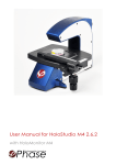
HoloMonitor M4
®
®
Setup and Operational Manual
Dec 2015, rev. 2
Phase
Holographic Imaging
This manual is issued by:
Phase Holographic Imaging PHI AB
Scheelevägen 22 | 223 63 Lund | Sweden
www.phiab.se | [email protected]
© 2015 Phase Holographic Imaging PHI AB | All rights reserved
2
Contents
1
Instrument safety
4
2
Warranty
4
3
Description
5
4
Hardware installation
6
5
Placing HoloMonitor M4 inside a cell Incubator
7
6
Installing the Hstudio software
8
7
Starting Hstudio for the first time
11
8
Focusing
12
9
Maintenance
14
10 Troubleshooting
16
Pre-experiment Quick Guide
18
How to use the manual
This manual can be used for all models of the cell analyzer HoloMonitor M4. It is partly a setup manual that will show
how to set up the instrument, connect it to a computer and install the Hstudio software, and partly a quick-start
and maintenance manual. The maintenance part describes how to clean, acclimatize, calibrate and store the HoloMonitor and also how the three different sample stages are operated to focus objects.
An on-line version of this manual is available at www.phiab.se/manual/m4setup.
For further assistance, please contact your regional representative of Phase Holographic Imaging.
See www.phiab.se for further information.
3
1 Instrument safety
HoloMonitor M4 was designed and tested in compliance with low voltage directive 2006/95/EC and electromagnetic compatibility 2004/108/EC. References to relevant harmonized standards used or references to the specification in relation to which conformity is declared are EN61010-1:2001 safety requirements for electrical equipment
for measurement and EN60825-1:2007 safety for laser products.
This operation manual includes information and warnings which must be observed by the user. It contains information notes as well as information of importance to safety of personnel and property. If the equipment is used
in a manner not specified in the manual, the protection provided by the equipment may be impaired. Information
symbols are categorized as follows:
Important information
Risk for physical damage on person or property, if the given instructions are not followed.
Risk for electrical shock that might cause damage to person or property if the given instructions are not followed.
Risk for laser light causing damage to person or property if the given instructions are not followed.
2 Warranty
The manufacturer guarantees that the instrument has no material or production defects when delivered, according to EU directive 99/44/EC sale of consumer goods and associated guarantees. If the manufacturer is informed
within 6 months after delivery, the manufacturer is obliged to rectify such defects. It is the manufacturers decision
whether to repair the instrument or replace the instrument with an instrument free of defects. No guarantee is
provided for defects caused by natural wear (wearing parts in particular) or improper use.
The instrument manufacturer is not liable for damage caused by faulty operation, negligence or any other meddling with the instrument, particularly the removal or replacement of instrument components, or the use of accessories from other manufacturers. This forfeits all the claims against warranty.
With the exception of the work specified in this manual, no maintenance or repair of HoloMonitor M4 may be
performed. Repairs may only be performed by specially authorized personnel.
4
3 Description
HoloMonitor M4 is an imaging time-lapse cytometer based on holographic microscopy, providing imaging and
quantification of unstained living cells directly in their culture vessels. It is designed to operate on the lab bench or
in a cell incubator.
HoloMonitor M4 is controlled by a computer running the proprietary Hstudio cell analysis and tracking software,
further described in the Hstudio User Manual.
Optionally, HoloMonitor M4 may be equipped with either a fixed stage, a manual operated XY stage or a software
controlled motorized XYZ stage.
3
1
2
4
5
6
10
7
8
11
9
12
INSTRUMENT PARTS, FIXED STAGE
The HoloMonitor M4 instrument contains the following parts:
1.
2.
3.
4.
5.
6.
HoloMonitor M4, with fixed sample stage
Laser unit
Optical fiber
Spacer plates
Main unit power supply
Laser unit power supply
7. USB cable
8. USB memory
9. Laser unit power adapters
10. Main unit power cord
11. Cotton swabs
12.PHI-lid fitting 35 mm Petri dish
SAMPLE REQUIREMENTS
Cells
Mono-layer of adherent eukaryotic cells in any of the recommended cell culture vessels (T25, 6-well, Petri-dishes,
IBIDI 1 or multi-channel slides). Eukaryotic suspension cells need to be mounted on a microscope slide, a Nexcelom
counting chamber or a cell culture vessel similar to IBIDI slides.
Cell culture vessels
For the best imaging quality, use 35 mm Petri dish with the PHI-lid (Appendix 1), IBIDI slides or similar. Small petri dishes
and small cell culture flasks will work. Glass-bottom Petri dishes are highly recommended. For a complete list of recommended cell culture vessels see www.phiab.se/support/vessel.
5
4 Hardware installation
Step 1 – Attaching the sample stage
1. Place the instrument on a stable table.
2. HoloMonitor M4 is normally shipped with the
stage attached.
3. If the stage is not attached, attach the stage by placing
it with the small pin on the back of the stage inserted in
the fitting hole the main unit (red circle).
4. Lock the stage in position by pulling and releasing
the locking knob (red arrow).
Step 2 – Connecting the laser unit
1. Carefully remove the protective cap from the Optical
fiber (3) tip. Save the protective cap for future use.
2. Gently insert the optical fiber tip into the fiber connector. Make sure that the sprint (yellow arrow) is
aligned to the connector socket (red arrow) before
tightening the lock ring.
3. Connect the Laser unit power supply (6) to the
Laser unit (2).
4. Connect the laser unit power supply to a power outlet using one of the Laser unit power adapters (9).
The optical fiber must be handled gently. Do not forcefully stretch or bend the fiber. Do not touch the fiber tip.
The laser needs approximately 15 seconds to warm up before the laser light is visible. An additional 15 minutes is
required before it is fully stabilized.
The HoloMonitor M4 laser is Class 2M laser. A Class 2M laser is safe because of the aversion response, if not viewed
through optical instruments. However, to avoid any unnecessary discomfort when handling the disconnected optical
fiber, make sure that the laser beam emerging from the fiber does not radiate directly into somebody’s eye.
Step 3 – Connecting the USB cable
1. Connect the USB cable (7) in the micro USB
connector (red circle).
2. Connect the USB cable to your computer.
Step 4 – Connecting power
1. Connect the Main unit power supply (5) to the
power connector (yellow circle). Make sure the
connector is in the correct position before tightening the lock ring.
2. Connect the Main unit power cord (10) to the
power supply
3. Connect the power cord to a power outlet.
6
5 Placing HoloMonitor M4 inside a cell Incubator
1. Disconnect the Laser unit power supply (6) from the power outlet.
2. Disconnect the Optical fiber (3), the USB cable (7) and the Main unit power supply (5) cable from the instrument.
3. Put on the protective cap on the optical fiber tip. Do not touch the fiber tip.
4. Place HoloMonitor M4 inside the cell incubator.
5. Pull the optical fiber, the USB cable and the power supply cable through the access port of the incubator
and reconnect them to the instrument.
6. Finally, reconnect the laser unit power supply to the power outlet.
7. After at least three hours of acclimatization, run the Calibration Wizard as described on page 14 to ensure that the instrument operates optimally before proceeding with any experiment.
Be careful when handling the optical fiber so it is not stretched, pulled, bent or harmed in any way.
To avoid build-up of internal condensation, HoloMonitor M4 must have power at all times while inside the
incubator.
7
6 Installing the Hstudio software
Step 1 – Computer requirements
Make sure the computer fulfills the minimum requirements:
Minimum
Windows 7 or later, 64-bit
1.5 GHz 64-bit
4 GB RAM
10 GB free
Operating system
Processor
Memory
Hard drive
Recommended
Windows 8.1, 64-bit
Intel Core i7
8 GB RAM
SSD, additional hard drive for user data storage
The files associated with Hstudio are stored in the folder C:\PHI, which must not be used for anything else. User created data is stored under C:\PHI as well. However, the user data location can be changed at any time.
Step 2 – Backup
If Hstudio already is installed, make a backup of all
projects and groups by exporting them. Go to
Database → Export
Step 3 – Uninstall previous version
Uninstall previous Hstudio version prior to installation.
Previously created user data will not be removed. Go to
Control Panel → Uninstall
Step 4 – Installation
Locate the installation executable file setup.exe on the
USB memory (8) and double-click it to begin installation.
8
Accept the user account control question by clicking Yes.
Step 5 – Prerequisites installation
The installation will start with prerequisites installation which
launches separate installation programs from third-party vendors.
It is possible that this step does not occur depending on the
computer configuration.
Click Install to continue and wait for the installation to complete.
Step 6 – Hstudio installation
Progression of installation.
Click Next to continue.
9
Enter your information. Click Next to continue.
Click Install to start the installation process.
Click Finish to complete the installation.
10
7 Starting Hstudio for the first time
Step 1 – Connect the instrument
Connect the fully assembled instrument to
the computer using the USB cable (7). Drivers will be installed automatically when the
USB-cable is attached and power is turned on.
Step 2 – Start Hstudio
A shortcut icon to the program is placed under
start menu All Programs → Hstudio and on the
Desktop. Use either one to start the program.
If a previous version of Hstudio was installed
prior to this installation, then a question
dialog is shown on first start-up. Select Yes
to gain access to the images obtained in the
previous version.
Step 3 – Calibration
Whenever the Live Capture tab is selected for
the first time after starting Hstudio, Hstudio will
automatically initiate a recalibration.
Select the Live Capture tab, remove any sample from the stage and click Continue to enter
the Calibration Wizard. Follow the Calibration
Procedure on page 14.
After successfully calibrating HoloMonitor M4,
select the Live Capture tab (red ellipse)
and place a cell sample on the stage.
A normal holographic image of the cell
sample should now be visible. If the image
looks light-saturated (image insert) it may
be necessary to click the “R”-button (red
arrow) to adjust the image.
For focusing instructions, see Focusing on
page 12.
For more information on how to use Hstudio,
see the Hstudio Software Manual.
11
8 Focusing
For the HoloMonitor M4 software auto focus to operate correctly, the cells needs to be positioned within the auto
focus range, approximately 1 mm above the objective lens. This is achieved differently depending on the which
sample stage HoloMonitor M4 is equipped with.
Examples of a focused and unfocused image:
When the sample is in focus the rectangular slider in
the Hstudio Software focus window will be within the
green range.
For additional instruction on focusing, see Hstudio
Software Manual.
FIXED STAGE
When using the fixed stage, one or more spacer plates
are used to vertically position the cell culture vessel
within the auto focus range. Four spacer plates with
varying thickness are provided, 1, 1.5, 2 and 2.5 mm
marked with 1 – 4 respectively. A list of which spacer
plates to use with commonly used brands and types of
cell culture vessels is available at www.phiab.se/support/vessel.
When placing a spacer plate on to the stage, make
sure that the two pins on the table are positioned in
the holes in the spacer plate.
12
MANUAL STAGE
The manual stage is delivered with vessel holders for
standard cell culture vessels. When the appropriate vessel
holder is used, the cells will be within the auto focus range.
The vessel holder is attached on to the X-arm by pushing it
down onto the holder like a jigsaw-puzzle (inset image).
MOTORIZED STAGE
HoloMonitor M4 with motorized stage is delivered
with three different vessel holders, for microscope
slides, standard multi-well plates and for standard 35
mm Ø Petri dishes.
Attachment of the vessel holder to the stage is done by
clicking it on from the side, as seen in the adjacent image.
The cells are positioned within the auto focus range by using the virtual focusing wheel in the Hstudio Microscope
settings window.
13
9 Maintenance
To obtain the best experimental results and to avoid unnecessary work-flow disturbances, start preparing the experiment two days in advance by following the instructions below. A quick guide is found at the end of this document.
For more detailed calibration instructions, see the Hstudio Software Manual.
PERIODIC CALIBRATION
HoloMonitor M4 should be re-calibrated every 10 days or if it has not been used recently.
CALIBRATION WIZARD
To start the Calibration Procedure start the
Calibration Wizard from the Help pull-down
menu in Hstudio.
CALIBRATION PROCEDURE
If Hstudio fails to perform a calibration, a
warning will appear. After verifying that
HoloMonitor M4 is installed according to
the instructions page 6 click OK and
click Recalibrate when the Calibration Wizard window appears to refresh the Diagnostics Values.
The three Diagnostic Values measure the image quality. All values should be in the green
range. If this not the case, please perform
the Cleaning Instructions on page 15.
After cleaning click Recalibrate to refresh
the Diagnostics Values.
COLLECT DIAGNOSTICS
If any of the Diagnostic Values remain outside the green range after several cleaning
attempts and over-night drying, run the
Collect Diagnosis tool, follow the instructions
and send the resulting zip-file to
[email protected]
for further assistance.
14
CLEANING INSTRUCTIONS
Step 1 – Cleaning optical surfaces
The top of the objective and the object beam
window are cleaned with a fresh Cotton swab (11)
dipped in 70% ethanol. Use a dry cotton swab to
remove ethanol residues. Repeat the cleaning if the
Diagnostic Values are not in the green range.
An instruction video of how to clean the instrument is
available at
www.phiab.se/support
Step 2 – Over-night drying
If repeated cleaning does not improve the Diagnostic Values, the problem may be due to condensation, built-up on
the optics inside the instrument. The instrument should then be removed from the incubator and placed at room
temperature over-night to dry out. After drying, run the Calibration Wizard as described page 14 to ensure that
the Diagnostic Values are within the green ranges before proceeding with to the Incubator Acclimatization.
INCUBATOR ACCLIMATIZATION
Place HoloMonitor M4 in the incubator according to Placing HoloMonitor M4 inside a cell Incubator on page 7.
After at least three hours of acclimatization, run the Calibration Wizard as described page 14 to ensure the instrument operates optimally before proceeding with any experiment.
Make sure that the power supply to HoloMonitor is always on when the instrument is inside the incubator.
LONG-TERM STORAGE
Long term storage of the HoloMonitor should be at room temperature outside the incubator. Use a dust cover if the
instrument is not in use for a longer period of time. All cords and the laser fiber can be kept inside the incubator at all
times if it is inconvenient to remove them. When detaching the laser fiber, use the protective cap of the laser fiber.
Before re-installing the HoloMonitor into the incubator, run the calibration wizard to assure clean optical surfaces.
CLEANING INSTRUMENT EXTERIOR
The instrument can be wiped down with a damp cloth (ethanol or water). Cleaning must be performed so that no liquid
enters the interior of the instrument. Use a dust cover when the instrument is not in use for a longer period of time.
15
10 Troubleshooting
THE “LIVE CAPTURE” TAB IS DISABLED
1. Check that the USB-cable is properly attached between the computer and the instrument. Try reconnecting
the USB-cable and restarting Hstudio.
2. Check Drivers.
3. Start the Windows Device Manager and check for any drivers with exclamation marks.
4. Try disconnecting the USB-cable from the instrument and connect it again and wait a couple of minutes. If the
problem persists, try to run the installation program again.
5. The driver files are located under C:\PHI\Drivers as sub folders. If a device has an exclamation mark shown in
the device manager it may be possible to re-install it by right-clicking the device and selecting Update driver.
Then browse to the driver folder under C:\PHI\Drivers and select that device.
THE INSTRUMENT DOES NOT START
1. Check that all connections are properly placed in the ports.
2. Check that the designated computer functions properly.
3. If the above does not help, contact your distributor for service.
THE INSTRUMENT STARTS, BUT THERE IS NO LIVE IMAGE
Check that the laser functions properly. A red dot that can be seen on the objective shows that the laser is running. If no red dot is visible, contact your distributor for advice or service.
16
THE IMAGE LOOKS GARBLED
•
Wrong spacer plate may be used. Make sure that the correct spacer plate is used for the cell culture vessel
to place the cells approximately 1 mm from the objective. Vessels with a thick bottom or a high socket should
be put on the thinnest spacer plate. Vessels or slides which are thin should be put on the thickest or medium
thick spacer plate. When the cells are not positioned within range of the auto focus, the image appear as in the
example images below.
•
Dirt, smudges, scratches or fingerprints on the vessel, top laser window or objective.
•
Try moving the culture vessel around to different positions. Make sure that the laser light has a free path
through the object.
•
Clean the instrument as described in Cleaning Instructions on page 15.
•
Condensation on the roof of the vessel. Keep vessels at the same temperature and humidity as the surrounding the instrument. Avoid transporting vessels immediately before starting a capture sequence. Use vessels
which are condensation free, e.g. IBIDI-micro channel slides, or the special PHI-lid for Petri dishes.
•
The image dynamic display is off range. Click the “R”-button under Coloring to reset the image dynamics display.
•
Re-calibrate according to section Maintenance on page 14.
•
Vibrations. Check that the cables connected to the M4 are slacking and not touching anything and create tension.
•
Make sure that the laser beam intensity is adequate. When auto-exposure is on (camera properties window
in the left side window), the exposure time for an image without a sample should be around 10 ms and never
more than 20 ms. If that is the case, contact the local distributor for advice.
•
Condensation has formed inside the HoloMonitor when placed inside the incubator. Remove it from the incubator and let it dry over-night according to Cleaning Instructions on page 15.
17
HoloMonitor M4
®
®
Pre-experiment Quick Guide
START
Start preparing your experiment one day in
advance to allow time for cleaning and drying
of the instrument, if needed.
CALIBRATION
CLEANING
Run the Calibration Procedure to verify that HoloMonitor operates optimally, see opposite page.
1. Clean the optical surfaces, see opposite page.
No
Calibration OK?
2. If problems persist after several cleanings, perform the Drying Procedure, see opposite page.
3. If problems persist after drying, Collect Diagnostics as described on the opposite page, otherwise go back to CALIBRATION
Yes
INCUBATOR
ACCLIMATIZATION
Is HoloMonitor in the incubator?
No
1. Place HoloMonitor in the incubator, see page 7
in the Setup and Maintenance manual.
2. Go back to CALIBRATION
Yes
EXPERIMENT
Run your experiment. Online manual is available
at www.phiab.se/manual/hstudio.
© 2015 Phase Holographic Imaging PHI AB | All rights reserved
CALIBRATION PROCEDURE
The Calibration Procedure is initiated by
starting the Calibration Wizard from help
pull-down menu in Hstudio.
If Hstudio fails to perform a calibration, a
warning will appear. After verifying that HoloMonitor M4 is installed as described on page
6 in the Setup and Maintenance manual
click OK and click Recalibrate when the Calibration Wizard window appears to refresh
the Diagnostics Values.
The three Diagnostic Values measure the image quality. All values should be in the green
range. If this not the case, please clean the
preform the Cleaning Instructions below.
After cleaning click Recalibrate to refresh
the Diagnostics Values.
CLEANING OPTICAL SURFACES
The top of the objective and the object beam window are cleaned with a fresh cotton swab dipped in
70% ethanol. Use a dry cotton swab to remove ethanol residues. Repeat the cleaning if the Diagnostic
Values are not in the green range.
An instruction video of how to clean the instrument is
available at
www.phiab.se/support
DRYING PROCEDURE
If repeated cleaning does not improve the Diagnostic Values, the problem may be due to condensation, built-up on
the optics inside the instrument. The instrument should then be removed from the incubator and placed at room
temperature over-night to dry out.
COLLECT DIAGNOSTICS
If any of the Diagnostic Values remain outside the green range after several cleaning
attempts and over-night drying, run the
Collect Diagnosis tool, follow the instructions
and send the resulting zip-file to
[email protected]
for further assistance.
© 2015 Phase Holographic Imaging PHI AB | All rights reserved