1
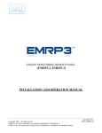
DVD Player
DVP2880/98/61/79/93/F8/05/55/40/62/X77
TABLE OF CONTENTS
Page
Location of PC Boards & Versions Variation ........................ 1
Specifications ....................................................................... 2
Safety Instruction .................................................................. 3
Software Upgrade Instruction..................................................4
Troubleshooting.................................................................... 5
Disassembly Instructions ..................................................... 6
Set Block & Wiring Diagram ................................................. 7
Circuit Diagram & PCBA Layout........................................... 8
Set Mechanical Exploded View .......................................... 9
Revision List ........................................................................ 10
Copyright 2014 WOOX Innovations Limited.
All rights reserved. No part of this publication may be reproduced, stored in a retrieval system
or transmitted, in any form or by any means, electronic, mechanical, photocopying, or otherwise
without the prior permission of WOOX Innovations. Philips and the Philips’Shield Emblem are
registered trademarks of Koninklijke Philips N.V. and are used by WOOX Innovations Limited
under license from Koninklijke Philips N.V.
Published by Arya & Lynn WK1418
Version 1.5
Subject to modification
3141 785 39425
1
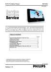
PCB BOARD LOCATION:
MAIN
BOARD
LOADER
POWER &FRONT
CONTROL BOARD
VERSION VARIATIONS
Type / Versions
Board in used
Service Policy
DVP2880
/98 /61 /79 /93 /05 /F8 /55 /40 /62 X/77
MAIN BOARD
C
C
C
C
C
C
C
C
C
C
POWER & FRONT BOARD
C
C
C
C
C
C
C
C
C
C
LOADER
M
M
M
M
M
M
M
M
M
M
*Tips:
C -- Component Lever Repair
M -- Module Lever Repair
2-1
DVP2880/98/61:
Specifications
Note
6SHFLÀFDWLRQVDUHVXEMHFWWRFKDQJHZLWKRXWQRWLFH
Region code
This player can play discs with the following
region code.
DVD region
code
Countries
$VLD3DFLÀF7DLZDQ.RUHD
Playable media
DVD, DVD-Video, VCD, SVCD, Audio CD
DVD+R/+RW, DVD-R/-RW, DVD+R/-R
DL (Dual Layer), CD-R/-RW (maximum
IROGHUVDQGÀOHV
USB storage device
File format
Video: avi, .divx, .xvid
Audio: .mp3, .wma
3LFWXUHMSJMSHJ
USB
Compatibility: Hi-Speed USB (2.0)
Class support: USB Mass Storage Class
File system: FAT16, FAT32, NTFS
Maximum number of albums/folders: 200
Maximum number of tracks/titles: 9999
USB port: 5V , 500mA
Support USB HDD (Hard Disc Drive): an
external power source may be needed
Video
Signal system: PAL, NTSC, Multi
Composite video output: 1 Vp-p (75 ohm)
HDMI output: 480i, 480p, 576i, 576p, 720p,
1080i, 1080p, Auto
Audio
2-channel analog output
Audio Front L&R : 2 Vrms (47k Ohm)
Digital output: 0.5 Vp-p (75 Ohm)
Coaxial
HDMI output
Sampling frequency:
MP3: 22.05 kHz, 24 kHz, 32 kHz, 44.1
kHz 48 kHz
WMA: 44.1 kHz, 48 kHz
Constant bit rate:
MP3: 8 kbps - 320 kbps
WMA: 64 kbps - 192 kbps
Main unit
Dimensions (W x H x D):
270 x 37.5 x 209 (mm)
Net Weight: 1.0 kg
Power
Power supply rating: 110-240V~, 50-60Hz
Power consumption: 11W
Power consumption in standby mode: <
0.5W
Accessories supplied
Remote control and one battey
AV cables
User manual
/DVHUVSHFLÀFDWLRQ
Type: Semiconductor laser InGaAIP (DVD),
AIGaAs (CD)
Wave length: 658 nm (DVD), 790 nm
(CD)
Output Power: 7.0 mW (DVD), 10.0 mW
(VCD/CD)
Beam divergence: 60 degrees
2-2
DVP2880/79:
Specifications
Note
6SHFLÀFDWLRQVDUHVXEMHFWWRFKDQJHZLWKRXWQRWLFH
This player can play discs with the following
region code.
DVD region
code
Countries
Australia, New Zealand
Playable media
DVD, DVD-Video, VCD, SVCD, Audio CD
DVD+R/+RW, DVD-R/-RW, DVD+R/-R
DL (Dual Layer), CD-R/-RW (maximum
IROGHUVDQGÀOHV
USB storage device
File format
Video: avi, .divx, .xvid
Audio: .mp3, .wma
3LFWXUHMSJMSHJ
USB
Compatibility: Hi-Speed USB (2.0)
Class support: USB Mass Storage Class
File system: FAT16, FAT32, NTFS
Maximum number of albums/folders: 200
Maximum number of tracks/titles: 9999
USB port: 5V , 500mA
Support USB HDD (Hard Disc Drive): an
external power source may be needed
Video
Signal system: PAL, NTSC, Multi
Composite video output: 1 Vp-p (75 ohm)
HDMI output: 480i, 480p, 576i, 576p, 720p,
1080i, 1080p, Auto
Audio
2-channel analog output
Audio Front L&R : 2 Vrms (47k Ohm)
Digital output: 0.5 Vp-p (75 Ohm)
Coaxial
HDMI output
Sampling frequency:
MP3: 22.05 kHz, 24 kHz, 32 kHz, 44.1
kHz 48 kHz
WMA: 44.1 kHz, 48 kHz
Constant bit rate:
MP3: 8 kbps - 320 kbps
WMA: 64 kbps - 192 kbps
Main unit
Dimensions (W x H x D):
270 x 37.5 x 209 (mm)
Net Weight: 1.0 kg
Power
Power supply rating: 230-240V~, 50Hz
Power consumption: 11W
Power consumption in standby mode:
< 0.5W
Accessories supplied
Remote control and one battery
AV cables
User manual
/DVHUVSHFLÀFDWLRQ
Type: Semiconductor laser InGaAIP (DVD),
AIGaAs (CD)
Wave length: 658 nm (DVD), 790 nm
(CD)
Output Power: 7.0 mW (DVD), 10.0 mW
(VCD/CD)
Beam divergence: 60 degrees
2-3
DVP2880/93:
Specifications
Note
6SHFLÀFDWLRQVDUHVXEMHFWWRFKDQJHZLWKRXWQRWLFH
Region code
This player can play discs with the following
region code.
DVD region code
Countries
China
Playable media
DVD, DVD-Video, VCD, SVCD, Audio CD
DVD+R/+RW, DVD-R/-RW, DVD+R/-R
DL (Dual Layer), CD-R/-RW (maximum
IROGHUVDQGÀOHV
USB storage device
File format
Video: avi, .divx, .xvid
Audio: .mp3, .wma
3LFWXUHMSJMSHJ
USB
Compatibility: Hi-Speed USB (2.0)
Class support: USB Mass Storage Class
File system: FAT16, FAT32, NTFS
Maximum number of albums/folders: 200
Maximum number of tracks/titles: 9999
USB port: 5V , 500mA
Support USB HDD (Hard Disc Drive): an
external power source may be needed
Video
Signal system: PAL, NTSC, Multi
Composite video output: 1 Vp-p (75 ohm)
HDMI output: 480i, 480p, 576i, 576p, 720p,
1080i, 1080p, Auto
Audio
2-channel analog output
Audio Front L&R : 2 Vrms (47k Ohm)
Digital output: 0.5 Vp-p (75 Ohm)
Coaxial
HDMI output
Sampling frequency:
MP3: 22.05 kHz, 24 kHz, 32 kHz,
44.1 kHz 48 kHz
WMA: 44.1 kHz, 48 kHz
Constant bit rate:
MP3: 8 kbps - 320 kbps
WMA: 64 kbps - 192 kbps
Main unit
Dimensions (W x H x D):
270 x 37.5 x 209 (mm)
Net Weight: 1.0 kg
Power
Power supply rating: 110-240V~, 50-60Hz
Power consumption: 11W
Power consumption in standby mode:
< 0.5W
Accessories supplied
Remote control and one battery
AV cables
User manual
/DVHUVSHFLÀFDWLRQ
Type: Semiconductor laser InGaAIP (DVD),
AIGaAs (CD)
Wave length: 658 nm (DVD), 790 nm
(CD)
Output Power: 7.0 mW (DVD), 10.0 mW
(VCD/CD)
Beam divergence: 60 degrees
2-4
DVP2880/05/40/62:
Specifications
Note
6SHFLÀFDWLRQVDUHVXEMHFWWRFKDQJHZLWKRXWQRWLFH
Region code
This player can play discs with the following
region codes.
DVD region code
Countries
Europe
Playable media
DVD, DVD-Video, VCD, SVCD, Audio CD
DVD+R/+RW, DVD-R/-RW, DVD+R/-R
DL (Dual Layer), CD-R/-RW (maximum
IROGHUVDQGÀOHV
USB storage device
File format
Video: avi, .divx, .xvid
Audio: .mp3, .wma
3LFWXUHMSJMSHJ
USB
Compatibility: Hi-Speed USB (2.0)
Class support: USB Mass Storage Class
File system: FAT16, FAT32, NTFS
Maximum number of albums/folders: 299
Maximum number of tracks/titles: 648
USB port: 5V , 500mA
Support USB HDD (Hard Disc Drive): an
external power source may be needed
Video
Signal system: PAL, NTSC, Multi
Composite video output: 1 Vp-p (75 ohm)
HDMI output: 480i, 480p, 576i, 576p, 720p,
1080i, 1080p, Auto
Audio
2-channel analog output
Audio Front L&R : 2 Vrms (47k Ohm)
Digital output: 0.5 Vp-p (75 Ohm)
Coaxial
HDMI output
Sampling frequency:
MP3: 22.05 kHz, 24 kHz, 32 kHz, 44.1
kHz 48 kHz
WMA: 44.1 kHz, 48 kHz
Constant bit rate:
MP3: 8 kbps - 320 kbps
WMA: 64 kbps - 192 kbps
Main unit
Dimensions (W x H x D):
270 x 37.5 x 209 (mm)
Net Weight: 1.0 kg
Power
Power supply rating: 220-240V~, 50-60Hz
Power consumption: 11W
Power consumption in standby mode:
< 0.5W
Accessories supplied
Remote control and one battery
User manual
/DVHUVSHFLÀFDWLRQ
Type: Semiconductor laser InGaAIP (DVD),
AIGaAs (CD)
Wave length: 658 nm (DVD), 790 nm
(CD)
Output Power: 7.0 mW (DVD), 10.0 mW
(VCD/CD)
Beam divergence: 60 degrees
2-5
DVP2880/F8:
Specifications
Note
6SHFLÀFDWLRQVDUHVXEMHFWWRFKDQJHZLWKRXWQRWLFH
Region code
This player can play discs with the following
region code.
DVD region code
Countries
Latin
America
Playable media
DVD, DVD-Video, VCD, SVCD, Audio CD
DVD+R/+RW, DVD-R/-RW, DVD+R/-R
DL (Dual Layer), CD-R/-RW (maximum
IROGHUVDQGÀOHV
File format
Video: MPEG 1, MPEG 2
3LFWXUHMSJMSHJ
Video
Signal system: PAL, NTSC, Multi
Composite video output: 1 Vp-p (75 ohm)
HDMI output: 480i, 480p, 576i, 576p, 720p,
1080i, 1080p, Auto
Audio
2-channel analog output
Audio Front L&R : 2 Vrms (47k Ohm)
Digital output: 0.5 Vp-p (75 Ohm)
Coaxial
HDMI output
Main unit
Dimensions (W x H x D): 270 x 37.5 x
209 (mm)
Net Weight: 1.0 kg
Power
Power supply rating: 110-127V~, 60Hz
Power consumption: 11W
Power consumption in standby mode:
< 0.5W
Accessories supplied
Remote control and one battery
User Manual
/DVHUVSHFLÀFDWLRQ
Type: Semiconductor laser InGaAIP (DVD),
AIGaAs (CD)
Wave length: 658 nm (DVD), 790 nm
(CD)
Output Power: 7.0 mW (DVD), 10.0 mW
(VCD/CD)
Beam divergence: 60 degrees
2-6
DVP2880/55:
Specifications
Note
6SHFLÀFDWLRQVDUHVXEMHFWWRFKDQJHZLWKRXWQRWLFH
Region code
This player can play discs with the following
region code.
DVD region code
Countries
Latin America
Playable media
DVD, DVD-Video, VCD, SVCD, Audio CD
DVD+R/+RW, DVD-R/-RW, DVD+R/-R
DL (Dual Layer), CD-R/-RW (maximum
IROGHUVDQGÀOHV
USB storage device
File format
Video: avi, .divx, .xvid
Audio: .mp3, .wma
3LFWXUHMSJMSHJ
USB
Compatibility: Hi-Speed USB (2.0)
Class support: USB Mass Storage Class
File system: FAT16, FAT32, NTFS
Maximum number of albums/folders: 200
Maximum number of tracks/titles: 9999
USB port: 5V , 500mA
Support USB HDD (Hard Disc Drive): an
external power source may be needed
Video
Signal system: PAL, NTSC, Multi
Composite video output: 1 Vp-p (75 ohm)
HDMI output: 480i, 480p, 576i, 576p, 720p,
1080i, 1080p, Auto
Audio
2-channel analog output
Audio Front L&R : 2 Vrms (47k Ohm)
Digital output: 0.5 Vp-p (75 Ohm)
Coaxial
HDMI output
Sampling frequency:
MP3: 22.05 kHz, 24 kHz, 32 kHz, 44.1
kHz 48 kHz
WMA: 44.1 kHz, 48 kHz
Constant bit rate:
MP3: 8 kbps - 320 kbps
WMA: 64 kbps - 192 kbps
Main unit
Dimensions (W x H x D):
270 x 37.5 x 209 (mm)
Net Weight: 1.0 kg
Power
Power supply rating: 110-240V~, 50-60Hz
Power consumption: 11W
Power consumption in standby mode:
< 0.5W
Accessories supplied
Remote control and one battery
AV cables
AC power plug adapter
User manual
/DVHUVSHFLÀFDWLRQ
Type: Semiconductor laser InGaAIP (DVD),
AIGaAs (CD)
Wave length: 658 nm (DVD), 790 nm
(CD)
Output Power: 7.0 mW (DVD), 10.0 mW
(VCD/CD)
Beam divergence: 60 degrees
3-1
Safety instruction, Warning & Notes
Safety instruction
1. General safety
2.Laser safety
Safety regulations require that during a repair:
. Connect the unit to the mains via an isolation transformer.
. Replace safety components indicated by the symbol
,
only by components identical to the original ones. Any
other component substitution (other than original type)
may increase risk of fire or electrical shock hazard.
Safety regulations require that after a repair, you must
return the unit in its original condition. Pay, in particular,
attention to the following points:
. Route the wires/cables correctly, and fix them with the
mounted cable clamps.
. Check the insulation of the mains lead for external
damage.
. Check the electrical DC resistance between the mains
plug and the secondary side:
1) Unplug the mains cord, and connect a wire between
the two pins of the mains plug.
2) Set the mains switch the “on” position (keep the
mains cord unplug).
3)
Measure the resistance value between the mains
plug and the front panel, controls, and chassis
bottom.
4)
Repair
or
correct
unit
when
¡
measurement is less than 1M
the
resistance
.
5) Verify this, before you return the unit to the
customer/user (ref. UL-standard no. 1492).
6) Switch the unit “off”, and remove the wire between
the two pins of the mains plug.
This unit employs a laser. Only qualified service personnel
may remove the cover, or attempt to service this device
(due to possible eye injury).
Laser device unit
Type
: Semiconductor laser GaAlAs
Wavelength
: 650nm (DVD)
: 780nm (VCD/CD)
Output power
: 7mW (DVD)
: 10mW (DVD /CD)
Beam divergence: 60 degree
Note: Use of controls or adjustments or performance of
procedure other than those specified herein, may result in
hazardous radiation exposure. Avoid direct exposure to
beam.
3-2
6HUYLFH+LQWV
&$87,21
&+$5*('&$3$&,7256217+(6(592%2$5'0$<'$0$*(7+('5,9(
(/(&7521,&6:+(1&211(&7,1*$1(:'5,9(7+$7¶6:+<%(6,'(67+(6$)(7<
0($685(6/,.(
6:,7&+2))32:(56833/<
(6'3527(&7,21
$'',7,21$/$&7,2160867%(7$.(1%<7+(5(3$,57(&+1,&,$1
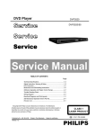
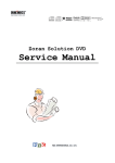
7KHIROORZLQJVWHSVKDYHWREHGRQHZKHQUHSODFLQJWKHGHIHFWLYHORDGHU
'LVPDQWOLQJRIWKHORDGHUWRDFFHVVWKH(6'SURWHFWLRQSRLQWLIQHFHVVDU\
6ROGHUWKH(6'SURWHFWLRQSRLQW 'LVFRQQHFWÀH[IRLOFDEOHIURPWKHGHIHFWLYHORDGHU
3XWDSDSHUFOLSRQWKHÀH[IRLOWRVKRUWFLUFXLWWKHFRQWDFWV¿J
5HSODFHWKHGHIHFWLYHORDGHUZLWKDQHZORDGHU
5HPRYHSDSHUFOLSIURPWKHÀH[IRLODQGFRQQHFWLWWRWKHQHZORDGHU
5HPRYHVROGHUMRLQWRQWKH(6'SURWHFWLRQSRLQW
$77(17,217KHODVHUGLRGHRIWKLVORDGHULVSURWHFWHGDJDLQVW(6'E\DVROGHUMRLQWZKLFKVKRUWFLUFXLWVWKHODVHUGLRGHWRJURXQG
)RUSURSHUIXQFWLRQDOLW\RIWKHORDGHUWKLVVROGHUMRLQWPXVWEHUHPRYHDIWHUFRQQHFWLRQORDGHUWRWKHVHW
Solder Joint
(6'SURWHFWLRQSRLQWLVDFFHVVLEOHIURPWRSRIORDGHU
2QO\DSSOLFDEOHIRUGHIHFWLYHORDGHUQHHGHGWREHVHQWEDFNWRVXSSOLHUIRUIDLOXUHDQDO\VLVDQGWRVXSSRUWEDFNFKDUJLQJ
HYLGHQFH
7KLVLVDOVRDSSOLFDEOHIRUDOOSDUWQHUVKLSZRUNVKRSV
4
Software upgrade
Preparation to upgrade software
1)
Start the CD Burning software and create a new CD project (Data Disc) with the following setting:
Label: DVP3XXX (No need the label name)
File Name: DVPXXXX_XX.BIN
Power on the set and open the tray, then press <option> to check the File Name.
Note: It is required capital letter for the File System name
2)
Burn the data onto a blank CDR
A.
Procedure for software upgrade:
1)
Power on the set and insert the prepared Upgrade CDR.
2)
The set will starts reading disc & response with the following display TV screen:
Upgrade file detected
VXX(SW VER )
<X>
3)
<O>
Press <OK> button to confirm, then screen will display :
Upgrade file detected
UPGRADING…
Do not power off…
4)
The upgraded tray will automatically open when files coping complete, then take out the disc.
5)
About 1 minute later, the trace will automatically close when upgrading complete.
B.
Read out the software versions to confirm upgrading
1)
Power on the set and press <Setup> button on the remote control.
2)
Press <Up><Next>< Up >< Up ><OK> button.
The software version and other information are display on the TV screen as follows:
Model
DVP3XXX_ XX
File Name
DVPXXXX_XX.BIN
Version
XX.XX.XX.XX
8203RX
XX.XX.XX.XX
RISC
XXXXXX-XXX-XXX
Servo
XXXXX-XXX-XXXX
Region Code
X
Caution: The set must not be power off during
upgrading, Otherwise the Main board will be
damaged entirely. 5-1
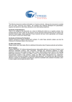
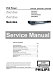
Trouble shooting chart
Spindle motor does not move
Motor no move
Go
Check
the
FFC
No
connection between
Correct connection
24PIN and the loader.
Yes
Check whether “M5V”
No
Check the M5V power supply
(+5V) voltage is normal.
Yes
1.Whether the R12 is eroded or
badly soldered.
2.Whether peripheral components
between U1 and xp5 are eroded
or badly soldered.
Yes
Check/ Replace U1
No
Check/Replace the loader,or the bad part.
Trouble shooting chart
5-2
The power can not be on or off
The power can’t be
on or off
Go
Check the power supply
No
on the power board is
Repair the power board
normal.
Yes
Check if the XS2 on the
front board to XP1 on
the
Yes
No
Check/Correct connection
decoder board is in good
contact.
Yes
Whether the connection
No
to K303 is broken.
Correct the connection
Yes
Whether there is 0V and
3.3V voltage difference on
Pin 10 LED/PCON of U1.
Yes
No
Replace U1.
5-3
All output voltages on the power board is 0V or deviated.
Trouble shooting chart
All output voltages on
the power board is 0V or
deviated
Yes
Check whether
Yes
Replace F501
F501 is blown
No
Check whether there is
No
Replace C501&C502 if D501, D502,
D503, D504 are normal.
300V on C501 or C502.
Yes
Check whether 100KHz
oscillating signal on
Pin4 of U501
No
Check/ replace U501.
U501(PIN 4 - Drain waveform)
Yes
Check if +5V
short.
Yes
Check whether the components in the
short-circuit voltage are defected or eroded.
No
Check whether U501 are eroded.
Trouble shooting chart
5-4
Disc cannot be read.
Disc cannot be read.
Yes
No
Check the FFC connection
Check the loaded circuit
between 24P and the loader.
Yes
Check whether the current of
R12 is Less than 60mA for
DVD and 65mA for CD.
No
Replace the Loader
Yes
Check
whether
the
components
between of
U1 ,and xp3 are eroded or
defect
No
Replace the defective parts
Yes
Check if there is RFO signal on
pin17 of XP3. (The normal RFO
signal is a clear reticulated wave)
No
Check U1 and peripheral components
Yes
Check the connection
between U1
Yes
Replace U1
No
Correct connection
5-5
Only DVD disc or only disc except DVD can be played
Only DVD disc, or only disc
except DVD can be Played.
Go
Check
the
FFC
connection between
24pin and the loader.
No
Check the loaded circuit
Yes
Check whether the current
of R12 is Less than 60mA
for DVD and 65mA for
CD.
No
Replace loader
Yes
Check whether the components
between
U1 and xp3 are
eroded or defect
No
Replace the bad spare parts
Yes
Check
whether
the
connection of xp5 are
eroded or defect
Yes
Change U1
No
Replace the bad xp3
Trouble shooting chart
Trouble shooting chart
5-6
No display on LED, and buttons do not work
No display on LED, and
buttons do not work
Yes
Check whether there is
correct
contact
between XS2 and XP1
No
Correct connection
Yes
Check
VCC(M5V)
voltage on the power
and front board
Fix power supply board top
a power supply for should
electric circuit
No
Yes
Check there are STB,
SDA and SCK signals on
XS2 on the front board.
No
Check the U1’s pin 17,18,19 arrive
the XP1 connect condition
XP6 (PIN 2 CLK)
XP6 (PIN4 DOUT)
Yes
1.Check whether bad solder exists on
U301 and pins of LED,
2.Check whether the circuit connected
to K302, K303 and K301 is broken,
3.Check whether R303, R304,R305 on
front board are open-circuit.
Yes
Replace U301 or LED
No
Correct connection
Trouble shooting chart
5-7
Distorted audio and loud noise
Distorted audio and
loud noise
Yes
Check the power supply
voltages
+5V
to
the
operation amplifying Q1 is
normal.
No
Check Q1
Yes
Check
whether
the
muting resistance R133
is normal
No
Replace R133
Yes
Check whether the muting
resistance R132 is normal
No
Replace R132
Yes
Checking the U927
leads the feet has no to
break to open
No
Correct connection
Yes
Check the voltage on
pin7 of U927 is OK.
No
Replace R134
Yes
Check whether the U1
or U927 power supply
normal
Yes
Replace U1 or U927
No
Check U927
Trouble shooting chart
5-8
Abnormal color of video picture
Abnormal color of
video picture
Yes
Check whether the 27MHz
No
Check X3, R79,R6 ,C26 and C27
output signal normal.
Yes
Check whether the 3.3V
and 1.2V power supply
voltages on the decoder
board are normal.
No
Check other of power supply electric
circuit
Yes
Check whether the
video filter network
circuit is normal.
No
Correct the connection
Yes
Check if the video signals on Pin
76/78/79/80 of U1 are normal
No
change U1
Trouble shooting chart
5-9
Remote reception is insensitive or fails.
Remote reception is
insensitive or fails.
Go
Check if the remote
control works properly.
No
Check battery
Yes
Check if the power
supply voltage to the
remote censor is normal
No
Check R96、C93
Yes
Use an oscilloscope to check if
there is output waveform from the
first pin IR of the remote censor
after pressing button on the remote
control.
No
REM301(PIN1 - RC waveform)
Yes
Check if there is IR
signal on pin 16 of U1
Yes
Change U1
IR waveform
No
Correct connection
Trouble shooting chart
5-10
No video picture, no sound.
No video picture,
no sound.
Check the cable if that is
used to connect TV and
DVD Player, is normal
No
Replace the cable
Yes
Check whether all the voltages
from the power board to the
decoder board are normal.
No
Check the power board
Yes
Check if the reset circuit consisting
ofC65 normal (at a low level for
tens
of
milliseconds,
then
constantly at 3.3V).
No
Change C65,R20,U1
Yes
Crystal oscillator X3 and
Check if there is 27MHz
signal output in
No
peripheral components
are defected or eroded.
Yes
Check if the component of
vidio
output circuit.
Yes
Check U1 and Replace U1
No
Change the bad component
6-1
Mechanical and Dismantling Instructions
Dismantling Instruction
Detailed information please refer to the model set.
The following guidelines show how to dismantle the player.
Step1: Remove 5 screws around the Top Cover, and then remove the Top Cover (Figure 1).
Figure 1
Step2: If it is necessary to dismantle Loader or Front Panel, the Front door should be removed first. (Figure 2)
Note: Make sure to operate gently otherwise the guider would be damaged.
Please kindly note that dismantle
the front door
assembly carefully to avoid damage tray and the front door.
Figure 2
6-2
Mechanical and Dismantling Instructions
Dismantling Instruction
Detailed information please refer to the model set.
Step3: If the tray can’t open in normal way, you can make it through the instruction as below (Figure 3).
Note: Make sure to operate gently otherwise the guider would be damaged.
Figure 3
Step4: Dismantling Front Panel, need release 2 snaps of Front Panel & 2 snaps of bottom cabinet , then gently pull the Panel
out from the set. (Figure 4)
Figure 4
6-3
Mechanical and Dismantling Instructions
Dismantling Instruction
Detailed information please refer to the model set.
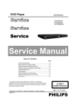
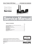
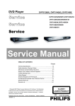
Step5: Dismantling Loader, disconnect the 3 connectors (XP5, XP8, XP9) aiming in the below figure, and remove 1 screw that
connects the loader and the bottom cabinet. (Figure 5)
Step6: Dismantling Power & Front Control Board, remove 3 screws on the board. (Figure 5)
Step7: Dismantling Main Board.Remove 1 screw on the board. (Figure 5)
XP3
XP5
XP9
XP8
Figure 5
7-1
7-1
Wiring and Block Diagram for DVP2880:
HDMI
P4
24
COAXIAL
L
CVBS
XP3
P6
AUDIO
AMP&LPF
VIDEO
LPF&DRIVER
1
U1
1
U2
XP4
SPSP+
GND
HOME
SLEDSLED+
MOTOR
DRIVER
U3
16M
FLASH
SPHE8203R
AM5890S
6
64M
SDRAM
1
2
MAIN BOARD
XP1
1
14
USB_DP
USB_DM
GND
VCC_USB
GND
IR
Power_kO
DATA
CLK
STB
+5V
MIC
+12V
GND
GND
TRIN
XP5
DVD LOADER
R
14
XS135
KEY&LED BOARD
1
USB
KOK
POWER
SUPPLY
8-1
8-1
USB Board Circuit Diagram:
5
4
3
2
1
D
D
USB INTERFACE CIRCUIT
USB
5
Shell B Shell A
6
C
TP6
TP1
P3
USB-A/BK
GND
DP
DM
VCC
4
3
2
1
TP2
FGND
USB_DP
USB_DM
USB5V
TP3
TP4
TP5
MGND
C
B
B
A
A
5
4
3
2
1
8-2
8-2
Power & Front Control Board Circuit Diagram:Power Supply
5
4
3
2
1
* CAUTION :
THE PARTS MARKED WITH
ARE IMPORTANT PARTS ON THE SAFETY.
PLEASE USE THE PARTS HAVING THE DESIGNATED PARTS NUMBER WITHOUT FAIL.
D
D
L501
HV:
HV1
HV2
680uH/300mA
GND:
F501
10 ohm2W
D501
AC INPUT
GND2
FB501
FB80@100MHz
݅⬉ᛳݐᆍϸϾ఼ӊ
1N4007/1A/1000V
HV1
1N4007/1A/1000V
2PIN/7.92mm
1
2
GND1
D502
1
2
D503
HV2
D504
C501
+
CN501
1N4007/1A/1000V
1N4007/1A/1000V
C502
+
10uF/400V
15uF/400V
20mH
LIF503
GND1
GND2
7
C
C
T501
1500pF/1KV
6
C504
R502
150K
R503
150K
GND_POWER
+5V
4
D507
GND_POWER
+5V
8
1N4007/1A/1000V
R515
10
D508
L502
D509
NC ZD502 C513
C509
+
2
FR104/1A/400V
10K
+ C512
NC/10uF/50V
0.1uF/50V/X7R
SR360/3A/60V
6.8uH/2.4A
11
+ C508
10uF/50V
+ C507
1
9
470uF/16V
1500uF/16V
R505
12K/1%
1
ZD501
100
R510
2
3
S
S
S
R508
1K
U502
PS2561L1
C511
B
3
8
7
5
B
6
S
BZX79C9V1
U501
TNY176DG
R509
BCK-2838
1
EN/UV
680
R513
100K
4
3
2
BP/M
NC
Drain
4
R506
10K
0.1uF/50V/X7R
U503
1
H431
2
R507
11.3K/1%
CY501
1000pF/250VAC
A
A
5
4
3
2
1
8-3
8-3
Power Board Circuit Diagram:FRONT & USB
5
4
3
2
1
)5200$,1%2$5'
+5V
D
D
R329 R326
R314
4.7K
2K
+5V
2 +5V
4.7k
GND
2 GND_POWER
CS
CLK
Power_KO
K1
POWER
K2
XS2
14PIN/2.0mm
1
2
3
4
5
6
7
8
9
10
11
12
13
14
1
2
3
4
5
6
7
8
9
10
11
12
13
14
C309
C310
0.1u
0.1u
PLAYER/PAUSE
GND
K3
+5V
CS
CLK
OPEN/CLOSE
Power_KO
IR
GND
USB5V
FGND
USB_DP
USB_DM
LED1
standby
C26
C25
1.7MA
5.6pF/50V/NPO/NC
5.6pF/50V/NPO/NC
C
RED
R320
LED_CS:
H: Standby
L: ON
A
2.2K/NC
CS
R319
Q2
BT3904
4.7K
C
R325
2.2K
C305
0.1uF/16V/Y5V
USB
USB5V
USB_DM
USB_DP
ESD2
VCC
GND
IR
B
IR1
C202
0.1uF/50V/Y5V
+5V
REM1
3
2
1
R318
ESD1
470
IR
LVE16Y1R0
LVE16Y1R0
B
C306
C315
47pF/50V/NP0
1uF/50V/Y5V
A
R1
FGND
0/NC
GND_POWER
A
A
5
4
3
2
1
8-4
8-4
Main Board Circuit Diagram:POWER
A
B
C
D
E
TP9
M5V
TO POWER BOARD
1
1
Q1
Imax=1000mA
M5V
M5V
RFA5V
8550D
+12V: +12V(+-10%)
C1
1uF
C5
VVCC3
0.1uF/NC
R6
+5V: +5V(+-2.5%)
P+5V
AVCC3
4.7K
R3
3.3K
USB_VCC
AD_VCC3
USB_PCON
USB_PCON
TP10
7
SPI_VCC3
DVCC3
R5
Q2
4
LED/PCON
PLLVCC3
BT3904
1K
VCC1.2
R4
HAVCC
4.7K
RF3.3V
VCC3
VCC5
A+5V
P+5V
2
RFA5V
5V for peripherals
VCC5
M5V
M5V
Power Bead > 2A, RAC@100 MHz
= 70 ohm, RDC(max)= 0.4 ohm
A+5V
P+5V
C6
0.1uF
R39
REG01
VVCC3
AVCC3
USB_VCC
AD_VCC3
SPI_VCC3
DVCC3
PLLVCC3
VCC1.2
HAVCC
RF3.3V
VCC3
VCC5
A+5V
P+5V
2
RFA5V
M5V
VCC1.2
2.2
GND
GND
RFGND
GND
HGND
M5V
R147
3
3
1.8/2W
TP7
TR_B3
TR_B3
R10
5.6/1W
3.3V for 8203R and peripherals
4 Q4
2SS8550D(EBC,1.5A,1W)
TR_B1
VCC3
TR_B1
1.2V for core of 8203r
Q5
4
2SS8550D(EBC,1.5A,1W)
TP8
DVCC3
R11
EC3
20K/1%
REG03
REG03
4
100uF/16V
RF3.3V
C8
0.1uF R40
TP32
Servo
OR
R38
close to
8203R
R12
C10
0.1uF
12K/1%
RFGND
close to
8203R
Video
ADC
GND
R16
Audio
2.2R
EC12
100uF/16V
GND
C12
0.1uF
C15
0.1uF
HGND
PLL
GND
TP12
4
HDMI
C11
0.1uF
C19
0.1uF
AVCC3
REG01
C14
0.1uF
PLLVCC3
C18
EC10
100uF/16V 0.1uF
4
REG01
0 ohm/FB500
TP13
AD_VCC3
VVCC3
OR
EC8
100uF/16V
C9
0.1uF
NC/100uF/16V
TP11
R41
L5
EC5
GND
GND
Digital
USB
2.2
GND
HAVCC
VCC1.2
USB_VCC
4
GND
SPI_VCC3
SPI Flash
close to
8203R
C21
0.1uF
GND
A
B
C
D
E
8-5
8-5
Main Board Circuit Diagram:SPHE8203R
A
B
C
D
E
TP111
TP93
place components near to 8203R
close to XP3
TP109
U1
RFGND
E
100
100
CDVR
DVDVR
F
E
XOPVIP
XOPVIN
RFGND
PUH_DVDLD
TP113
X3
CLKOUT
27
28
C133
C38
0.1uF 102
C134
102
1
2
RFGND
GND
PLLVCC3
4.7K
C104
15pF
CONTACTRFGND RFGND
C40
33pF
C41
33pF
RF3.3V
RFGND
GND
TP96 TP97 USB_VCC
DVCC3
VCC1.2
GND
GND
RF3.3V
2
RF3.3V
CLKIN
27MHz
R21
RFGND
ELCO-CON24(Left)
BOTTOM
R115
33
C42
C43
680pF
1000pF
TCO
FCO
R23
R24
91K
20K
VREF1
CLKIN
CLKOUT
USB_DM
USB_DP
VREF2
DA_TEO
DA_FEO
CDF
CDE
OPVIP
OPVIN
RF_APC_AVSS
CDMDI
DVDMDI
CDLDO
DVDLDO
SRV_AVDD
V21
DA_AVSS
PLL_VSS
PLL_VDD
CLKIN
CLKOUT
USB_AVSS
USB_DM
USB_DP
USB_AVDD
VDD_33
VDD_12
GND
V165
DA_TEO
DA_FEO
33M
R25
5.1
EC16
C45
0.1uF
TP94
47uF/16V
EC17
put these components close to 8203R
TP95
47uF/16V
Q7
DVDLDO
RFGND
2SB1132(R type)
PUH_CDLD
2SB1132(R type)
PUH_DVDLD
M+5V
R27
91K
VREF2DC
C108
0.1uF
0.1uF C50 SPDCO 2.2K
SCO
2.2K
0.1uF C51
VCC3
M5V
GND
GND
AVCC3
HGND
HGND
HGND
HAVCC
TXC+
TXC-
SPHE8203R-128
R29 SPDC_OUT
R30 SC_OUT
DMEA
DVDVR
CDVR
TRAYOUT
TRAYIN
TRAY+
Power_k
LED/PCON
USB_POWER
SPI_CE
SPI_D0
SPI_CLKIN
SPI_D1
IR_IN
VFD_CLK
VFD_STB
VFD_DATA
CDLDO
AD_AVDD
TV_AVSS
TV_DAC3
TV_DAC2
TV_DAC1
TV_AVDD
TV_AVSS
TV_AVDD
TV_DAC0
V_FSADJ
V_COMP
VDD_33
VDD_12
SPDIF_OUT
SPDIF_IN
A_MUTE/GPIO
DDC_SCL
DDC_SDA
HDMI_CEC/GPIO
HDMI_HPD/GPIO
I2S_XCLK
I2S_BCLK
I2S_LRCLK
I2S_DATA_IN
GPIO/TX2
VSS
64
63
62
61
60
59
58
57
56
55
54
53
52
51
50
49
48
47
46
45
44
43
42
41
40
39
AD_VCC3
GND
R28
470 VREF2
TP98
C47
C48
0.1uF
1uF
close to 8203R
200K max
R31
0
TP99
C31
C32
C33
0.1uF
0.1uF
C34
0.1uF
1
C35
0.1uF
GND
RFGND
VVCC3
C26
EC21 DVCC3
10uF/16V
DVCC3
VCC1.2
SPDIF_OUT
0.01uF
R22
27K
AUDIO_MUTE
DDC_SCL
DDC_SDA
HDMI_CEC
HDMI_HPD
GND
D5
1N4148
SPI_VCC3
U3
SPI_CE
SPI_D0
SPI_WP
C59
NC/0.1uF
GND
GND
1
2
3
4
CE_B
VDD
DQ0 HOLD#
WP#
SCK
GND
DQ1
8
7
6
5
SPI_HOLD
SPI_CLK
SPI_D1
SPI FLASH-DIP8
C66
C54
0.1uF
2
10pF/NC
GND
GND
SPI_WP
10K
SPI_HOLD
10K
SPI_CE
10K
NC/10K
R42
R43
R67
R101
SPI_VCC3
GND
Power_k
Place near 8203R
RFGND
RFGND
0.1uF 0.1uF
GND
TV_DAC0
V_FSADJ
V_COMP
1
2
3
4
5
6
7
8
9
10
11
12
13
14
15
16
17
18
19
20
21
22
23
24
25
26
27
28
29
30
31
32
33
34
35
36
37
38
Q6
R26
5.1
C30
0.1uF
GND
DVCC3
PUH_DVDLD#
CDMDI
DVDMDI
CDLDO
DVDLDO
103
104
105
106
107
108
109
110
111
112
113
114
115
116
117
118
119
120
121
122
123
124
125
126
127
128
C29
RX2
TX2
R19
R20
PUH_CDLD
TP112
RESET_B
CDVR#
TP110
DVDVR#
PUH_CDLD#
DVDMDI
CDMDI
GND
GND
0.1uF
0.1uF
VCC1.2
DVCC3
C36
C37
C23
USB_POWER
SPI_CLK
VREF1
EC14
DAC_VREF
RFGND
B
A
D
C
C24
C25
RFGND
LDSW
GND
10uF/16V 0.1uF
R18 5.1K
AOUT_FL
AOUT_FR
R17
10K
HAVCC
0.1uF
TX0+
TX0-
C28
VCC1.2
102
101
100
99
98
97
96
95
94
93
92
91
90
89
88
87
86
85
84
83
82
81
80
79
78
77
76
75
74
73
72
71
70
69
68
67
66
65
TP104
TP108
C109
0.1uF
RF3.3V
HGND
C27
0.1uF
C39
0.1uF
TX1+
TX1-
TP101
TP102
SPDC_OUT
SC_OUT
DMEA
DVDVR/GPIO/STEP_OUT
CDVR/GPIO/SC1_OUT
TRAYOUT/GPIO/DFCT
TRAYIN/GPIO/FGIN
TRAY+/GPIO/TRAY_OUT
Home/GPIO11
GPIO12
GPIO13
SPI_CE
SPI_D0
SPI_CLK
SPI_D1
IR/GPIO
VFD_CLK/GPIO
VFD_STB/GPIO
VFD_DAT/GPIO
VDD_12
VDD_33
RESET_B
VSS
HSYNC(1)/RX(1)/GPIO
VSYNC(1)/TX(1)/GPIO
SD_CLK/GPIO
SD_CMD/GPIO
SD_D0/GPIO
SD_D1/GPIO
SD_D2/GPIO
SD_D3/GPIO
CARD_SENSE/GPIO
CARD_RST/GPIO
GAME_D1/I2S_D2
GAME_D0/I2S_D1
GAME_LATCH/I2S_D0
GAME_CLK/RX2
VDD_33
XP3
FOCFOC+
RAD+
RADC
D
LDSW
PUHRF
A
B
F
DVCC3
DAC_VREF
DVDB
DVDA
DVDD
DVDC
RFIS
AGCCAP
AD_AVDD
AD_AVSS
LDSW
HOME/GPIO
AD_AVDD
HPGND
TX2+
TX2HAVCC
TX1+
TX1HAGND
TX0+
TX0HAVCC
TXC+
TXCHAGND
EXT_SWING
AOUT_L
AOUT_R
ADAC_AVSS
ADAC_AVDD
ADAC_AVDD
VREF
AOUT_CENTER
AOUT_SUB
ADAC_AVSS
AOUT_LS
AOUT_RS
AD_AVSS
AIN_R
24
23
22
21
20
19
18
17
16
15
14
13
12
11
10
9
8
7
6
5
4
3
2
1
TX2+
TX2-
A+5V
1
RF3.3V
RFGND
RF3.3V
LDSW
HOME
A+5V
26
25
A+5V
1uF PUHRF
0.1uF
RFGND
RFGND
TV_DAC0
V_FSADJ
IR_IN
VFD_CLK
VFD_STB
VFD_DATA
AOUT_FR
AOUT_FL
DVCC3
3
Power_k
7
USB_POWER
7
TV_DAC0
V_FSADJ
5
5
IR_IN
VFD_CLK
VFD_STB
VFD_DATA
AOUT_FR
AOUT_FL
7
7
7
7
6
6
SPDIF_OUT
AUDIO_MUTE
USB_DM
USB_DP
TR_B1
TR_B3
REG01
REG03
LED/PCON
DDC_SCL
DDC_SDA
TXC+
TXCTX0+
TX0TX1+
TX1TX2+
TX2HDMI_HPD
HDMI_CEC
6
6
7
7
3
3
3
3
3
7
7
7
7
7
7
7
7
7
7
7
7
M5V
RF3.3V
VCC3
A+5V
VVCC3
AVCC3
USB_VCC
AD_VCC3
SPI_VCC3
DVCC3
PLLVCC3
VCC1.2
HAVCC
M5V
RF3.3V
VCC3
A+5V
VVCC3
AVCC3
USB_VCC
AD_VCC3
SPI_VCC3
DVCC3
PLLVCC3
VCC1.2
HAVCC
3
TP100
R36
27K
TP14
RESET_A
R125
1K
RESET_B
C58
C57
2.2uF
0.1uF
U2
1
2
3
4
5
6
7
FCO
TR_B1
REG03
SPDCO
REG01
TRAY+
TRAY-
30
RFGND
TRAYOUT
R45
SP+
R37
XOPVIP
XOPVIN
M+5V
10K
8
9
10
11
12
13
14
LOADLOAD+
SP-
1
FOCFOC+
VINFC
CFCerr1
CFCerr2
VINSP
VNFFC
FWD
REV
GND2
Vcc1
VOLDVOLD+
VOSPVOSP+
VOFCVOFC+
STBY
BIAS
VINTK
CTKerr1
RESET
VINSL
PreGND
GND1
VCTL
VCCD
Vcc2
VOSLVOSL+
VOTKVOTK+
AM5890S
28
27
26
25
24
23
22
DMEA
VREF2DC
TCO
TR_B3
RESET_A
SCO
29
21
20
19
18
17
16
15
TP28TP26TP27TP29
M+5V
GND
XP4
RFGND
6
5
4
3
2
1
R122
1K 1%
M+5V
SLED+R47
SLED- R49
RADRAD+
NC/0 TRAY+
NC/0 TRAY-
SLED+
SLEDHOME
SP+
SP-
RFGND
M5V
TRAY-
R123
3K 1%
RF3.3V
VCC3
TP30
R35
0
R32
R33
R34
4.7K
4.7K
4.7K
LDSW
XP2
4pin/2.0mm
HOME
TRAYOUT
TRAYIN
GND
GND
R46
4.7K
C52
C53
0.1uF
0.1uF
TP22 TP21 TP23
LOAD+ C55
LOAD- C56
0.1uF
0.1uF
RFGND
1
2
3
4
5
LOADLOAD+
TRAYOUT
TRAYIN
TP24
A
Place near XP5
XP5
for EMI
4
1
2
3
4
TX2
RX2
TP31
SPDIF_OUT
AUDIO_MUTE
USB_DM
USB_DP
TR_B1
TR_B3
VCC1.2
REG03
LED/PCON
DDC_SCL
DDC_SDA
TXC+
TXCTX0+
TX0TX1+
TX1TX2+
TX2HDMI_HPD
HDMI_CEC
B
RFGND
4
RFGND
TP25
C
D
E
8-6
8-6
Main Board Circuit Diagram:VIDEO
A
B
C
D
E
1
1
P1
1
2
3
4
5
6
CVB_OUT
COAXIAL
LCH
RCH
VIDEO/AUDIO OUT
L18
CVB1
1.0uH/25mA (0R)
CVB_OUT
C62
2
2
TP118
TP34
100pF/NC
TP35
TP36
TP37
TP33
SPDIF_OUT
R120
200
C112 0.1uF
C79
C78
C77
100pF
1000pF
1000pF
V_FSADJ
SPDIF_OUT
COAXIAL
LCH
RCH
TV_DAC0
6
6
6
4
V_FSADJ
SPDIF_OUT
4
1
R108 C102
100
10pF
1
2
3
4
5
6
CVB_OUT
COAXIAL
LCH
RCH
RCA
47-RCA308-XX8
GND
GND
GND
COAXIAL
LCH
RCH
CVB1
P6
RCA/VIDEO OUT
Close to P6
D6
GND
R44
75/1% CVB1
R48
1K/1% V_FSADJ
2
GND
Close to P6
Close to 8203R
GND
3
3
4
4
A
B
C
D
E
8-7
8-7
Main Board Circuit Diagram:AUDIO
A
B
C
D
E
1
1
TP2
GND
GND
R113
30k
C98
100pf
R126
100k
C101
1000pF
CE364
10uF/16V
R94
+
AOUT_FL
NC/47
M5V
47
R134
U927
R109
P+5V R130
1
5.1k
7
CE365
+
NC/100uF/16V
C100
1uF GND
8
C106
GND
+
CE363
AOUT_FR
10K
R102
10k
R131
10uF/16V
5.1k 1uF
4
10
TP15
-IN1
OUT1
PVDD
EN
CN
CP
GND
PVSS
OUT2
2
R124
100
LCH
R133
3
5
6
AUDIO_MUTE
C94
470
1uF
9
R127
100
RCH
R132
47k
-IN2
R129
100k
SGM8904
C111
0.1uF
C97
C99
1000pF
100pf
R128
30k
GND
2
M5V
GND
RFA5V
P+5V
GND
AUDIO_MUTE
TP3
AOUT_FR
AOUT_FL
AUDIO UNIT
LCH
RCH
4
M5V
2
RFA5V
P+5V
4
AUDIO_MUTE
4
AOUT_FR
4
AOUT_FL
4
LCH
5
RCH
5
3
3
4
4
A
B
C
D
E
8-8
8-8
Main Board Circuit Diagram:HDMI&USB
A
B
C
D
E
Differential signals (TXC+/-, TX1+/-, TX2+/- and TX3+/-):
50ohm single_ended, and 100ohm differential
VCC3
R105
1.8K
G
R104
4.7K
VCC5
P4
1
TX2+
TX2TX0+
TX0R100
0
HDMI_HPD
R95
C110
C107
NC/10PF
NC/33pF NC/33pF
C105
20K
HDMI
R99
51K
1
23
2
4
6
8
10
12
14
16
18
22
S
DDC_SCL
TX1+
TX1-
D
Q25
DSCL
2SK3018
TXC+
TXCDSDA
VCC3
VCC5
C89
C95
0.1uF
NC/10pF
R106
4.7K
VCC5
R107
1.8K
G
HDMI_CEC
DSCL
21
1
3
5
7
9
11
13
15
17
19
20
HGND
DDC_SDA
S
D
Q26
HGND
DSDA
2SK3018
IR_IN
VFD_CLK
VFD_STB
VFD_DATA
USB_DM
USB_DP
TXC+
TXCTX0+
TX0TX1+
TX1TX2+
TX2DDC_SCL
DDC_SDA
HDMI_HPD
HDMI_CEC
HGND
2
IR_IN
VFD_CLK
VFD_STB
VFD_DATA
USB_DM
USB_DP
TXC+
TXCTX0+
TX0TX1+
TX1TX2+
TX2DDC_SCL
DDC_SDA
HDMI_HPD
HDMI_CEC
4
4
4
4
4
4
4
4
4
4
4
4
4
4
4
4
4
4
2
TO FRONT PANEL
Power_k
M5V
Power_k
4
P+5V
4
M5V
4
VCC3
P+5V
R114
4.7K
XP1
14
13
12
11
10
9
8
7
6
5
4
3
2
1
14
13
12
11
10
9
8
7
6
5
4
3
2
1
R116
4.7K
R119
4.7K
R118
4.7K
M5V
R117
4.7K
VCC3
VCC5
IR_IN
R96
IR
100
RFA5V
M5V
STB
CLK
DATA
Power_KO
IR
GND
VCC_USB
GND
USB_DP
USB_DM
VFD_DATA
VFD_STB
VFD_CLK
Power_K
R97
R98
R93
R103
GND
DATA
STB
CLK
Power_KO
100
100
100
1k
C103
C93
C92
C91
C90
0.1uF
100pF
100p
100p
100p
VCC3
VCC5
RFA5V
ᴰ䙺䩜
14PIN/2.0mm
3
3
R112
NC/0
Q33
VCC_USB PNP_PBSS5320T
VCC_USB
GND
USB_DM
USB_DP
USB_DM
USB_DP
D9
F1
1.5A
M5V
C96
0.1uF
R111
4.7K
D10
R110
1K
USB_POWER
4
MLSEP24B 0603 MLSEP24B 0603
R151
180
R150
180
GND
USB_PCON 3
4
4
A
B
C
D
E
8-9
USB Board Print-layout(bottom side):
8-9
8-10
Power & Front Control Board Print-layout(bottom side):
8-10
8-11
Main Board Print-layout(bottom side):
8-11
8-12
Main Board Print-layout(top side):
8-12
9-1
9-1
Exploded View For DVP2880:
Partlist refer to a separated excel file on FYP
1 0- 1
Revision List
V1.0 2013-1-10 Initial Release for DVP2880/98.
V1.1 2013-1-31 Initial Release for DVP2880/61/79/93.
V1.2 2013-2-28 Initial Release for DVP2880/F8/05/55.
V1.3 2013-12-27 Initial Release for DVP2880/40.
V1.4 2014-1-22 Initial Release for DVP2880/62.
V1.5 2014-4-28 Initial Release for DVP2880X/77.