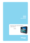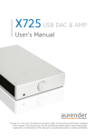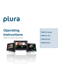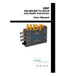
1
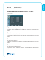
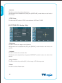
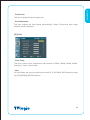
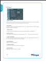
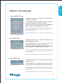
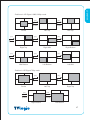
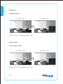
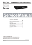
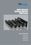
Multi
User’s Manual
Multi-Format LCD Monitors
LVM Series
LVM-071W
Contents
LVM-071W
Warnings ........................................................................................... 2
Features ............................................................................................ 3
Name & Function of Each Part ......................................................... 5
Menu Contents ................................................................................. 9
Other Functions .............................................................................. 15
DVI Digital/Analog Input Signal Format .......................................... 19
Product Specification ..................................................................... 21
Warning
· Always use set voltage.
- DC 12V
· If liquid is spilled on or impacts this product, please disconnect
the product immediately and seek professional help before continued use.
· Keep unit disconnected during extended periods of disuse.
· Keep unit in a well-ventilated place to prevent overheating.
· Do not install the product near any heat-generating equipment.
Also, keep the product out of direct sunlight or dusty areas.
· Only clean the product with a noncommercial, mild and neutral detergent.
· When transporting the product, make use of its original packaging for safer carriage.
FCC (Federal Communications Commission)
This equipment has been tested and found to comply with the limits for class A digital device,
pursuant to part 15 of the FCC Rules. These limits are designed to provide reasonable
protection against harmful interface when the equipment is operated in a commercial
environment.
This equipment generates, uses, and can radiate radio frequency energy, and if not installed
and used in accordance with the instruction manual, may cause harmful interference to radio
communications. Operation of this equipment in a residential to correct the interference at
his own expense
! Warning!! : Change or modifications not expressly approved by the manufacturer
responsible for compliance void the user’s authority to operate the equipment.
Disposal of Old Electrical & Electronic Equipment
(Applicable in the European Union and other European
countries with separate collection systems)
This symbol on the product or on its packing indicates that this product shall not be treated
as household waste. Instead it shall be handed over to the applicable collection point for
the recycling of electrical and electronic equipment. By ensuring this product is disposed
of correctly, you will help prevent potential negative consequence for the environment and
human health, which could otherwise be caused by inappropriate waste handling of this
product. The recycling of materials will help to conserve natural resources.
2
LVM-071W
Features
Multi-Format LVM-071W Series unit has the following features:
Compatible with varied SDI signals
The product is compatible with varied SDI Signals
- 480i,576i,720p,1035i,1080i,1080p,1080psf
Compatible with varied analog signals
The product is compatible with varied analog signals
- Composite, S-Video, Component, RGB
Compatible with varied DVI Digital/Analog Signals
DVI input is standard equipment
Compatible with VGA Signals using DVI-I connection
Waveform/Vector Scope/Audio Level Meter
Waveform & Vector Scope available for SDI Signals
Embedded Audio Level Meter
Audio in & out
Built in Audio Disembedder and Internal Speakers
Stereo Audio out using phone jack
External Audio in for Mono Speaker out
Knob Control
Easy to adjust user configuration using the control knobs.
BLUE ONLY/MONO
H/V delay
3
LVM-071W
Wide Variety of Markers & Safety Areas
Center Marker, Safety Area Marker, Aspect Marker, Display Size(Scan)
Pixel To Pixel
Provides both full screen and unscaled native image.
Wide Screen/LED Backlight
24Bit RGB Interface Panel
DC Compatible
The product is powered by normal 12V source.
Remote control function
Simple remote controllability with single cable connection, no additional
modules required
Additional Features
Active Loop Through/SDI, VESA Mounting Standard, 300:1 contrast ratio, 350 cd/m2
brightness, OSD user interface, Rack Mountable
4
LVM-071W
Name & Function of Each Part
<FRONT>
TALLY
APERTURE
BRIGHT
CHROMA
CONTRAST
VOLUME
ANALOG
POWER
DVI
ENTER
SDI
UP
UNDERSCAN
DOWN
ASPECT
MENU
MARKER/HVDELAY
WAVEFORM/VECTOR SCOPE
BLUE ONLY/ MONO
PHASE
<REAR>
DVI DIGITAL/
DVI ANALOG
SDI-IN
REMOTE
SDI-OUT
CVBS1/B/Pb
CVBS2/G/Y/S-Y
FACTORY PGM
CVBS3/R/Pr/S-C
DC IN
AUDIO IN
AUDIO OUT
5
LVM-071W
<FRONT>
· [ANALOG] button/lamp
Used to select desired Analog Input. (CVB1/2/3, S-Video, Component, RGB)
· [DVI] button/lamp
Used to select desired DVI Input. (DVI DIGITAL, DVI ANALOG)
· [SDI] button/lamp
Used to select SDI Input.
· [UNDERSCAN] button/lamp
Used to transfer from OVER SCAN mode to UNDER SCAN mode.
Mode changes in the order of UNDERSCAN -> OVERSCAN -> PIXEL TO PIXEL ->
UNDERSCAN.
#PIXEL TO PIXEL mode is not available in Graphic mode.
· [ASPECT] button/lamp
Used to toggle aspect ratio in SD from standard to anamorphic.
· [MARKER]/[HVDELAY] button/lamp
Used to show MARKER on the screen. The type of marker at work may be selected on
the main menu. Press and Hold the button to activate the HV Delay mode.
· [BLUE ONLY]/[MONO] button/lamp
You may remove R(red) and G(green) from the input signal and play the screen only
with B(blue) signal. Button may be pressed twice to change the screen to MONO
mode. (This mode uses only Luminance value.)
· [PHASE] button/lamp
Used to change the Phase values.
#Phase is not available in DVI Analog and PAL mode.
· [WAVEFORM]/[VECTOR SCOPE] button/lamp
Used to activate the Waveform or Vector Scope. Pressing the button once will activate
the Waveform, pressing the button twice activates the Vector Scope.
6
LVM-071W
· [MENU] button
Used to activate the OSD menu.
· [UP] button
Used to navigate menu during OSD menu activation. It may also be used to toggle
clockwise through 1:1 quadrants in native scan mode.
· [DOWN] button
Used to navigate menu during OSD menu activation. It may also be used to toggle
counterclockwise through 1:1 quadrants in native scan mode.
· [ENTER] button
Used to confirm a chosen value (or mode) within the OSD menu.
· [POWER] switch
Power On/Off button. If the signal is normal, LED lights in Green. If the signal is unsupported or disconnected, LED flashes in Yellow.
· TALLY
LED indicating monitor’s current status using optional Remote/RS-485.
· [APERTURE] knob
Used to adjust the picture sharpness between MAX(12) and MIN(-12).
#Aperture is not available in DVI Analog mode.
· [BRIGHT] knob
Used to adjust the degree of brightness between MAX(25) and MIN(-25).
· [CHROMA] knob
Used to adjust the saturation between MAX(25) and MIN(-25).
#Chroma is not available in DVI Analog mode.
· [CONTRAST] knob
Used to adjust the contrast ration between MAX(25) and MIN(-25).
· [VOLUME] knob
Used to adjust the volume between MAX(20) and MIN(0).
7
LVM-071W
<REAR>
· REMOTE (RJ-45)
Connection for remote control of monitor.
· DVI DIGITAL/DVI ANALOG (DVI-I)
Input connection for DVI-I.
· SDI-IN (BNC)
SDI signal input terminal.
· SDI-OUT (BNC)
SDI signal output terminal.
· CVBS1/B/Pb (BNC)
Signal input terminal used for COMPOSITE1, RGB B, COMPONENT Pb signals.
· CVBS2/G/Y/S-Y (BNC)
Signal input terminal used for COMPOSITE2, RGB G, COMPONENT Y, SVIDEO signals.
· CVBS3/R/Pr/S-C (BNC)
Signal input terminal used for COMPOSITE3, RGB R, COMPONENT Pr, SVIDEO C signals.
Connector Composite Component
1
CVBS1
2
3
S-Video
Pb
B
No Con.
CVBS2
Y
G
Y
CVBS3
Pr
R
C
· AUDIO IN (Phone jack)
Used to External audio input jack.
· AUDIO OUT (phone jack)
Used to audio output jack.
· FACTORY PGM (40 pins)
Input connector for FACTORY PGM
allowing for firmware updates.
· DC IN (XLR, 4 pins)
Used to supply DC power; 12V.
8
DC IN soket
4
1: GND
4: +12V
1
3
2
LVM-071W
Menu Contents
Below is the description of each function of the menu.
[1] PICTURE
· Brightness
This Item controls the degree of brightness.
#Brightness can be adjusted by using the [BRIGHT] control knob on the front of the
monitor.
· Contrast
This item controls the contrast ratio.
#Contrast can be adjusted by using the [CONTRAST] control knob on the front of the
monitor.
· Chroma
This item controls saturation.
#Saturation can be adjusted by using the [CHROMA] control knob on the front of the
monitor.
· Phase
This item controls Phase value (Hue).
#Phase value can be adjusted by press the [PHASE] button on the front of the
monitor.
9
LVM-071W
· Aperture
This item controls the picture sharpness.
#Sharpness can be adjusted by using the [APERTURE] control knob on the front of
the monitor.
· NTSC Setup
This item sets IRE value in NTSC mode between 0 IRE and 7.5 IRE.
[2] PICTURE (DVI Analog Only)
· Brightness
This Item controls the degree of brightness.
#Brightness can be adjusted by using the [BRIGHT] control knob on the front of the
monitor.
· Contrast
This item controls the contrast ratio.
#Contrast can be adjusted by using the [CONTRAST] control knob on the front of the
monitor.
· Image Position
This item controls the position(H/V) of the image in DVI Analog mode.
· Phase
This item controls Phase value.
10
LVM-071W
· Clocks/Line
This item is adjust timing for signal sync
· Auto Adjustment
This item adjusts the input signal automatically. Phase, Clocks/Line and Image
Position are also adjusted.
[3] Color
· Color Temp
This item controls Color Temperature with presets of 3200K, 5600K, 6500K, 9300K,
and User1, User2, User3 mode.
· User
On User Mode, the user may select and control R, G, & B GAIN, BIAS values by using
the [UP]/[DOWN]/[ENTER] buttons.
11
LVM-071W
[4] Marker
· Marker
This selects the marker type when the MARKER is displayed on the screen.
Compatible MARKER types are as follows:
MODE
MARKER CLASS
HD
16:9, 4:3, 4:3 ON AIR, 15:9,14:9,
SD 16:9
13:9, 1.85:1, 2.35:1, 1.85:1 & 4:3
SD 4:3
16:9
# MARKER may only be activated by pressing the MARKER button on the front of the
monitor.
· Center Marker
This item displays the CENTER MARKER on the screen.
#This function operates only after activating the MARKER function by pressing the
MARKER button on the front of the monitor.
· Safety Area
This item controls the size of the SAFETY AREA between 80%, 88%, 90%, 93%, and 100%.
· Marker Mat
This item darkens the area outside of MARKER setting area. The degree of the matte
is between OFF(0) and (7).
The higher the number the darker MARKER the matte becomes.
12
[5] Remote
REMOTE (RJ-45)
1: Pin1
2: Pin2
3: Pin3
4: Pin4
5: Pin5
6: Pin6
7: Pin7
8: GND
1
8
· Pin1 ~ Pin6
The user may connect RJ-45 jack to the remote terminal on the rear of the unit and
designate a function for each pin.
The selectable functions are as follows:
ANALOG CHANNEL, DVI CHANNEL, DIGITAL CHANNEL
TALLY RED, TALLY GREEN
BLUE ONLY
UNDERSCAN
ASPECT
HVDELAY
16:9 MARKER, 15:9 MARKER, 14:9 MARKER
13:9 MARKER, 4:3 MARKER, 4:3 ON AIR MARKER
1.85:1 MARKER, 2.35:1 MARKER, 1.85:1 & 4:3 MARKER
CENTER MARKER
SAFETY AREA 80%, SAFETY AREA 88%, SAFETY AREA 90%
SAFETY AREA 93%, SAFETY AREA 100%
· Pin7
PIN7 is for POWER ON/OFF use only.
13
LVM-071W
· Marker Color
This item controls Marker color. Selectable colors are white, gray, black, red, green,
and blue.
LVM-071W
[6] System
· System Default
User can use the System Default menu to initialize the values of the monitor excluding
controlled values with the knobs On the front of the monitor.
· Back Light
This item controls the LED backlight setting. The value should be within range
between MIN(0) and MAX(25).
· Audio Volume
This item controls embedded audio volume between MIN(0) and MAX(20).
· Audio Channel
This item set embedded audio channel selects CH1 ~ CH16, Off, and Ext. Audio.
· Audio Level Meter
This item set embedded audio group selects Off, G1+G2, G2+G3, G3+G4, G1+G3,
G1+G4, G2+G4 to activate Audio Level Meter.
· Internal Pattern
Displays internal test pattern.
· Firmware Version
This item is the firmware version of the system.
· Serial Number
Displays the serial number of monitor.
14
LVM-071W
Other Functions
1) ANALOG INPUT Menu
· LVM-071W Series unit is capable of processing varied
ANALOG Input signals.
· Press [ANALOG] button on the front of the monitor and
activate the OSD menu as shown on the left.
Select the input you desire by using the [UP]/[DOWN]
button and press the [ENTER] button to confirm.
#If no image displays after selecting the desired input
mode, check and make sure that your connection is not
lose or disconnected.
#Input resolution displays on the bottom of the OSD screen.
2) DVI INPUT Menu
· LVM-071W Series unit is capable of processing DVI
Digital/Analog input signal.
· Press [DVI] button on the front of the monitor and
activate the OSD menu as shown on the left.
Select the input you desire by using the [UP]/[DOWN]
Button and press the [ENTER] button to confirm.
#If no image displays after selecting the desired input
mode, check and make sure that your connection is not lose
or disconnected.
#Input resolution displays on the bottom of the OSD screen.
3) SDI INPUT Menu
· LVM-071W Series unit is capable of processing single
SDI Input signal.
· Press [SDI] button on the front of the monitor to select
the SDI input. OSD menu displays as shown on the left.
#If no image displays after selecting the desired input
mode, check and make sure that your connection is not lose
or disconnected.
#Input resolution displays on the bottom of the OSD screen.
15
LVM-071W
4) PIXEL TO PIXEL
Pixel To Pixel
CENTER
After two seconds
· LVM-071W monitor’s Pixel to Pixel mode displays input signal without scaling.
· Press [UNDERSCAN] button on the front of the monitor to activate the[Pixel To Pixel] mode.
· In the [Pixel To Pixel] mode, use the [UP]/[DOWN] buttons to toggle between 1:1
scan sections.
Input
Action Button
[UP]
(Clockwise)
Available Modes
Center -> Left Top ->Mid Top -> Right Top ->
Right Mid -> Right Bottom -> Mid Bottom -> Left
Bottom -> Left Mid -> Center -> ….
HD 1080i/1080p
[DOWN]
(Opposite)
[UP]
(Clockwise)
Center -> Left Mid -> Left Bottom -> Mid Bottom
-> Right Bottom -> Right Mid -> Right Top -> Mid
Top -> Left Top -> Center -> …
Center -> Left Top -> Right Top -> Right Bottom
-> left Bottom -> Center -> …
HD 720p
[DOWN]
(Opposite)
Center -> Left Bottom -> Right Bottom ->
Right Top -> Left Top -> Center -> ….
#Pixel To Pixel mode is not available in Graphic mode.
#Pixel To Pixel mode is available in SD mode, but 1:1 sections cannot be rotated
through as with HD sources.
16
LVM-071W
· Positions in HD Signal 1080i/1080p mode
[UP]
[UP]
[DOWN]
[DOWN]
Center
Left Top
Mid Top
[UP]
[UP]
[UP]
[DOWN]
[DOWN]
[DOWN]
Right Top
Right Mid
Right Bottom
[UP]
[UP]
[UP]
[DOWN]
[DOWN]
[DOWN]
Mid Bottom
Left Bottom
Left Mid
· Position in HD Signal 720p mode
[UP]
[UP]
[DOWN]
[DOWN]
Center
Left Top
[UP]
[UP]
[DOWN]
[DOWN]
Right Bottom
Right Top
Left Bottom
17
LVM-071W
5) Waveform
· Waveform Position
Pixel To Pixel
Waveform OFF
Waveform ON
#This function is only available with SDI Input.
6) Vector Scope
· Vector Scope Position
Vector Scope OFF
#This function is only available with SDI Input.
18
Vector Scope ON
1) DVI Analog
Resolution
(Source)
DotClock
[MHz]
fH
(kHz)
f V
(Hz)
Sync
(H/V)
640 x 350 70Hz (IBM)
25.175
31.469
70.086
P/N
640 x 480 60Hz (IBM)
25.175
31.469
59.940
N/P
720 x 400 70Hz (IBM)
28.322
31.469
70.087
N/P
640 x 480 67Hz (MAC)
30.240
35.000
66.667
N/N
832 x 624 75Hz (MAC)
57.284
49.726
74.551
N/N
1152 x 870 75Hz (MAC)
100.00
68.681
75.062
N/N
640 x 480 75Hz (VESA)
31.500
37.500
75.000
N/N
640 x 480 72Hz (VESA)
31.500
37.861
72.809
N/N
800 x 600 56Hz (VESA)
36.000
35.156
56.250
N/N
800 x 600 60Hz (VESA)
40.000
37.879
60.317
P/P
800 x 600 75Hz (VESA)
49.500
46.875
75.000
P/P
800 x 600 72Hz (VESA)
50.000
48.077
72.188
P/P
1024 x 768 60Hz (VESA)
65.000
48.363
60.004
N/N
1024 x 768 70Hz (VESA)
75.000
56.476
70.069
N/N
1024 x 768 75Hz (VESA)
78.750
60.023
75.029
P/P
1152 x 864 75Hz (VESA)
108.00
67.500
75.000
P/P
1280 x 1024 60Hz (VESA)
108.00
60.000
60.000
P/P
1280 x 1024 75Hz (VESA)
135.00
79.976
75.025
P/P
Supported Video Mode
480/60p, 576/50p , 720/50p, 720/60p, 1080/60p
19
LVM-071W
DVI Digital/Analog Input Signal Format
LVM-071W
2) DVI Digital
Resolution
DotClock
[MHz]
fH
(kHz)
f V
(Hz)
Sync
(H/V)
640 x 350 70Hz (IBM)
25.175
31.469
70.086
P/N
640 x 480 60Hz (IBM)
25.175
31.469
59.940
N/P
720 x 400 70Hz (IBM)
28.322
31.469
70.087
N/P
640 x 480 67Hz (MAC)
30.240
35.000
66.667
N/N
832 x 624 75Hz (MAC)
57.284
49.726
74.551
N/N
1152 x 870 75Hz (MAC)
100.00
68.681
75.062
N/N
640 x 480 75Hz (VESA)
31.500
37.500
75.000
N/N
640 x 480 72Hz (VESA)
31.500
37.861
72.809
N/N
800 x 600 56Hz (VESA)
36.000
35.156
56.250
N/N
800 x 600 60Hz (VESA)
40.000
37.879
60.317
P/P
800 x 600 75Hz (VESA)
49.500
46.875
75.000
P/P
800 x 600 72Hz (VESA)
50.000
48.077
72.188
P/P
1024 x 768 60Hz (VESA)
65.000
48.363
60.004
N/N
1024 x 768 70Hz (VESA)
75.000
56.476
70.069
N/N
1024 x 768 75Hz (VESA)
78.750
60.023
75.029
P/P
1152 x 864 75Hz (VESA)
108.00
67.500
75.000
P/P
1280 x 1024 60Hz (VESA)
108.00
60.000
60.000
P/P
1280 x 1024 75Hz (VESA)
135.00
79.976
75.025
P/P
Supported Video Mode
480/60i, 480/60p, 576/50i, 576/50p , 720/50p
Pixel To(Source)
Pixel
720/60p, 1080/50i, 1080/60i,1080/24p
1080/25p, 1080/30p, 1080/50p, 1080/60p
20
Multi
HDMI
TVLogic Product Line
LVM - 084
LVM - 170W (G)
LVM - 400W
LVM - 460W
LVM - 570W
LHM - 400W
LHM - 460W
LHM - 570W
Developed by
LVM - 240W
For more information please visit : www.tvlogic.co.kr
Suite 914 ACE TECHNO TOWER-9, 345-30 Gasan-Dong, GuemChun-Gu, Seoul, Korea
TEL : +82-2-2026-1333
FAX : +82-2-2026-1339
E-mail : [email protected]