1
6
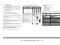
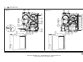
8.2 Installation diagram
A
1
5
B
4
3
6
2
8
8
8
8
8
7
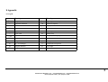
1 Air compressor
2 Dryer
3 By---pass unit
4 Filter (3 micron filtration or better) near dryer air inlet
Safety valves for not exceeding dryer design pressure
5 Tank in position A or in B
Hoses for air connections if the system undergoes vibrations
Suitable dampers if the system undergoes pulsations
6 Outlet filter
7 Oil---Water separator
8 Condensate drain
Manufacturers Distributor, Inc. | www.ZanderSales.com | [email protected]
Phone: (727) 835 - 0649 | Fax: (813) 571 - 0422