1
PC4020 v3.3
(US, UL)
• Installation Manual
DLS-3 v1.3
WARNING: This manual contains information on limitations
regarding product use and function and information on the
limitations as to liability of the manufacturer. The entire
manual should be carefully read.
WARNING
Please Read Carefully
N o t e t o I n s t a l l e rs
This warning contains vital information. As the only individual in contact with system users, it is
your responsibility to bring each item in this warning to the attention of the users of this system.
Sy st e m F a il u res
This system has been carefully designed to be as effective as possible. There are circumstances,
however, involving fire, burglary, or other types of emergencies where it may not provide protection. Any alarm system of any type may be compromised deliberately or may fail to operate as
expected for a variety of reasons. Some but not all of these reasons may be:
■ Inadequate Installation
A security system must be installed properly in order to provide adequate protection. Every installation should be evaluated by a security professional to ensure that all access points and areas are
covered. Locks and latches on windows and doors must be secure and operate as intended. Windows, doors, walls, ceilings and other building materials must be of sufficient strength and construction to provide the level of protection expected. A reevaluation must be done during and after
any construction activity. An evaluation by the fire and/or police department is highly recommended if this service is available.
■ Criminal Knowledge
This system contains security features which were known to be effective at the time of manufacture. It is possible for persons with criminal intent to develop techniques which reduce the effectiveness of these features. It is important that a security system be reviewed periodically to ensure
that its features remain effective and that it be updated or replaced if it is found that it does not provide the protection expected.
■ Access by Intruders
Intruders may enter through an unprotected access point, circumvent a sensing device, evade
detection by moving through an area of insufficient coverage, disconnect a warning device, or
interfere with or prevent the proper operation of the system.
■ Power Failure
Control units, intrusion detectors, smoke detectors and many other security devices require an adequate power supply for proper operation. If a device operates from batteries, it is possible for the
batteries to fail. Even if the batteries have not failed, they must be charged, in good condition and
installed correctly. If a device operates only by AC power, any interruption, however brief, will render that device inoperative while it does not have power. Power interruptions of any length are
often accompanied by voltage fluctuations which may damage electronic equipment such as a
security system. After a power interruption has occurred, immediately conduct a complete system
test to ensure that the system operates as intended.
■ Failure of Replaceable Batteries
This system’s wireless transmitters have been designed to provide several years of battery life
under normal conditions. The expected battery life is a function of the device environment, usage
and type. Ambient conditions such as high humidity, high/low temperatures, or large temperature
fluctuations may reduce the expected battery life. While each transmitting device has a low battery
monitor which identifies when the batteries need to be replaced, this monitor may fail to operate as
expected. Regular testing and maintenance will keep the system in good operating condition.
■ Compromise of Radio Frequency (Wireless) Devices
Signals may not reach the receiver under all circumstances which could include metal objects
placed on or near the radio path or deliberate jamming or other inadvertent radio signal interference.
■ System Users
A user may not be able to operate a panic or emergency switch possibly due to permanent or temporary physical disability, inability to reach the device in time, or unfamiliarity with the correct
operation. It is important that all system users be trained in the correct operation of the alarm system and that they know how to respond when the system indicates an alarm.
■ Smoke Detectors
Smoke detectors that are a part of this system may not properly alert occupants of a fire for a number of reasons, some of which follow. The smoke detectors may have been improperly installed or
positioned. Smoke may not be able to reach the smoke detectors, such as when the fire is in a chimney, walls or roofs, or on the other side of closed doors. Smoke detectors may not detect smoke
from fires on another level of the residence or building.
Every fire is different in the amount of smoke produced and the rate of burning. Smoke detectors
cannot sense all types of fires equally well. Smoke detectors may not provide timely warning of
fires caused by carelessness or safety hazards such as smoking in bed, violent explosions, escaping
gas, improper storage of flammable materials, overloaded electrical circuits, children playing with
matches or arson. Even if the smoke detector operates as intended, there may be circumstances
when there is insufficient warning to allow all occupants to escape in time to avoid injury or death.
■ Motion Detectors
Motion detectors can only detect motion within the designated areas as shown in their respective
installation instructions. They cannot discriminate between intruders and intended occupants.
Motion detectors do not provide volumetric area protection. They have multiple beams of detection and motion can only be detected in unobstructed areas covered by these beams. They cannot
detect motion which occurs behind walls, ceilings, floor, closed doors, glass partitions, glass doors
or windows. Any type of tampering whether intentional or unintentional such as masking, painting, or spraying of any material on the lenses, mirrors, windows or any other part of the detection
system will impair its proper operation.
Passive infrared motion detectors operate by sensing changes in temperature. However their effectiveness can be reduced when the ambient temperature rises near or above body temperature or if
there are intentional or unintentional sources of heat in or near the detection area. Some of these
heat sources could be heaters, radiators, stoves, barbeques, fireplaces, sunlight, steam vents, lighting and so on.
■ Warning Devices
Warning devices such as sirens, bells, horns, or strobes may not warn people or waken someone
sleeping if there is an intervening wall or door. If warning devices are located on a different level of
the residence or premise, then it is less likely that the occupants will be alerted or awakened. Audible warning devices may be interfered with by other noise sources such as stereos, radios, televisions, air conditioners or other appliances, or passing traffic. Audible warning devices, however
loud, may not be heard by a hearing-impaired person.
■ Telephone Lines
If telephone lines are used to transmit alarms, they may be out of service or busy for certain periods
of time. Also an intruder may cut the telephone line or defeat its operation by more sophisticated
means which may be difficult to detect.
■ Insufficient Time
There may be circumstances when the system will operate as intended, yet the occupants will
not be protected from the emergency due to their inability to respond to the warnings in a
timely manner. If the system is monitored, the response may not occur in time to protect the
occupants or their belongings.
■ Component Failure
Although every effort has been made to make this system as reliable as possible, the system may
fail to function as intended due to the failure of a component.
■ Inadequate Testing
Most problems that would prevent an alarm system from operating as intended can be found by
regular testing and maintenance. The complete system should be tested weekly and immediately
after a break-in, an attempted break-in, a fire, a storm, an earthquake, an accident, or any kind of
construction activity inside or outside the premises. The testing should include all sensing devices,
keypads, consoles, alarm indicating devices and any other operational devices that are part of the
system.
■ Security and Insurance
Regardless of its capabilities, an alarm system is not a substitute for property or life insurance. An
alarm system also is not a substitute for property owners, renters, or other occupants to act prudently to prevent or minimize the harmful effects of an emergency situation.
Limited Warranty
Digital Security Controls Ltd. warrants the original purchaser that for a period of twelve months from the
date of purchase, the product shall be free of defects in materials and workmanship under normal use. During the warranty period, Digital Security Controls Ltd. shall, at its option, repair or replace any defective
product upon return of the product to its factory, at no charge for labour and materials. Any replacement
and/or repaired parts are warranted for the remainder of the original warranty or ninety (90) days, whichever is longer. The original purchaser must promptly notify Digital Security Controls Ltd. in writing that
there is defect in material or workmanship, such written notice to be received in all events prior to expiration of the warranty period. There is absolutely no warranty on software and all software products are sold
as a user license under the terms of the software license agreement included with the product. The Customer assumes all responsibility for the proper selection, installation, operation and maintenance of any
products purchased from DSC. Custom products are only warranted to the extent that they do not function
upon delivery. In such cases, DSC can replace or credit at its option.
The warranty for international customers is the same as for any customer within Canada and the United
States, with the exception that Digital Security Controls Ltd. shall not be responsible for any customs fees,
taxes, or VAT that may be due.
To obtain service under this warranty, please return the item(s) in question to the point of purchase. All
authorized distributors and dealers have a warranty program. Anyone returning goods to Digital Security
Controls Ltd. must first obtain an authorization number. Digital Security Controls Ltd. will not accept any
shipment whatsoever for which prior authorization has not been obtained.
This warranty applies only to defects in parts and workmanship relating to normal use. It does not cover:
• damage incurred in shipping or handling;
• damage caused by disaster such as fire, flood, wind, earthquake or lightning;
• damage due to causes beyond the control of Digital Security Controls Ltd. such as excessive voltage,
mechanical shock or water damage;
• damage caused by unauthorized attachment, alterations, modifications or foreign objects;
• damage caused by peripherals (unless such peripherals were supplied by Digital Security Controls Ltd.);
• defects caused by failure to provide a suitable installation environment for the products;
• damage caused by use of the products for purposes other than those for which it was designed;
• damage from improper maintenance;
• damage arising out of any other abuse, mishandling or improper application of the products.
In addition to the items which void the Warranty, the following items shall not be covered by Warranty: (i)
freight cost to the repair centre; (ii) products which are not identified with DSC's product label and lot number or serial number; (iii) products disassembled or repaired in such a manner as to adversely affect performance or prevent adequate inspection or testing to verify any warranty claim. Access cards or tags returned
for replacement under warranty will be credited or replaced at DSC's option. Products not covered by this
warranty, or otherwise out of warranty due to age, misuse, or damage shall be evaluated, and a repair estimate shall be provided. No repair work will be performed until a valid purchase order is received from the
Customer and a Return Merchandise Authorisation number (RMA) is issued by DSC's Customer Service.
Digital Security Controls Ltd.’s liability for failure to repair the product under this warranty after a reasonable number of attempts will be limited to a replacement of the product, as the exclusive remedy for breach
of warranty. Under no circumstances shall Digital Security Controls Ltd. be liable for any special, incidental, or consequential damages based upon breach of warranty, breach of contract, negligence, strict liability,
or any other legal theory. Such damages include, but are not limited to, loss of profits, loss of the product or
any associated equipment, cost of capital, cost of substitute or replacement equipment, facilities or services,
down time, purchaser’s time, the claims of third parties, including customers, and injury to property. The
laws of some jurisdictions limit or do not allow the disclaimer of consequential damages. If the laws of
such a jurisdiction apply to any claim by or against DSC, the limitations and disclaimers contained here
shall be to the greatest extent permitted by law. Some states do not allow the exclusion or limitation of incidental or consequential damages, so that the above may not apply to you.
This warranty contains the entire warranty and shall be in lieu of any and all other warranties, whether
expressed or implied (including all implied warranties of merchantability or fitness for a particular purpose)
and of all other obligations or liabilities on the part of Digital Security Controls Ltd. Digital Security Controls
Ltd. neither assumes responsibility for, nor authorizes any other person purporting to act on its behalf to modify or to change this warranty, nor to assume for it any other warranty or liability concerning this product. This
disclaimer of warranties and limited warranty are governed by the laws of the province of Ontario, Canada.
WARNING: Digital Security Controls Ltd. recommends that the entire system be completely tested
on a regular basis. However, despite frequent testing, and due to, but not limited to, criminal tampering or electrical disruption, it is possible for this product to fail to perform as expected.
Digital Security Controls Ltd. will at its option repair or replace out-of-warranty products which are
returned to its factory according to the following conditions. Anyone returning goods to Digital Security
Controls Ltd. must first obtain an authorization number. Digital Security Controls Ltd. will not accept any
shipment whatsoever for which prior authorization has not been obtained.
Products which Digital Security Controls Ltd. determines to be repairable will be repaired and returned. A
set fee which Digital Security Controls Ltd. has predetermined and which may be revised from time to
time, will be charged for each unit repaired.
Products which Digital Security Controls Ltd. determines not to be repairable will be replaced by the nearest equivalent product available at that time. The current market price of the replacement product will be
charged for each replacement unit.
Ta ble of Contents
Section 1: Introduction
1.1
1.2
Section 2: Installation and Wiring
2.1
2.2
2.3
2.4
2.5
2.6
2.7
2.8
2.9
2.10
2.11
2.12
2.13
2.14
2.15
18
Partition Keypads .................................................................... 18
Global Keypads ....................................................................... 18
Keypad Toggle Options ......................................................... 18
Keypad Time-out .................................................................... 19
Keypad Blanking ..................................................................... 19
Fire, Auxiliary and Panic Keys .............................................. 19
Keypad Lockout ...................................................................... 19
Keypad Tampers ..................................................................... 20
Alarm Memory Display ......................................................... 20
Zone Bypass Display .............................................................. 20
Function Key Programming .................................................. 20
Section 7: Installer and Access Codes
7.1
7.2
7.3
7.4
7.5
7.6
7.7
7.8
7.9
7.10
13
Zone Supervision .................................................................... 13
Creating Partitions .................................................................. 13
Adding Zones to Partitions ................................................... 14
Zone Programming ................................................................. 14
Section 6: Keypad Operation
6.1
6.2
6.3
6.4
6.5
6.6
6.7
6.8
6.9
6.10
6.11
11
Enrolling Keypads and Modules .......................................... 11
Deleting Modules .................................................................... 11
Confirming Modules .............................................................. 12
Enrolling AML Devices .......................................................... 12
Section 5: Partitions and Zones
5.1
5.2
5.3
5.4
9
Introduction to Programming ................................................. 9
Programming by Reference Number ..................................... 9
Programming Decimal Data .................................................... 9
Programming Hexadecimal Data ......................................... 10
Programming Toggle Options .............................................. 10
Section 4: Module Enrollment
4.1
4.2
4.3
4.4
2
Planning the System ................................................................. 2
Terminal Descriptions .............................................................. 2
Wire Routing for Power and Non-Power Limited ............... 2
Current Ratings – Alarm Control Panel and Modules ........ 2
Combus Operation and Wiring .............................................. 3
Zone Wiring ............................................................................... 4
Specialized Zone Wiring .......................................................... 5
Programmable Output Wiring ................................................ 5
AML Device Wiring .................................................................. 5
Wiring Powered Devices (AUX, SAUX+) .............................. 6
Telephone Line Wiring ............................................................. 7
Bell Output Wiring (BELL+ and BELL-) ................................ 7
Earth Ground Wiring ............................................................... 7
Applying Power (AC and Battery) ......................................... 7
Lithium Batteries ....................................................................... 8
Section 3: How to Program
3.1
3.2
3.3
3.4
3.5
1
Out of the Box ............................................................................ 1
Specifications and Features ..................................................... 1
22
Installer’s Code ........................................................................ 22
Installer-Programmed Access Codes ................................... 22
Programming Access Codes .................................................. 22
Modify An Existing Code ...................................................... 24
Change User Code Options ................................................... 24
Delete An Existing Code ........................................................ 25
Special Codes ........................................................................... 25
Guard Code .............................................................................. 26
Access Code Options .............................................................. 26
Access Levels ........................................................................... 26
Section 8: Arming and Disarming
8.1
8.2
Section 9: Entry and Exit Delay
9.1
9.2
27
Arming and Disarming Options ........................................... 27
Automatic Arming .................................................................. 27
28
Entry and Exit Delay Times ................................................... 28
Entry and Exit Delay Options ................................................ 28
Section 10: System Programming
29
10.1 AC/DC Power Options .......................................................... 29
10.2 Bell Circuit Supervision .......................................................... 29
10.3 Clock Options ........................................................................... 29
10.4 Event Messages ........................................................................ 30
10.5 Swinger Shutdown .................................................................. 30
10.6 Tampers .................................................................................... 30
10.7 Telephone Line Supervision .................................................. 31
10.8 Test Transmissions .................................................................. 31
10.9 Transmission Delay ................................................................. 31
10.10 Cross Zone (Police Code) Alarm .......................................... 32
10.11 System Label ........................................................................... 32
10.12 Hourly Print ............................................................................ 32
Section 11: Programmable Outputs
11.1
11.2
11.3
11.4
Section 12: Communications Programming
12.1
12.2
12.3
12.4
12.5
12.6
12.7
33
Main Panel Outputs ................................................................33
Programming Output Options for Modules .......................33
Programmable Output Options ............................................ 33
Output Pulse Times ................................................................. 35
37
Telephone Numbers ................................................................ 37
Account Numbers ................................................................... 37
Dialing Parameters .................................................................. 37
Communicator Toggle Options ............................................. 37
Dialer Direction ........................................................................ 39
Communicator Formats .......................................................... 39
Reporting Codes ...................................................................... 40
Section 13: Downloading
41
13.1 Downloading Options ............................................................ 41
13.2 Periodic Call-up ....................................................................... 41
13.3 PC-Link ..................................................................................... 41
Section 14: Event Scheduling
14.1
14.2
14.3
14.4
14.5
42
Date Schedules ......................................................................... 42
Holiday Groups ....................................................................... 42
Open/Close Suppression ....................................................... 42
Arming/Disarming Schedules .............................................. 43
Scheduled AMS-220/220T Smoke Detector Test ................43
Section 15: LINKS Communications
44
15.1 LINKS1000 (Cellular Communications) .............................. 44
15.2 LINKS2XXX (Long-range Radio Communications) ........... 44
15.3 T-Link TCP/IP Communications) ........................................ 44
Section 16: Diagnostics and Troubleshooting
16.1
16.2
16.3
16.4
16.5
45
General Diagnostics ................................................................45
Restoring Factory Default Programming ............................. 45
Hardware Reset ....................................................................... 45
Viewing Trouble Conditions ................................................. 45
System Fault Squawk .............................................................. 46
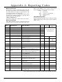
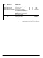
• Appendix A: Reporting Codes
48
• Appendix B: Zone Reporting Codes
51
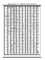
• Appendix C: ASCII Characters
52
i
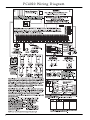
P C 40 2 0 Wi r i n g D i a g r a m
ii
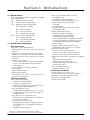
S ec tion 1: Intro d u cti o n
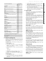
1.1 Out Of The Box
Please verify that the following components are included
in the PC4020 package.
❑ 1 PC4050C or PC4001C cabinet
❑ 1 Version 3.3 main control module
❑ 1 Hardware package which includes:
❑ 32 EOL resistors (5600Ω)
❑ 1 Black cabinet plug
❑ 1 Green ground strap
❑
PCB mounting standoffs
❑ 1 set of documents which includes:
❑ 1 Installation Manual
❑ 1 Programming Worksheets
❑ 1 Instruction Manual
1.2 Specifications and Features
Main Control Panel
• AC Input – 16 VAC, 40VA minimum
• Battery Charger – 350 mA to charge 12VDC lead-acid
batteries
• Bell Circuit – 12 VDC, 700 mA continuous maximum
• Auxiliary Power Output: 12 VDC, 500 mA maximum
• Switched Auxiliary Power Output 12 VDC, 300 mA
maximum
• PGM 1 & 2 – two options:
• 12 VDC, 50 mA maximum each as standard outputs
• 12 VDC, 170 mA maximum each when used for
addressable loop
• 4-wire Combus power – 500 mA maximum
• 16 Zone inputs
• Supervised dialer output
• Earth ground connection
• All outputs rated to operate over the range of 11.6 to
12.6V for UL Listed systems.
Expansion Capabilities
• Up to 128 zones total using
• PC4108A 8-zone input modules
• PC4116 16-zone input modules
• PC4164 v2.x wireless receivers and wireless devices
• PGM outputs for addressable devices
• Up to 16 keypads total using
• LCD4501 keypad (with function keys) - v2.0 or later
• LCD4500 keypad - v2.02 for function key support
(number keys 1-5)
• Up to 144 low power outputs total using
• PC4216 low power output modules (v2.1 required
for Temporal Fire option)
• Up to 64 relay outputs total using
• PC4204 quad relay and power supply module; also
for Combus repower (v2.1 required for Temporal
Fire option)
• PC4204CX Combus repeater
*
**
• Up to 8 supervised bell outputs total using
• PC4702BP (up to 4)
• Up to 32 card access-controlled doors
• PC4820 dual card reader modules (up to 16)
• System Printer/DVACS* output using
• DataLink**
• PC440X module
• Dual phone line and Class ‘B’ fire zones using
• PC4701 fire module
• Backup communication using
• LINKS1000 cellular communicator
• LINKS2150 long-range transmitter
• LINKS2450 long-range transmitter**
• Any compatible alternate communication module**
• T-Link TCP/IP Ethernet Communicator (see the
T-Link Installation Manual part no. 29001007)
• Skyroute Max
• Telephone access & automation items using
• ESCORT4580 Audio Assistant (v1.3 or greater)
• Remote annunciation using
• PC4612 – 12-zone point annunciator
• PC4632 – 32-zone point/graphic annunciator
• PC4664 – 64-zone point/graphic annunciator
• Central station talk/listen** and intercom capabilities
using:
• PC4936 audio interface module
• PC4937 8-port expansion module
• LCD4501/4500 keypad and audio station
• PC5921 audio stations
• Up to 32 telephone entry doors
• PC4850 module (up to 16)**
Downloading Capabilities
• Downloading Software: DLS-3 v1.3**
• PC-Link connector – for local upload/download
• End user PC-Link using PC4401 as isolator**
• DataLink access using PC4401
• T-Link TCP/IP module
DVACS is a registered trademark of Electro Arts Limited
Not UL Listed. Do not use in conjunction with UL Listed systems.
1
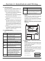
Section 2: Installation and Wi ring
2.1 Planning the System
The speed and efficiency of installing a MAXSYS system
will be greatly enhanced by planning the installation. As a
minimum, the following checklist should be used to
ensure that all of the details have been considered:
❑ Draw a diagram of the installation showing the location of the main panel, all keypads, zone inputs, bell
outputs, relay outputs and annunciators.
❑ Indicate all partitions on the diagram. Decide which
zones, bell and relay outputs, keypads and remote
annunciators belong to each partition.
❑ Determine where each system module is going to be
located and how far each module will be from the
main panel.
❑ Determine the current draw on the main panel and
each system component used to ensure the system
requirements can be met (see 2.4 ‘Current Ratings –
Alarm Control Panel and Modules‘). Calculate each
wire run using the Combus wiring guidelines. Determine which wire gauge should be used and where to
place PC4204/PC4204CX modules to re-power the
Combus.
❑ For Addressable devices, determine where each device
is to be located and consult the Addressable Loop wiring guidelines to determine wire gauge and wiring
lengths (see 2.9 ‘AML Device Wiring‘)
Terminals
Description
TIP, RING,
T1, R1
Telephone Line Terminals
EGND
Earth Ground Connection. A ground connection
assembly is included with the control panel.
Please refer to the control panel wiring diagram
for ground connection instructions.
2.3 Wire Routing for Power and Non-Power
Limited
All wiring entry points are designated by the arrows. All
circuits are classified UL installation power limited except
for the battery leads which are not power limited.
A minimum ¼” (7mm) separation must be maintained at
all points between power limited and non-power limited
wiring and connections.
NOTE: Wire entry for power limited wiring must be
separated by a different entry access from non-power
limited wiring.
2.2 Terminal Descriptions
The following terminals appear on the alarm control
panel:
Terminals
Description
Red and
Black Leads
Battery Connection. WARNING: Do not connect the battery or transformer until all
other wiring is complete.
AC
Power Terminals. WARNING: Connect the battery before connecting the AC. Do not connect the battery or transformer until all
other wiring is complete.
AUX+ and
AUX-
Auxiliary Power, 500mA MAX
SAUX+
Switched Auxiliary Power, 300mA MAX
BELL+ and
BELL-
Bell/Siren Power. These terminals are used for
powering bells, sirens or other devices requiring
steady output voltage on alarm; 700mA MAX
PGM1 and
PGM2
Programmable Output Terminals.
50mA MAX (standard output) or
170mA MAX (addressable loop)
RED, BLK,
YEL, GRN
Combus Terminals. The Combus is used by the
panel and the modules to communicate with
each other. RED and BLK are used for power, and
YEL and GRN for data. NOTE: The four Combus
terminals of the main panel must be connected to the four Combus terminals or
wires of all modules. For instructions
regarding Combus wiring, refer to Section
2.4 ’Combus Operation and Wiring’.
Z1 to Z16
2
Zone Input Terminals. Zone inputs Z1 to Z16 are provided for wiring zones on the alarm control panel
NOTE: A minimum 1/4" (6.4mm)
separation must be maintained at all
points between power limited & nonpower limited wiring and connections.
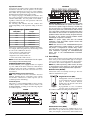
2.4 Current Ratings – Alarm Control Panel and
Modules
In order for the system to operate properly, the power output of the alarm control panel and power supply modules
cannot be exceeded. Use the data below to ensure that the
available current is not exceeded.
Alarm Control Panel
AUX - 500mA available for devices connected to the AUX,
SAUX+ and PGM terminals and modules connected to
Combus terminals. At least 100mA must be reserved for
the Combus. To calculate the amount of current required,
complete the following chart:
Main Panel Current Calculation
Maximum (Standby or Alarm)
AUX (500mA max.)
SAUX+ (300mA max.)
I n s t a l l a t i o n
W i r i n g
Quantity
Total (mA)
Combus Current Selection Chart
PGM1 (50/170mA max.*)
Item
PGM2 (50/170mA max.*)
Combus (500mA max.)**
Current (mA)
x
PC4850
135
x
PC4936*
65
T-Link
150
Skyroute
30
Total Combus Current =
Total (must not exceed 500mA)
*PGM1/PGM2 (Standard Output) = 50mA max.
NOTE: PGM1/PGM2 (Addressable Loop) = 170mA max.
NOTE: To calculate Addressable Loop current, see 2.9
‘AML Device Wiring‘.
**See ‘Combus Current Calculation Chart’ below.
NOTE: For UL Listed applications, the total standby and
alarm current cannot exceed 900mA.
Module Ratings
The current draw of compatible modules is listed below:
Device .................................................Current Draw (mA)
Keypad (LCD45XX)......................................................... 50
PC4108A Zone Expander ............................................... 30
PC4116 Zone Expander................................................... 30
PC4164 Wireless Receiver............................................. 110
PC4701 Fire Module ........................................................ 35
PC4702BP Dual Bell Output Module............................ 75
PC4204 Relay Output Module ....................................... 30
PC4204CX Combus Repeater......................................... 30
PC4216 Low Current Output Module .......................... 15
ESCORT4580 Audio Assistant ..................................... 150
PC4401 Interface Module ............................................... 35
PC4820 Access Control Module .................................... 35
PC4936 Audio Interface Module ................................... 65
PC4850 Module .............................................................. 135
Calculating Total Current Requirement
Once you have determined which modules will draw
power from the main panel, use the following chart to calculate the Combus current.
Combus Current Selection Chart
Item
Keypad
PC4108A*
Current (mA)
x
50
x
30
x
Quantity
Current required for connected devices =
PC4116*
30
x
Current required for connected devices =
PC4164
110
x
PC4701
35
PC4702BP
75
x
PC4204/PC4204CX
30
x
PC4216*
15
x
Current required for connected devices =
ESCORT4580
150
PC4401
35
x
PC4820
35
x
Total Combus Current =
Total (mA)
NOTE: *These units draw current from the Combus to
power devices external to the module. This current must
be added to the total Combus current. See manufacturer's specifications for the current draw of each
device. Each LED assembly draws up to 20mA of current.
2.5 Combus Operation and Wiring
The Combus is used by the control panel and the modules
to communicate with each other. The four Combus terminals of the main panel must be connected to the four Combus terminals or wires of all modules.
Modules can be home run, connected in a daisy chain or
T-tapped anywhere on the Combus.
The following rules MUST be followed when wiring the
Combus:
1. The Combus must be run in minimum 22-gauge wire.
2. No module can be more than 1000' (305m) in cable
length from the main control panel.
3. Shielded wire should only be used in areas that
present excessive RF noise or electromagnetic interference. If shielded wire is used, the maximum distance a
module can be located from the main panel is significantly reduced. Check the capacitance limit of the wire
to calculate the maximum distance (see ’Capacitance
Limits’ below).
4. The total capacitance of the Combus wiring must not
exceed 80nF (see ’Capacitance Limits’ below).
5. Do not run Combus wire runs in parallel with AML
wire runs. Maintain minimum 2” separation between
the cables.
Line Loss
When current is drawn through a piece of wire, voltage
will be lost due to the wire’s resistance. This voltage loss
must be considered for all installations.
To ensure proper operation, at least 12.5VDC must be
applied to all modules on the system (when AC is applied
and the battery is fully charged). If less than 12.5VDC is
applied, system operation will be adversely affected.
To correct the problem, try any or all of the following:
1. Connect a PC4204/PC4204CX power supply near the
module to provide power to the Combus.
2. Reduce the length of the Combus run to the module.
3. Increase the gauge of wire.
3
S EC T I O N 1 2 3 4 5 6 7 8 9 1 0 1 1 1 2 13 14 1 5 1 6
a n d
Capacitance Limits
An increase in capacitance on the Combus will affect data
transmission and will cause the system to slow down.
Capacitance will increase for every foot of wire added to
the Combus. The capacitance rating of the wire used will
determine the maximum length of the Combus.
For example, 22-gauge, non-shielded, 4-conductor wire
has a typical capacitance rating of 20 picofarads per foot
(which is 20nF/1000’). For every 1000' of wire added –
regardless of where it is run – the capacitance of the Combus will increase by 20nF.
The following chart indicates the total Combus wire
allowed depending on the capacitance rating of the wire
used:
Wire Capacitance per
1000'(300m)
TOTAL Combus Wire
Length
15nF
5300'/1616m
20nF
4000'/1220m
25nF
3200'/976m
30nF
2666'/810m
35nF
2280'/693m
40nF
2000'/608m
Wires run in parallel also increase Combus capacitance.
For example, when using 20nF wire, the following would
be some of the combinations allowed:
• Four wire runs at 1000'/305m each
• Six wire runs at 666'/203m each
• Eight wire runs at 500'/152m each
• 10 wire runs at 400'/122m each etc…
NOTE: Contact the wire manufacturer for the capacitance ratings of the wire being used.
PC4204/PC4204CX Power Supply
PC4204/PC4204CX power supply modules are required
to power additional modules and devices when the total
current from the main panel is insufficient. A PC4204/
PC4204CX should also be used if excessive line loss is
encountered.
PC4204/PC4204CX Current Requirement
AUX - 1.0A available for devices connected to the AUX
terminal, including devices connected to relay outputs
and modules connected for Combus repower (see 2.5
‘Combus Operation and Wiring‘).
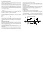
Combus Repower
Only Relay 1 on the PC4204/PC4204CX can be used for
Combus repower. The Combus must be wired to the
PC4204/PC4204CX according to the following diagram
for Combus repower:
PC4204
PC4204CX
IMPORTANT NOTE: Do not use any power supply other
than the PC4204/PC4204CX to repower the Combus. In
the event of a power surge or transient, a module may
lock up and cease to communicate with the control
panel. If the panel loses communication with the module, it will initiate a module reset and will power down
the Combus for five seconds in an attempt to reset the
problem module. After five seconds, the panel will reapply power to the Combus and the problem module
should begin to operate as intended.
NOTE: If a power supply other than the PC4204/
PC4204CX is used, the Combus repower function will
not operate as intended.
NOTE: New versions of the PC4204/PC4204CX power
supply module have a jumper marked ‘J1’. Ensure that
this jumper is configured for ’Combus Relay’. Otherwise, the power reset function will not operate. For
more information regarding the PC4204/PC4204CX,
please refer to the PC4204/PC4204CX Installation
Instructions.
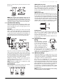
2.6 Zone Wiring
Zones on the system are wired according to the diagrams
below. Once you have selected which type of zone supervision you require, you must program the ’Zone Supervision’ section. See 5.1 ‘Zone Supervision‘ for instructions.
NOTE: Fire, LINKS Supervisory, LINKS Answer, AC Delay
or Forced Answer zones always use single EOL supervision, regardless of the programmed zone supervision.
No End of Line (No EOL)
All No EOL zones are normally closed loops. The zone
will be violated when it is open.
Single End of Line (EOL)
All Single EOL zones have a 5600Ω resistor across them. If the zone is shorted or
open, it will be violated. Resistors
should always be placed at the device
end of the wire run.
If programmed as a fire or waterflow
zone, the open zone will generate a trouble condition and the short will generate an alarm.
Double End of Line (DEOL)
All Double EOL zones have two 5600Ω resistors across
them. DEOL loops will allow the panel to detect zone
faults, zone tampers, violated zones and restored zones.
4
I n s t a l l a t i o n
NOTE: Only normally closed detection devices can be
used with this type of zone supervision. Only one normally closed contact can be connected to each zone;
multiple detection devices/ ontacts on one loop are not
allowed, the tamper condition will not be monitored.
W i r i n g
LINKS Supervisory Zone
This zone is for use with a LINKS1000/LINKS2150/
LINKS2450 only. If the LINKS experiences a trouble condition, a LINKS output can be used to violate this zone type
and the event will be reported to the central station.
See the corresponding LINKS Installation Manual for wiring information.
LINKS Answer Zone
This zone is for use with a LINKS1000 only. In case of a telephone line failure, the panel can be uploaded/downloaded
via the cellular network. If the LINKS detects an incoming
call, it will activate an output that can be used to violate this
zone type. This will force the panel to answer the cellular
call and will begin communications with the downloading
computer. This zone must be programmed as LINKS
Answer and wired according to the following diagram:
2.7 Specialized Zone Wiring
Some zones require wiring configurations unique to the
selected zone type. These zones are listed below. For information regarding the various zone types, please see 5.4
‘Zone Programming‘.
Fire Zone
This zone type uses normally open contacts. The zone will
initiate a fire alarm when the loop is shorted (contacts
close). A Fire Zone trouble will be generated when the loop
is opened (wire break). Typically, fire alarm initiating contacts originate from 4-wire smoke detectors. These types of
detectors must be wired as shown in the diagram below.
AC Delay Zone
This zone is for use with a LINKS1000. If the LINKS experiences an AC trouble condition, a LINKS output can be
used to violate this zone type and the event will be
reported to the central station.
See the corresponding LINKS Installation Manual for wiring information.
2.8 Programmable Output
Wiring
The power for the 4-wire detectors must be supervised
with an end-of-line relay (RM-1). The contacts of that relay
are wired in series with the zone end-of-line resistor. With
the relay energized, the relay contacts are closed and the
zone is normal. If the power is lost, the relay de-energizes,
the contacts open and a zone trouble is initiated.
Multiple fire initiating normally open contacts may be
used in parallel on the loop. Do not include burglary or
other types of devices on a fire zone.
NOTE: Minimum 18 AWG wire is required for Listed
Residential Fire Alarm Systems.
Keyswitch Zone
Zones programmed as keyswitch arming zones must be
wired according to one the following diagrams:
The PGM output is a programmable terminal and will connect
to +12V when activated. The terminal can source a maximum
current of 50mA. If the desired
current is higher than 50mA, a
relay will be required. To connect the relay, refer to the above diagram. Each output can
be programmed as one of numerous available output
options. See 11.3 ‘Programmable Output Options‘ for a
complete list of PGM output options.
2.9 AML Device Wiring
Addressable Multiplex Loop (AML) devices use a 2-wire
connection for power and to communicate to and from the
control panel. All detectors are designed for low power
consumption to make for an efficient system.
The system can accommodate up to 128 addressable
devices. Connect the addressable loop to PGM1 and/or
PGM2, when programmed for AML operation. If only one
loop is used, then all 128 devices can be on the loop. If both
PGM1 and PGM2 are used, the 128 devices can be divided
between the two in any ratio that suits the application.
For instructions on configuring PGM1/PGM2 for AML
operation, and for AML device enrollment, see 4.4 ‘Enrolling AML Devices‘.
NOTE: The panel must be powered down when adding
or removing devices from the AMLbus.
5
S EC T I O N 1 2 3 4 5 6 7 8 9 1 0 1 1 1 2 13 14 1 5 1 6
Resistors should always be placed at the device end of
the wire run.
a n d
Addressable Devices
The following addressable devices are available:
• AMS-220/220T smoke detector with optional temperature sensor*
• AMB-300 PIR detector
• AMB-500 ceiling PIR detector
• AMB-600 dual PIR detector
• AMA-100 glass break detector
• AMP-700 magnetic door/window contact
• AMP-701 contact input module
• AMP-702 fire alarm contact input module
• AMX-400 repeater/isolator module
• AML-770 isolator module
*Fire alarm devices cannot be placed on the same loop as
burglary devices.
Addressable Loop Response Time
The overall system response time for devices on the AML
loop depends on how many devices are on each loop.
The response times below include three factors:
• input debounce time
• addressable reporting and confirmation time
• processing time required by the panel to activate the
output
Response Time (seconds)
Response Time = 1.348 + (0.036 x # of zones)
Use this formula on the PGM with the greater number of
zones to find the loop response for both PGMs.
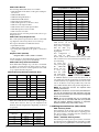
Addressable Loop Current Calculation
Each addressable multiplex loop can draw a maximum
of 170mA of current from the main panel. In order to
determine the amount of current required for the AML
loop, complete the following chart:
Addressable Loop Current Calculation Chart
Item
Current (mA)
x
AMS-220/T
0.8
x
AMB-300
2.5
x
AMB-500
.75
x
AMB-600
3.5
x
AMA-100
3.5
x
AMP-700
0.8
x
AMP-701
0.8
x
AMP-702
0.8
x
Quantity
Total (mA)
50
600/183
1250/381
60
500/152
980/298
70
400/122
800/244
80
321/98
720/220
90
250/76
500/152
100
200/61
310/95
110
165/50
220/67
120
135/41
155/47
130
115/35
130/39
140
106/32
126/38
150
100/30
124/37
160
98/29
122/36
170
96/28
120/35
Addressable Loop Wiring
AML devices can be
home-run, connected in a
daisy chain, or T-tapped.
Wire the AML loop
according to the following diagram:
This configuration is
only used for AML
devices. Please see the Installation Instructions provided
with each device for more information regarding operation and wiring.
For longer wire
runs, you can split
the
addressable
devices onto two
or more loops
from the COM
and PGM terminals. For example,
32 AMB-300 detectors (2.5mA each) take 80mA total. In
one 18AWG wire run, this would allow a maximum length
of 720 feet (220 m). If you split the 32 devices into two wire
runs of 16 detectors each, using 18AWG wire, each wire
run could be 1736 feet (529 m) long. See the diagram above.
NOTE: No end-of-line resistors are required when
installing these devices.
NOTE: Once the devices are connected, the PGM terminal must be configured for AML operation and each
device must be enrolled. See Section 4.4 ’Enrolling AML
Devices’ for instructions.
Total Current =
When more AML devices are added to a single loop, the
current draw increases. The loop wire length must be
limited to the following distances depending on the total
loop curent:
Loop Current vs. Wiring Distance
6
Loop Current vs. Wiring Distance
TOTAL LOOP
22 AWG
18 AWG
CURRENT(MA)
DISTANCE(FT/M)
DISTANCE(FT/M)
10
2880/878
5143/1568
20
1620/494
3645/1111
30
1010/308
2520/768
40
771/235
1736/529
NOTE: Do not use shielded wire runs in parallel with
each other. Do not run either AML wire run in parallel
with the Combus. Maintain minimum 2” separation
between all AML wiring and Combus wiring.
2.10 Wiring Powered Devices (AUX, SAUX+)
AUX – Auxiliary Power
These terminals can be used to power motion detectors,
glass break detectors and other devices requiring power.
The AUX (positive) and GND (negative) terminals can
provide up to 500mA of current.
SAUX+ – Switched Auxiliary Power
This terminal provides positive power (12VDC) and can be
de-energized via the [*][7][2] keypad command (provided
that the output is programmed as Command Output #2).
I n s t a l l a t i o n
a n d
W i r i n g
2.11 Telephone Line Wiring
The telephone terminals provide connections to the
incoming telephone lines for central station reporting. The
wires from the RJ-31X jack must be connected in the following manner:
2.13 Earth Ground Wiring
NOTE: There must be no other telephone equipment
connected between the control panel and the incoming telephone line (e.g. answering machines, fax
machines, telephones, etc.). Ensure that plugs and
jacks meet the dimension, tolerance and metallic plating requirements of 47 CFR Part 68 Subpart F.
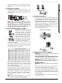
2.12 Bell Output Wiring (BELL+ and BELL-)
These terminals are used for powering
bells, sirens or other devices requiring
steady output voltage on alarm. The
panel can provide up to 2A short-term
or 700mA long-term current. The output is supervised. A trouble condition
will be generated when the bell connection is lost. If no bell or siren is
being used, connect a 1000Ω resistor
across the BELL+ and BELL- terminals
to eliminate a trouble condition.
To ensure proper operation, the wire length of the bell
loop must be considered.
Consult the following chart to determine the maximum
wire length for the bell loop with respect to current. The
values reflect the use of a 30 watt siren.
The cabinet should be earth grounded using the grounding kit supplied. Ensure that the connection from the cabinet to the metallic cold water pipe or earth grounding rod
is made with minimum 14-gauge solid copper wire.
The EGND terminal must be connected to earth ground to
enable ground fault detection. A Ground Fault trouble
will be indicated if any conductor on the system has a
resistance to earth ground of 40kΩ or less.
Only earth ground the main panel and the first module
connected to the telephone line.
Tighten nut to break paint and make
good connection to the cabinet
Distance to last bell/siren (ft/m)
Bell Loop
22 AWG 20 AWG 18 AWG 16 AWG
Load
Wire
Wire
Wire
Wire
Current
14 AWG
Wire
2000mA
18/6
29/9
46/14
73/22
116/35
1800mA
20/6
32/10
51/16
81/25
129/39
1000mA
36/11
58/17
92/28
147/44
233/70
700mA
52/16
82/25
132/40
210/64
332/101
73/22
115/35
184/56
293/89
500mA
100mA
364/110 577/175 922/279 1467/445
465/141
2326/705
To increase the length, double up on wire. For example,
when using 22-gauge quad, use two conductors for the
Bell+ connection and two for the Bell-. This effectively
doubles the maximum distance.
For UL residential installations, when a bell or siren is
used for fire signaling with a pulsed cadence, it must be
connected between the AUX+ and BELL- terminals. To
maintain bell circuit supervision, do not connect more
than one device to the BELL- terminal. A fire bell or siren
used for this application must be UL Listed and have a
current consumption of 400mA or less (e.g. Wheelock
MT-12/24-R).
NOTE: For Commercial Fire applications, you must use
the ‘CF’ version of the panel and the PC4702BP.
2.14 Applying Power (AC and Battery)
WARNING: Do not connect the battery or transformer
until all other wiring is complete.
Battery Connection – Red & Black Battery Leads
Connect the red battery lead to the positive terminal of the
battery and the black lead to the negative terminal.
WARNING: Observe the correct polarity. If the battery
is connected backwards, the panel will not operate.
AC Power Terminals
WARNING: Connect the battery before connecting the
AC.
A 16V, 40 VA transformer connected to an unswitched AC
power source should be wired to these terminals.
To achieve the rated outputs as previously described, the
AC input must be connected to the secondary of a transformer rated at 16 VAC, 40VA minimum. The transformer
is not supplied with the equipment and must be mounted
outside the cabinet.
Do not connect the transformer primary to an outlet that is
controlled by a switch.
7
S EC T I O N 1 2 3 4 5 6 7 8 9 1 0 1 1 1 2 13 14 1 5 1 6
Typically, this output is used for providing power to latching type devices that require a power interruption in order
to reset.
The control panel monitors the presence of AC. Upon the
loss of AC power a trouble condition will be generated.
The keypad trouble light will turn on. If programmed, the
keypad will also beep. For more information regarding AC
options, see 10.1 ‘AC/DC Power Options‘.
Applying Power to the Main Panel
Once all field wiring has been completed and checked for
opens, shorts and grounds, power can be applied to the
panel as follows:
1. Connect the battery leads.
2. Connect the AC transformer.
The panel will not power up correctly if AC power is
applied before the battery is connected.
Battery Selection Charts
The charts below are to determine the battery required to
support the main panel for either 24 hours or 60 hours in
the standby mode. The battery size is measured in amp
hours (Ah). To determine the appropriate battery size, perform the following:
1. Calculate the total current required when the panel is
not in alarm. This is the standby current. See section
2.4 for further information on current calculation.
2. Determine the current that will be drawn when the
panel is in alarm.
3. On the chart below, find the standby current on the horizontal axis and the alarm current on the vertical axis.
4. Find the region of the chart where the standby current
and the alarm current values intersect. The region corresponds to the required battery Ah capacity.
For example:
Standby current = 500 mA
Alarm current = 2 A
On the 24Hr chart, the battery capacity required is 14Ah.
8
2.15 Lithium Batteries
The PC4020 circuit board includes a lithium battery
(please see the wiring diagram on page ii.) This battery is
not replaceable. There is a danger of explosion if the battery is incorrectly replaced.
If the lithium battery stops working, return the circuit
board to your distributor. Batteries may cause a fire when
in contact with metal. If you need to dispose of the circuit
board and/or the lithium battery, wrap the battery in nonconductive tape. Check with your local government for
battery disposal regulations.
WARNING: Do not store the batteries in such a way
that they come into contact with each other or with any
piece of metal. Explosion or fire may occur. Should fire
occur, use only dry chemical fire extinguishers. Do not
use water to put out the fire.
Do not heat the batteries. Do not dispose of the batteries or circuit boards in a fire. Do not disassemble the
batteries. Do not apply pressure to or deform the batteries. Ensure that the above precautions are strictly
observed by related departments, including, but not
limited to, production, sales and outside contractors.
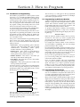
Section 3: How to Program
3.1 Introduction to Programming
The PC4020 is programmed via a menu system. Use the
arrow keys (<>) to scroll through different menu options
and press the [*] key to select the menu option displayed.
Continue this procedure until the required program section is displayed, then press the [*] key to select it. To
arrive at a program section where data can be entered
may require scrolling and selecting items from several
menus. Press the [#] to return to the previous menu.
To enter Installer’s Programming, enter [*][8][Installer’s
Code] at any keypad that is enrolled on the system.
In order to prevent unauthorized personnel from accessing Installer’s Programming, the Installer’s Code should
be changed from the default setting. By default, the
Installer’s Code is [5555]. To change the Installer’s Code,
see 7.1 ‘Installer’s Code‘.
Once you have entered Installer’s Programming, the first
menu consists of five items, listed below. Use the arrow
keys (<>) to scroll to the desired menu item and press the
[*] key to select it:
• System Area - These programming options affect the
operation of the entire system. These options include
communications, downloading, printer options,
installer and master code programming, etc.
• Partition Area - These options are programmed for
each partition. These options include zone assignments, partition times, partition options etc.
• Module Hardware - This menu is used when you
enroll the system modules and keypads.
• Event Buffer - This menu allows access to the system’s
event buffer for printing.
• Diagnostics - These options pertain to trouble conditions reported by the modules.
Use the arrow keys to scroll to the message indicating the
area you wish to program and press [*]. For example, to
program the Partition 2 account number, scroll to each of
the following messages and press [*]:
Scroll to...
Scroll to...
PARTITION AREA
<>
(01)
Press [*]
ADD/EDIT PAR
<>
(01)
Press [*]
PARTITION 2
<>
(02)
Press [*]
PARTITION ACCT #
<>
(00)
Press [*].
The arrow keys (<>) will appear in the top right-hand
corner of the display to indicate that there are multiple
menu items or program sections.
3.2 Programming by Reference Number
A quicker method of programming the panel is to jump
directly to a program section using the reference number
system. These reference numbers appear beside each
programming item in the Programming Worksheets, and
under each heading in the Installation Manual.
To program using reference numbers, enter Installer’s
programming([*][8][Installer’s Code]). Press and hold
the [A]uxiliary key until the keypad displays the following message:
’Enter Ref # then *’.
Enter the reference number found in the Programming
Worksheets for the section you wish to program, then
press the [*] key. The display will immediately go to the
programming item you have selected.
For example, the reference number for the Partition 2
Account Number is [0100XX00]. The ’XX’ is the 2-digit
partition number, in this case [02].
Once the Reference Number is entered and the [*] key is
pressed, the keypad will jump directly to that programming item. If an error is made when entering the reference number, use the [<] key to move the cursor back to
the first digit and re-enter the reference number.
Once you have programmed the section, you must press
[#] to save the change. Then, press and hold the [A] key to
enter another reference number.
Once you become familiar with each programming
option’s reference number, programming will become
quick and simple. If you forget a particular reference
number, you can always scroll through the menu items
in order to refresh your memory. All programming reference numbers are listed in the Programming Worksheets.
3.3 Programming Decimal Data
Some programming sections require decimal (0-9) entries,
such as zone definitions and system times. Make sure to
record all required decimal data in the Programming Worksheets before beginning to program each section.
Many sections require a specific number of digits. Once all
digits have been entered, the control panel will automatically exit that section and will return to the previous menu.
If the [#] key is pressed, only the data entered will be
changed. All programming data remaining will be left
unchanged. For example, when programming telephone
numbers, press the [#] key after the number is entered to
exit the programming item and to save having to program
all 32 digits.
Enter the 4-digit Partition 2 customer ID code. The display will return to the ’Customer ID Code’ display.
Press [#] to return to the previous menus and to exit the
installer programming mode.
9
3.4 Programming Hexadecimal Data
Hexadecimal or ’Hex’ digits are often required for a programming item, such as telephone numbers and reporting
codes. To insert a Hex digit into a given entry, press the [*]
key to enter the Hex menu. Use the arrow keys to scroll
through the each Hex digits (A through F). When the
desired letter is displayed, press the [*] key.
Hex digits can also be entered by pressing [*] key followed
by the number from 1-6 corresponding to each Hex letter
(A = 1, B = 2, C = 3, up to F = 6). Once the digit is entered,
the control panel will automatically return to the decimal
programming mode.
For example, to enter data ‘ABCD’ on a PC4020 you
would enter: [*], [1], [*], [2], [*], [3], [*], [4]
3.5 Programming Toggle Options
Many programming items are toggle options that are
either enabled or disabled. Use the arrow keys (< >) to
scroll through the toggle options. Press the [*] key to
switch back and forth between [Y]es (enabled) and [N]o
(disabled). Once all the toggle options have been programmed, press the [#] key to save your changes and
return to the previous menu.
10
Section 4: Module Enrollment
4.1 Enrolling Keypads and Modules
Once the wiring of all keypads and modules is complete,
they must be enrolled on the system. Apply power to the
system by first connecting the battery, followed by the AC
transformer. All LCD keypads will display the software
version of the keypad.
NOTE: Make sure all power to the system is OFF when
connecting modules.
NOTE: Record the location and number of each module
for future reference.
Enrolling the First Keypad to Partition 1
To enroll the first keypad, go to the keypad that is to be
assigned to Partition 1. Press any key on that keypad. The
keypad will beep and display the message ’45XX Mod. #1’.
This keypad will automatically be assigned to Partition 1.
Once the first keypad has been enrolled, the rest of the system keypads and modules can be enrolled through the
’Module Hardware’ section of installer’s programming.
Enrolling All Other Keypads and Modules
Ref # [0200] then scroll to desired module
Enter the following at the keypad you have just enrolled:
1. Enter installer’s programming by pressing [*] [8]
[Installer’s Code].
NOTE: The default installer’s code is [5555].
2. Scroll to ’Module Hardware’ and press the [*] key.
3. The message ’Enroll Module’ will appear. Press [*].
4. Scroll through the different modules until the module
you wish to enroll is displayed. Press the [*] key.
LCD45XX Keypads
The keypad will display the message ’Press Any Key On
Desired Unit’. Go to the keypad to be enrolled and press
any key. Return to the original keypad. A message similar
to the following will be displayed to confirm enrollment
(e.g. ’LCD45XX Mod 02 Enrolled’).
For keypads: next, you must select which partition the
keypad is to control. Use the arrow keys to scroll to the
desired partition and press the [*] key to select. If the
enrolled keypad is slated for global operation, scroll to
Option 00 ’Global’ and press [*].
If you press the [#] key, the keypad will be assigned to Partition 1 by default.
For more information regarding partition and global keypads, see Section 6: ‘Keypad Operation‘.
Module Tampers
When enrolling PC4108A, PC4116, PC4204/PC4204CX,
PC4216, PC44XX, PC4702, PC4820, PC4850, PC4164 or
alternate communicator modules, the message ’Create
Tamper On Desired Unit’ will be displayed. The tamper is
required for enrollment.
To create the required tamper, secure the tamper zone on
the module and then open it. It is this transition from
secure to violated which enrolls the module. After this is
done, the keypad will display the module number and
will confirm enrollment (e.g. ’PC4204/PC4204CX Mod 01
Enrolled’). Record the module number in the programming worksheets. Once the module is enrolled, re-secure
the tamper.
Zone Expanders
NOTE: Enroll all zone expanders before assigning zones
to PC4820 and AML devices.
When enrolling zone expanders (PC4108A, PC4116 and
PC4164), the panel will display ’PC41XX Module’. It does
not ask what type of expander is being enrolled. Once the
tamper is created, the control panel will automatically indicate the type of expander and will confirm enrollment (e.g.
’PC4116 Mod 01 Enrolled’).
Zones 1 to 16 are located on the main control panel. Additional zones are added in sequence. For example, if two
PC4108A zone expanders are enrolled, the first one enrolled
will be assigned zones 17 to 24 and the second will be
assigned zones 25 to 32.
The system can have a maximum of 128 zones. To confirm
which zones are assigned to which expander, press any key
when the enrollment confirmation message is displayed.
NOTE: Be sure to record the zones assigned to each
zone expander module in the System Overview section
of the Programming Worksheets.
The PC4164 is a wireless receiver. When you enroll a
PC4164 module, you can enroll up to 64 wireless devices on
the system.
You can enroll up to eight PC4164 wireless receivers. This
will give you a greater range in which to install wireless
devices. It will also allow you to install backup wireless
receivers with overlapping ranges, to provide increased
security for the wireless zones on the system.
NOTE: The maximum number of wireless zones you can
enroll on the system is 64, even if you install more than
one PC4164 wireless receiver.
ESCORT4580, PC4701 and PC4936 Enrollment
When enrolling the ESCORT4580, the PC4701 or the
PC4936, the keypad will display the message ’Looking for
PC4XXX Module’. The panel will automatically scan the
Combus for the module. Once it is found, the panel will
confirm enrollment (e.g. ’ESCORT4580 Module Enrolled’).
No tamper is required.
4.2 Deleting Modules
Ref # [0201] then scroll to desired module
Sometimes, a module must be deleted from the system.
This could be when zone expanders are enrolled out of
sequence or if a module is defective.
To delete a module, enter the following at any enrolled
keypad:
1. Enter installer’s programming by pressing [*] [8]
[Installer’s Code].
2. Enter reference number [0201] then press [*].
3. Scroll through the different modules until the module
you wish to enroll is displayed. Press [*] to select.
4. Scroll to the correct module type, then to the correct
module number. For example, to delete LCD45XX
Module 04, scroll to ’LCD45XX (04)’. Press the [*] key
to delete the module.
NOTE: When deleting and/or replacing zone expanders, all remaining zone expanders should be reenrolled. This will ensure proper zone assignment and
operation.
11
4.3 Confirming Modules
Ref # [0202] then scroll to desired module
In case module numbers were not recorded, you can verify this information through the ’Confirm Module’ menu
in the ’Module Hardware’ programming section in
installer’s programming.
This works just like enrolling modules. You will be
prompted to ’Press Any Key On Desired Unit’ in the case of
keypads and ’Create Tamper on Desired Unit’ in the case of
modules. Once the correct action is taken, the keypad will
display the module number (e.g. LCD45XX Mod 02).
4.4 Enrolling AML Devices
Addressable Multiplex Loop (AML) devices use a 2-wire
connection for power and communication to and from the
control panel. All detectors are designed for low power
consumption to make for an efficient system.
For information on AML wiring, please see 2.9 ‘AML
Device Wiring‘.
Enroll the AML devices after all PC4108A, PC4164 and
PC4116 modules have been enrolled.
Programming the PGM Terminal for an AML Loop
Ref #: [001400]
To enroll addressable multiplex loop (AML) devices, you
must first program the PGM terminal you have selected
for the loop. Perform the following:
1. Enter Installer’s Programming and enter reference
number [001400].
2. To select PGM1 for AML devices, scroll to ’PGM1
AML?’ and press [*]. The option will toggle to Yes.
3. To select PGM2 for AML devices, scroll to ’PGM2
AML?’ and press [*]. The option will toggle to Yes.
NOTE: Do not turn off the PGM AML toggle option
unless all AML devices have been removed from the
loop (see ’Removing AML Devices’).
To Enroll an AML Device
Ref #: [00140300] for PGM1
Ref #: [00140400] for PGM2
NOTE: All AML devices must be connected before they
are enrolled.
To enroll the device, perform the following:
1. FOR DEVICES TO BE ENROLLED ON PGM1: Enter
Installer’s Programming and enter reference number
[00140300].
FOR DEVICES TO BE ENROLLED ON PGM2: Enter
Installer’s Programming and enter reference number
[00140400].
2. Enter the 5-digit serial number on the detector to be
enrolled.
3. If the correct serial number was entered, the panel will
allow you to select the zone that the addressable detector
will be assigned to. Any zone from zone 001 to 128 on
the PC4020 v3.3 can be used as an AML zone. If the
detector is not connected to the PGM terminal, the zone
will not be enrolled. Do not use zones designated for Access
Control.
Repeat from Step 2 until all AML devices have been enrolled.
If the zone serial number is already programmed into the
panel, the panel will display the message ’Already
Enrolled’ on the top line of the LCD and the serial number
on the bottom line of the LCD for three seconds. The panel
will then display the zone assignment for the device. This
allows for the reassignment of an existing zone or to verify
programming.
12
NOTE: Only the AMS-220/220T devices may be defined
as fire zones. Do not program other AML devices as fire
zones.
AML Key
Ref #: [001401]
IMPORTANT NOTE: To ensure system security, the
AML Key must be programmed when using AML
devices.
The AML Key is a 2-digit code that acts as a security lock
for the AML detectors. Once you have enrolled all AML
zones, you must change the AML Key from [00] to
another 2-digit number (01-FF). When the AML Key is
changed, the panel broadcasts the new code to each
addressable device. Any device added to the system with
a AML Key other than the one programmed or the default
[00] will not function.
When an addressable device is deleted, the panel reprograms the device’s AML Key to 00. This allows the device
to be re-enrolled on another system.
Moving AML Devices
To another zone on the same loop
1. FOR DEVICES TO BE MOVED ON PGM1: Enter
Installer’s Programming and enter reference number
[00140300].
FOR DEVICES TO BE MOVED ON PGM2: Enter
Installer’s Programming and enter reference number
[00140400].
2. Enter the device’s 5-digit serial number. The keypad
display will read ’Already Enrolled [serial number]’ to
indicate that the device has already been enrolled.
3. After three seconds, the display will indicate the
device’s zone assignment. Enter the new zone number. Any zone from zone 001 to 128 on the PC4020
v3.3 can be used as a AML zone.
4. The zone definition and attributes must also be programmed for the new zone.
To another zone on a different loop
When moving devices to another loop, they must be
deleted from the first loop by following the instructions in
’Removing AML Devices’ (see below). The device’s serial
number can then be re-entered on the other loop as indicated in ’To Enroll an AML Device’ (see above).
Removing AML Devices
Ref #: [00140301] for PGM1
Ref #: [00140401] for PGM2
When removing AML devices, they must be deleted from
the loop. If the device is not deleted, its AML Key will not
be reset to [00].
To remove an AML device from the system, perform the
following:
1. For devices to be deleted from PGM1: Enter
Installer’s Programming and enter ref# [00140301].
For devices to be deleted from PGM2: Enter
Installer’s Programming and enter ref# [00140401].
2. The display will read ’Serial# [ ]’ on the top line of
the display and the zone label on the bottom line of
the display. Use the [<][>] keys to scroll to the zone to
be deleted then press [*]. The bottom line of the display will then read ’Zone Deleted’.
3. To delete all AML devices from the selected PGM
output, select Default AML. The panel will display
’Confirm Default Press [*]’. To delete all AML devices
on the selected PGM, press [*].
Section 5: Partitions and Zones
5.1 Zone Supervision
Ref # [000204] ’Zone Supervision’
The control panel must be instructed to supervise either
No End of Line, Single EOL or Double EOL zone loops.
These three options are described in Section 2.5 ’Zone Wiring’.
To program this option, perform the following:
1. Enter installer’s programming by pressing [*] [8]
[Installer’s Code].
2. Enter reference number [000204] and press [*].
3. Scroll through the three supervision types. Press [*] to
select the supervision type you require.
5.2 Creating Partitions
Once all system wiring has been completed and you have
enrolled your keypads and modules, you can begin programming partitions. This will include indicating the
number of partitions and programming the available
options for each. Partitions must be programmed individually.
NOTE: If you do not wish to use partitions, you must
assign all zones which will be used to Partition 1 (see 5.3
‘Adding Zones to Partitions‘).
There are five basic programming items for each partition:
1. Programming the partition account number.
2. Programming the partition toggle options.
3. Programming the partition times (entry and exit
delay times, etc.).
4. Adding zones to the partition and defining each zone
(zone label, zone type and attributes).
5. Programming the partition label.
Partition Account Number
Ref #: [0100XX00] where XX = partition number
Enter a 4 or 6-digit partition account number. Partitions can
all report using the same account number, or each can be
programmed differently depending on your application.
Enter the four or six digits and record them into your Programming Worksheets. Once you have entered all the digits,
the display will return to the ’Partition Acct #’ prompt..
Partition Toggle Options
Ref #: [0100XX01] where XX = partition number
There are numerous partition options which can be either
enabled (select ’Y’ for yes) or disabled (select ’N’ for no).
Pressing [*] will toggle between the yes and no options.
The following partition toggle options generally pertain to
the operation of the keypads, the entry and exit delay
options and the end user feature accessibility for the
selected partition. These features are explained in detail in
other sections of the manual. Below is a list of the available
options followed by their default. Each option is described
later in this manual in the specified sections.
[F] Enabled (Y) ........................ see section 6.5 on page 19
[A] Enabled (Y) ....................... see section 6.5 on page 19
[P] Enabled (Y) ........................ see section 6.5 on page 19
Display Clock (Y).................... see section 6.1 on page 18
Clock Armed (N) .................... see section 6.1 on page 18
Disp Exit Time (Y)................... see section 6.1 on page 18
Bypas Req Code (Y) ................see section 7.9 on page 26
AutoArm/Disarm (Y) ............see section 8.2 on page 27
Autoarm Req Code (N) ..........see section 8.2 on page 27
Autoarm Squawk (N).............see section 8.2 on page 27
Bell Squawk (N) ......................see section 8.1 on page 27
Keypad Lockout? (N) .............see section 6.6 on page 19
Cmd. OutX Req Cd (N)..........see section 7.9 on page 26
[*][6] Any Cd (N).....................see section 7.9 on page 26
Exit Delay Aud (N) .................see section 9.2 on page 28
Exit Delay Sqk. (N) .................see section 9.2 on page 28
Aud. Exit Fault (N) .................see section 8.1 on page 27
Entry Urgency (N) ..................see section 9.2 on page 28
Entry Squawk (N) ...................see section 9.2 on page 28
Exit Del. Term (N) ...................see section 9.2 on page 28
System Alarms (N) .................see section 6.1 on page 18
System Status (N)....................see section 6.1 on page 18
Sen. Rst. Cmd#2 (Y) .............. see section 11.3 on page 33
Spcl Alm Entry (Y)..................see section 9.2 on page 28
Exit Tbl Beep (N) ....................see section 9.2 on page 28
Partition Times
Ref #: [0100XX02] where XX = partition number
There are eight different partition times to be programmed. See the corresponding section for further information regarding each timer:
• Entry Delay – section 9.1 ‘Entry and Exit Delay Times‘
• Exit Delay – section 9.1 ‘Entry and Exit Delay Times‘
• Auxiliary Entry Delay – section 9.1 ‘Entry and Exit
Delay Times‘
• Auxiliary Exit Delay – section 9.1 ‘Entry and Exit
Delay Times‘
• Delinquency – a Closing Delinquency reporting code
will be sent if the partition is not armed for the number
of days programmed in this section.
• Autoarm Pre-alert – section 8.2 ‘Automatic Arming‘
• Quick Bypass Duration - ‘24Hr Quick Bypass (24)‘
• Quick Bypass Pre-alert - ‘24Hr Quick Bypass (24)‘
Three digits are required for each entry.
Zone Assignment
Ref #: [0100XX03] where XX = partition number
This procedure is outlined in Section 5.3 ’Adding Zones to
Partitions’.
Partition Labels
Ref #: [0100XX04] where XX = partition number
Program partition labels in this section. All system display
labels are programmed in a similar fashion. For instructions on programming labels, see 5.4 ‘Zone Programming‘.
Deleting Partitions
Ref #: [0101]
Scroll to the partition to be deleted, then press [*]. When a
partition is deleted, the programming assigned to it will
not be erased. If the partition is re-enabled, the programming that was entered will still be there.
13
NOTE: When a partition is deleted, the zones assigned
to it are removed from the Zone Assignment.
Copying Partitions
Ref #: [0102]
Enter this section to copy the programming from one partition to another one. The programming that will be copied includes the Customer ID Code, Partition Toggles,
Partition Times, Access Code Levels and Command Output Labels. The zone assignment will not be copied. To
copy a partition:
1. The panel will prompt ’From Which Partition’. Scroll
to the partition you want to copy programming from.
Press [*].
2. The panel will prompt ’To Which Partition’. Scroll to
the partition you want to copy programming to.
Press [*].
Both partitions now have the same programming.
5.3 Adding Zones to Partitions
Add New Zone
Ref #: [0100XX0300] where XX = partition number
Zones must be assigned to partitions in order for them to
operate. By default, the first 16 zones on the control panel
are assigned to Partition 1. When you select this menu
item, the panel will display the first zone not assigned to
the partition. Use the arrow keys (<>) to scroll through the
zones not assigned to the partition. When the zone to be
added is displayed, press the [*] key to select it.
Once you have selected the zone to add, there are three
items to be programmed:
1. Zone Label: this 14-character label will appear on the
LCD display of the keypad.
2. Zone Type: this determines how the zone will operate.
3. Zone Attributes: these attributes are toggled on and
off and affect how the zone will function.
For instructions on programming these items, see 5.4
‘Zone Programming‘.
Press [#] once you have finished programming a zone. The
keypad will display the next available zone to be added.
Global Zones
If a given zone is added to more than one partition, it
becomes a global zone. A global zone differs from single
partition zones in the following ways:
• A global zone will not be armed until all partitions to
which the zone is assigned are armed.
• A global Delay type zone will follow the longest programmed delay time of the partitions it is assigned to.
• A global Stay/Away type zone will not be activated
until all partitions the zone is assigned to are armed in
the Away mode, or the interior has been activated by
pressing [*] [1].
• When a global zone is manually bypassed, as soon as
any partition the zone is assigned to is disarmed, the
zone will no longer be bypassed.
Edit Zone
Ref #: [0100XX0301] where XX = partition number
When you select this menu item, the panel will display the
first zone assigned to the partition. Use the arrow keys
(<>) to scroll through the zones assigned to the partition.
When the zone to be edited is displayed, press the [*] key
to select it.
14
Adding and editing zones follow the same menu system.
All options for editing a zone are described in Section 5.4
’Zone Programming’.
Delete Zone
Ref #: [0100XX0302] where XX = partition number
When you select this menu item, the panel will display the
first zone assigned to the partition. Use the arrow keys
(<>) to scroll through the zones assigned to the partition.
When the zone to be deleted is displayed, press the [*] key
to delete it. Press the [#] key to exit once all zones not
required for the partition have been deleted.
5.4 Zone Programming
Ref #: [0100XX0301YYY] where XX = partition number
and YYY = zone number
Once a zone has been added to a partition, you must program the following:
• zone label
• zone type
• zone attributes
To program the zone, enter the reference number indicated above. Press [*] to select the zone. The three programming items are accessible from the zone
programming menu.
Zone Labels
When the zone label programming option is selected, the
panel will display the presently programmed label
(default ’Zone XXX’). Follow the instructions below to
program the label.
Programming System Labels
A cursor will appear under the first letter of the default
label. Move the cursor to left or right by pressing the
arrow (< >) keys. The letters of the alphabet have been
divided up among the number keys 1 to 9 on the keypad
as follows:
[1] = A, B, C, 1
[2] = D, E, F, 2
[3] = G, H, I, 3
[4] = J, K, L, 4
[5] = M, N, O, 5
[6] = P, Q, R, 6
[7] = S, T, U, 7
[8] = V, W, X, 8
[9] = Y, Z, 9, 0
[0] = Space
For example, if you press the [4] key once, the letter ’J’ will
appear above the cursor on the display. Press the [4] key
again, the next letter ’K’ will appear, and so on. If a different number key is pressed, the cursor will automatically
move to the right one space. To erase a character, use the
arrow keys to move the cursor under the character, then
press the [0] key.
There are other options when programming labels. Press
the [*] key to call up the options menu. Scroll through the
options using the arrow (< >) keys, then press the [*] key
to select.
[0] Clear Display will clear the entire label.
[1] Clear to End will clear the display from the character
above the cursor to the end of the display.
[2] Change Case will toggle between uppercase and
lowercase letters.
[3] ASCII Entry is for entering uncommon characters.
Use the arrow (< >) keys to toggle through the characters or enter a 3-digit number from 032 to 255. Press
the [*] key to enter the character. See Appendix D at
the back of this manual for a list of the available
ASCII characters.
[4] Cancel and Exit will exit zone label programming.
No changes will be saved.
P a r t i t i o n s
Zone Types
The following is a description of each zone type:
Standard Delay (00)
Standard Delay zones have an entry and exit delay. The
exit delay will begin as soon as arming is initiated. The
delay zone may be opened and closed during the delay
time without causing an alarm. After the exit delay time
has expired, the zone is armed. Opening the zone will
start the entry delay. If the panel is disarmed before the
entry time expires, no alarm will be generated.
Auxiliary Delay (01)
The Auxiliary Delay zone operates the same way as the
Delay zone, except different entry and exit delay times can
be programmed: Auxiliary Entry and Auxiliary Exit
Delay. Having a second delay zone provides greater flexibility for areas which require more time to arm and disarm the system.
Instant (02)
An Instant zone will be armed when the exit delay
expires. Violating this zone when armed will cause an
instant alarm.
Interior (03)
An Interior zone will be armed when the exit delay
expires. If a Delay zone is violated first, this zone will wait
for the Delay time before going into alarm. If this zone is
violated first, it will create an instant alarm.
Interior Delay (04)
When the partition is armed in the Away mode (interior
zones active), this zone will operate as an Interior zone.
When the partition is armed in the Stay mode (interior
zones bypassed), this zone will operate as a delay zone.
Interior Stay/Away (05)
This zone acts as an interior zone. The zone will be automatically bypassed if no delay zone on the partition is violated during the exit delay or if the partition is armed in
the Stay mode.
Delay Stay/Away (06)
This zone will operate the same as the Delay zone with
one exception: this zone will be automatically bypassed if
the partition is armed in the Stay mode.
Standard Fire (07)
When a Standard Fire zone goes into alarm, the panel will
activate all fire outputs and will immediately transmit a
reporting code to the central station, if programmed. The
fire output can be programmed to pulse—two seconds on,
two seconds off—or to follow one of the other fire bell patterns (see 11.3 ‘Programmable Output Options‘, options
49-53). If an open condition is present, the panel will
immediately display and communicate a trouble condition. All keypads will annunciate the trouble by activating
the Trouble light and beeping twice every ten seconds.
The keypads can be silenced by pressing any key.
NOTE: Fire zones always require single EOL resistors
regardless of any other programming. Never program a
fire zone as silent. Refer to the wiring diagram or Section 2.9 ’Zone Wiring’ for fire zone configuration.
Delayed Fire (08)
This fire zone works the same way as a Standard Fire zone
except that the alarm memory and communication are
delayed by 30 seconds. The fire outputs are activated
Z o n e s
immediately. The alarm can be acknowledged by the user
by pressing any key before the 30-second delay expires.
If the alarm is acknowledged, the panel will silence the
alarm and delay communication of the signal for 90 seconds to allow the user a chance to correct the problem. If
the Delayed Fire zone is still in alarm 90 seconds later, the
panel will again activate the fire output and delay communication for 30 seconds, at which point the user can
acknowledge the alarm again.
If the alarm is not acknowledged, the panel will latch the
alarm after the 30-second delay and will communicate to
the central station.
NOTE: Fire zones always require single EOL resistors
regardless of any other programming. Never program a
fire zone as silent. Refer to the wiring diagram or Section 2.9 ’Zone Wiring’ for fire zone configuration.
Auto Verifying Fire (09)
Auto verify Fire zones operate similar to Standard Fire
zones. When the zone goes into alarm, the panel will perform a sensor reset for 20 seconds and then will wait 10
seconds for the detectors to clear. If the same zone goes
into alarm within 60 seconds, the panel will immediately
activate the fire outputs and will communicate to the central station, if programmed.
NOTE: In order for this zone to operate, the smoke
detector power supply must be connected to an output
programmed as Command Output #2.
NOTE: Fire zones always require single EOL resistors
regardless of the programmed zone supervision. Never
program a fire zone as silent. Refer to the wiring diagram or Section 2.9 ’Zone Wiring’ for fire zone configuration.
Waterflow (10)
When an alarm occurs, the fire outputs will activate. If
programmed, the panel will immediately send a Waterflow Alarm reporting code to the central station. The
Waterflow zone will also follow the Waterflow delay, if
programmed (see 10.9 ‘Transmission Delay‘).
NOTE: Waterflow zones always require single EOL resistors regardless of any other programming. Refer to the
wiring diagram or Section 2.9 ’Zone Wiring’ for zone
configuration.
Fire Supervisory (11)
A Fire Supervisory zone monitors fire critical systems to
indicate when those systems are in a condition that could
prevent normal operation. This zone will indicate an ’OffNormal Supervisory’ condition when a short circuit is
detected. When the zone is open, a zone trouble will be
indicated and the keypad will beep. This zone will not
activate the verbal alarm feature on the PC4936.
24 Hour Zones (Types 12-23)
These zones are always active. When violated, they will
create an alarm, whether the partition is armed or disarmed.
For Types 16-21: When violated, the panel will immediately latch the bell outputs and will communicate to the
central station. Each zone has a different SIA identifier.
• 24 Hr Bell (12): This zone, when violated, will activate
the burglary outputs. This zone will not activate the
verbal alarm feature on the PC4936.
• 24 Hr Bell/Buzzer (13): This zone, when violated, will
create an alarm whether the partition is armed or disarmed. However, if the panel is armed, it will activate
15
S EC T I O N 1 2 3 4 5 6 7 8 9 1 0 1 1 1 2 13 14 1 5 1 6
[5] Save will save any changes and exit zone label programming.
a n d
•
•
•
•
•
•
•
•
•
•
the burglary outputs; if disarmed it will activate the
keypad buzzer. When the partition is disarmed, this
zone will not activate the verbal alarm feature on the
PC4936.
24 Hr Buzzer (14): This zone, when violated, will activate the keypad buzzer.
24 Hr Technical (15): This zone is silent.
24 Hr Gas (16): This zone is audible.
24 Hr Heat (17): This zone is pulsed audible.
24 Hr Medical (18): This zone is silent.
24 Hr Emergency (19): This zone is audible.
24 Hr Water (20): This zone is audible.
24 Hr Freeze (21): This zone is audible.
24 Hr Holdup (22): This zone is silent. It does not activate Burglary outputs or the Latched Strobe output.
24 Hr Panic (23): This zone is silent. It does not activate
Burglary outputs or the Latched Strobe output.
24Hr Quick Bypass (24)
Quick Bypass zones are armed at all times. Users can temporarily bypass all Quick Bypass zones on a partition by
either pressing the Quick Bypass function key, or entering
[*][6][access code][14].
NOTE: It is recommended that the Quick Bypass function key be used.
When a user enters the Quick Bypass command, the zone
will be bypassed for the amount of time that was programmed in the Quick Bypass Duration section.
If the zone is open when the Quick Bypass Duration timer
expires, the panel will begin the Quick Bypass Pre-alert.
During the pre-alert, the buzzers of all the keypads on the
partition will sound.
Users can silence the pre-alert and start the Quick Bypass
Duration timer by either entering the Quick Bypass command, or a valid access code.
The zone will be restored at the end of the Quick Bypass
Pre-alert time, if it has been closed. If the zone is still open
when the pre-alert time expires, the zone will go into
alarm. The panel will log the alarm to the event buffer and
will transmit the alarm (if programmed), but the alarm
will not be recorded in alarm memory ([*][3] command).
If another Quick Bypass zone is violated during the prealert sequence, both zones will go into alarm at the end of
the pre-alert period.
If the zone has been bypassed using the [*][1] menu, the
pre-alert will not be triggered and the zone will not go into
alarm when it is violated.
When you program any zone on a partition as 24Hr Quick
Bypass, you should also program these partition times:
Quick Bypass Duration
Ref#: [0100XX0206] where XX = Partition 01-08
Program the amount of time (seconds) that 24Hr Quick
Bypass zones on the partition will remain bypassed when
a user enters a quick bypass command.
Quick Bypass Pre-alert
Ref#: [0100XX0207] where XX = Partition 01-08
Program the amount of time (seconds) that the pre-alert
will sound when the zone is violated.
NOTE: If you assign a Quick Bypass zone to more than
one partition, then the quick bypass duration and prealert times must be the same on each of the partitions.
16
Latching 24 Hr (25)
When violated, this zone will operate the same as the 24
hour bell zone (12) with one exception: the installer’s
mode ([*][8]) must be entered before the system can be
armed. The keypad display will read ’Arming Inhibited
Call for Service’. This is to ensure that the problem will be
examined by the installer.
Momentary Arm (26)
A momentary closure of this zone will alternately arm and
disarm the partition. This zone can be used with a keyswitch to arm and disarm the system.
NOTE: This zone type must not be used as a global
zone. If a keyswitch zone has been tampered or
faulted, the zone must be restored before it can be
used to arm or disarm the system.
Maintained Arm (27)
When this zone is closed, the partition will disarm. When
this zone is violated, the partition will be armed. This
zone can be used with a keyswitch to arm and disarm the
system.
NOTE: This zone type must not be used as a global
zone. If a keyswitch zone has been tampered or
faulted, the zone must be restored before it can be
used to arm or disarm the system.
Forced Answer (28)
When this zone is tripped, the panel will instantly pick up
the telephone lines to search for a downloading computer.
Do not use this zone type to monitor for alarms.
LINKS Sup (29)
The LINKS Supervisory zone is used with a LINKS module to monitor for troubles. When the LINKS PGM output
activates, a LINKS trouble will be logged on the event
buffer and the zone trouble will be transmitted.
NOTE: LINKS Supervisory zones always require single
EOL resistors regardless of any other programming.
Refer to the wiring diagram or Section 2.6 ’Specialized
Zone Wiring’ for zone configuration.
LINKS Answer (30)
The panel can be uploaded/downloaded via the cellular
network. If the LINKS1000 detects an incoming call, it will
activate an output which can be used to violate this zone
type, forcing the panel to answer the cellular call and
begin communicating with the downloading computer.
NOTE: LINKS Answer zones always require single EOL
resistors regardless of any other programming. Refer to
the wiring diagram or Section 2.5 ’Zone Wiring’ for
zone configuration.
AC Delay (31)
When this zone is violated the panel will begin to count
the AC TX Delay time. When this time expires the panel
will transmit the General System Trouble event and
annunciate an AC Trouble on all partitions. When the
zone is restored the panel will again count the AC TX
Delay Time before restoring the trouble and transmitting
the General System Trouble Restore event.
NOTE: AC Delay zone always requires single EOL resistors regardless of any other programming. Refer to the
wiring diagram or Section 2.5 ’Zone Wiring’ for zone
configuration.
P a r t i t i o n s
Function Key Zone (33)
The Function Key Zone definition, when selected, causes
the panel to prompt the function key list and allow the
installer to select the following list of functions:
(00) Null Key
(01) Stay Arm
(02) Away Arm
(03) No-entry Arm
(04) Chime On/Off
(05) System Test
(06) Quick Exit
(07) Arm Interior
(08) Command O/P 1
(09) Command O/P 2
(10) Command O/P 3
(11) Command O/P 4
(12) Command O/P 5
(13) Command O/P 6
(14) Command O/P 7
(15) Command O/P 8
(16) Silence Trouble
(17) Silence Bells
(18) Fire Reset**
(19) Fire Drill
(20) Lamp Test
(21) Fire Insp Tst
(22) Quick Bypass
(23) Music Input
(24) Maid’s Code
(25) Cancel Key
When this zone is violated the panel will perform the
appropriate function for the partition to which the zone is
assigned. No access code is required. Tampers, Faults, or
Device Faults on the zone will not cause the panel to perform the respective function (even if Tamper/Fault Opens
Zone is enabled). The installer should ensure that the
method provided to activate this zone provides sufficient
security for the function being performed.
NOTE: The zone attributes of this zone type should
never be used. This zone type should not be programmed as global.
Zone Attributes
The following is a description of each zone option. Scroll
through each option and press [*] to toggle between on
and off. When all necessary changes are made, press [#] to
return to the previous menu.
Each zone type has different attributes enabled by default.
For a list of these default settings, see the Programming
Worksheets.
• Bell Audible – This will determine whether the zone
will activate bell outputs and PGM outputs programmed to sound fire/burglary alarms when an
alarm occurs. Select [Y] for audible, [N] for silent.
• Bell Pulsed – This will determine how the bell outputs
and PGM outputs programmed to sound fire/burglary
alarms will sound for an alarm. Select [Y] for pulsed,
[N] for steady.
• Bypass Enable – This will allow the zone to be manually bypassed. Select [Y] to allow bypassing by the
user, [N] to prevent it. This attribute should not be
enabled for Fire zones.
Z o n e s
• Chime Function – If the door chime option is enabled,
keypad will chime both when the zone is violated and
restored. Select [Y] for chime, [N] for no chime. To activate/deactivate the Door Chime feature for a partition,
enter [*][4] at a keypad.
• Force Arm – When force arming is enabled, the partition(s) the zone is assigned to can be armed even if the
zone is not secure. The zone will be temporarily
bypassed and will be added back into the system if it is
later restored. Select [Y] to enable this feature. If [N] is
selected, the zone must be secured or manually
bypassed before arming will be allowed.
• Swgr Shut Down – Swinger shutdown. After the zone
has reported the programmed number of alarms, the
zone will be shut down. Swinger shutdown is reset
every time the panel is armed, or when the clock
reaches midnight. See 10.5 ‘Swinger Shutdown‘.
Select [Y] to enable this feature. If [N] is selected, the
panel will always transmit when an alarm occurs.
• TX Delay – Transmission delay. When the zone goes
into alarm, the panel will sound the bell outputs
immediately but will delay communication to the central station for the programmed amount of time. If the
zone is disarmed before this time expires, no transmission is sent. If not, the panel will transmit the alarm
after the delay expires.
Select [Y] to enable this feature. If [N] is selected, the
panel will communicate immediately. To program the
Transmission Delay, see 10.9 ‘Transmission Delay‘
• Waterflow Del – This will enable the waterflow delay
for waterflow zones. Waterflow delay operates similar
to transmission delay except both the fire output and
communications will be delayed. If the zone is restored
before the programmable delay time, no transmission
is sent.
Select [Y] to enable this feature. If [N] is selected, the
panel will immediately activate the fire output and
communicate to central station.
• Non-Latch Toggle - Waterflow and Supervisory Zones
When the panel is used for pure supervisory/waterflow reporting - no alarm bells – the waterflow and
supervisory zone type is non-latching. When the panel
is used as a local fire panel and sounds local fire alarm
horns for evacuation, these zones types must be latching.
The following two options address these requirements:
Waterflow Latch, Fire Sup Latch.
Zone 1 Fast Loop Response
If the option Zone 1 Fast (ref # [000200]) is enabled, Zone 1
will have a loop response time of 32ms. If the option is disabled, Zone 1 will have a normal loop response time
(512ms). The option is disabled by default.
* Do not use in UL Listed installation.
** Use only in conjunction with a device UL Listed for fire.
17
S EC T I O N 1 2 3 4 5 6 7 8 9 1 0 1 1 1 2 13 14 1 5 1 6
Push To Set Zone Type (32)*
When a partition to which this zone is assigned is armed,
the exit delay for that partition will proceed normally until
the end of the exit delay is reached. At that time the exit
delay will continue to be annunciated but the partition
will not arm. To arm the partition the Push To Set Zone
must be violated and restored. Upon momentary violation
of this zone, any exit delay active for the partitions to
which the zone is assigned will be terminated.
NOTE: This zone type should not be programmed as
global.
a n d
Section 6: Keypad Operation
6.1 Partition Keypads
A partition keypad is a keypad that can access one partition. You can assign a keypad to a partition when you
enroll it (see 4.1 ‘Enrolling Keypads and Modules‘), or in
the Partition Assignment section (see below).
The partition keypad will primarily control the partition
to which it is assigned. However, a user will also be able to
control other partitions from the partition keypad, if that
user’s access code allows it.
When a user enters their code to disarm the partition at a
partition keypad, the partition to which the keypad is
assigned will disarm. The user will then have the option to
enter their code again to disarm the other partitions
enabled for their code.
Partition Assignment
To change the partition assignment of a keypad:
1. Enter reference number [0012XX00], where XX = the
keypad number.
2. Enter the number of the partition you want the keypad assigned to: (01) - (08), or (00) for Global assignment.
Partition Toggle Options
Partition keypads can be programmed to operate according to the following options. To program these toggle
options, enter reference number [0100XX01] where XX =
partition number. Press [✱] to toggle each option ON or
OFF. The programming will affect all keypads assigned to
the selected partition.
• Display Clock - If enabled, the partition keypad(s) will
display the time and date when not in use
(default=Yes).
• Display Clock While Stay Armed - If enabled, the
partition keypad(s) will display the time and date
when stay armed.
• Disp Exit Time - If enabled, the partition keypad(s)
will display the exit delay time during the exit delay
(default=Yes).
• System Alarms - If enabled, the partition keypad(s)
will display ’Partition X in Alarm’ and will beep (five
seconds on; five seconds off) when any other partition
is in alarm. This notification will end when the alarm is
cleared or when any key is pressed on the partition
keypad (default=No).
• System Status - If enabled, the partition keypad(s) will
display the status (Ready, Not ready, Armed, alarm
memory!, Force armed) of all active partitions on the
system. If disabled, the partition keypads will not display partition status. This option overrides the clock
display option (default=No).
The operation and functionality of the Fire, Auxiliary and
Panic keys are also programmable for partition keypads.
For more information regarding the FAP keys, see 6.6
‘Fire, Auxiliary and Panic Keys‘.
6.2 Global Keypads
Unlike a partition keypad, a global keypad is not assigned
to a single partition. Rather, a global keypad can be used
18
to access all partitions on the system. You can assign a keypad to be global when you enroll it (see 4.1 ‘Enrolling Keypads and Modules‘), or in the Partition Assignment
section (ref # [0015XX00]).
Global keypads should be placed in common or global
areas of the premises, such as points of entry/exit or
reception areas, where the ability to arm and disarm more
than one partition at a time is required.
When a user enters their code to disarm a partition at a
global keypad, the system will ask the user to select which
partitions they wish to disarm. The system will only allow
the user to disarm the partitions for which their access
code is enabled.
Global Keypad Options
Global keypads can be programmed to operate according
to the following options. To program these toggle options,
enter reference number [000200]. Press [✱] to toggle each
option ON or OFF. The programming will affect all global
keypads.
• Global Clock: If enabled, the time and date will be displayed on global keypads when they are not in use
(default=Yes).
• Global Trouble: If enabled, when a trouble condition
is present on the system, the trouble menu can be
viewed from global keypads. If disabled, global keypads will not list trouble conditions (default=Yes).
• Global Alarms: If enabled, the global keypads will
sound the buzzer and display the message ’[Partition
label] In Alarm’ when any partition is in alarm. The
keypad buzzer will be silenced and the message will
be cleared when the alarm has been restored or any
key is pressed on the keypad. If disabled, global keypads will not indicate alarms (default=No).
• Globl Sys Stat: If enabled, global keypads will display
the status (Ready, Not ready, Armed, alarm memory!,
Force armed) of all partitions on the system. If disabled, global keypads will not display partition status.
This option overrides the clock display option
(default=No).
• Global Entry: If enabled, global keypads will sound an
entry delay for all partitions. If disabled, the entry
delay will only be annunciated if all partitions are
armed (default=No).
The operation and functionality of the Fire, Auxiliary and
Panic keys are also programmable for global keypads. For
more information regarding the FAP keys, see 6.6 ‘Fire,
Auxiliary and Panic Keys‘.
6.3 Keypad Toggle Options
Entry / Exit Delay Tones
Ref #: [0012XX01], where XX = keypad number
You can turn off the entry and/or exit delay warning
tones for each keypad enrolled on the system. The entry/
exit delay tones are on by default.
Function Key Options
Ref #: [0012XX01], where XX = LCD45X1 keypad number
On each keypad, you can program each function key so
that users will need to enter an access code before the
panel performs the function. To do this, turn on the ’Funct.
X Code’ toggle option for that key. The default setting is
OFF for each key.
NOTE: Some function key types will require an access
code entry regardless of the programming in this section. See section 6.11 ‘Function Key Programming‘ for
more information.
6.4 Keypad Time-out
Ref #: [00020302]
Both global and partition keypads can be ’loaned’ to other
partitions on the system. When a user selects another partition, the keypad will display ’Accessing [Partition
Label]’ and will operate as a partition keypad from the
selected partition.
The amount of time that a loaned keypad will wait before
returning to its home partition (or, in the case of global
keypads, to its global mode) can be programmed. The
Keypad Time-out will begin after the last keypress is
made. To program the timer, enter reference number
[00020302]. Valid entries are from 020-255 seconds. Do not
program the Keypad Time-out for less than 020 seconds.
If your users will have access to audio help (using the
PC4936 and Escort4580 modules) you should increase the
Keypad Time-out setting to 60 seconds or more. This will
allow enough time for the system to announce the help
messages. The default setting is 020 seconds.
6.5 Keypad Blanking
Ref #: [000200]
When the Keypad Blanking toggle option is enabled, all
partition keypad lights – including the display – will turn
off. The keypad lights and display will remain off until a
key is pressed. If the Keypad Blanking Requires Code
option is enabled, the user will be required to enter their
access code in order for the keypad lights and display to
turn on.
To program these options, enter reference number
[000200] and scroll to the following items. Use the [*] to
toggle each option on or off.
• Kypd Blanking: Default = No
• Kypd Blnk Rq Cd: Default = No
6.6 Fire, Auxiliary and Panic Keys
By default, the Fire, Auxiliary and Panic keys are enabled
for both partition and global keypads. To send a fire, auxiliary or panic transmission, press and hold the corresponding [F], [A] or [P] keys for two seconds. FAP key alarms
will restore at the end of the Bell Cut-off time (see section
10.2 ‘Bell Circuit Supervision‘).
On an LCD4503 keypad, the Fire, Auxiliary and Panic
keys correspond to the Fire, Medical and Police buttons,
respectively.
On an LCD4501 keypad, the FAP keys are represented by
,
and . Press and hold both keys beside each symbol for two seconds to send the transmission.
Partition Keypad FAPs
Ref#: [0100XX01] where XX = partition number
• [F] Enabled: Default = Yes
• [A] Enabled: Default = Yes
• [P] Enabled: Default = Yes
To disable the [F], [A] or [P] keys on a partition keypad,
enter the appropriate reference number. Scroll to the cor-
rect options and press [*] to toggle each option ON or OFF.
The programming will affect all keypads assigned to the
selected partition.
NOTE: When a partition keypad is loaned to another
partition and a fire, auxiliary or panic key is pressed, the
fire, auxiliary or panic alarm will be transmitted using
the account number for the partition the keypad is
assigned to. The account number of the partition the
keypad is loaned to will not be sent.
Global Keypad FAPs
Ref#: [000200]
• Global [F] Key: Default = Yes
• Global [A] Key: Default = Yes
• Global [P] Key: Default = Yes
To disable the [F], [A] or [P] keys on a global keypad, enter
the reference number. Scroll to the correct options and
press [✱] to toggle each option ON or OFF.
Fire, Auxiliary and Panic Key Options
Ref #: [000201]
The operation of the Fire, Auxiliary and Panic keys can be
customized according to the following options. Each
option is individually programmable for the three keys.
To program these options, enter reference number
[000201]. Scroll to the following options and press [✱] to
toggle each option ON or OFF.
[F]/[A]/[P] Activ. Bell
If enabled, the fire or burg bell outputs and PGM outputs
programmed to sound fire or burglary alarms will activate
when the [F], [A] or [P] key is pressed. (Default: [F] = Yes;
[A] = No; [P] = No).
[F]/[A]/[P] Pulse Bell
If enabled, the fire or bell outputs and PGM outputs programmed to sound fire or burglary alarms will pulse
when the [F], [A] or [P] key is pressed. If disabled, the fire
or bell outputs and PGM outputs programmed to sound
fire or burglary alarms, will be steady when the [F]/[A]/
[P] key is pressed. (Default: [F] = Yes; [A] = No; [P] = No)
[F]/[A]/[P] Key Audib.
If enabled, the keypad will beep three times when the [F],
[A] or [P] key is pressed. If disabled, the keypad will
remain silent. (Default: [F] = Yes; [A] = No; [P] = No)
6.7 Keypad Lockout
Ref#: (XX = partition number)
Global Kypd LockRef #: [000200]
Keypad LockoutRef #: [0100XX01]
Total Bad CodesRef #: [00020200]
Lockout DurationRef #: [00020201]
The keypad lockout feature is a security measure that will
prevent access codes from being entered at a keypad once
the programmed limit of invalid access codes is reached.
The user will then be prevented from performing any function for the programmed time. The message ’Keypad Lockout is Active’ will be displayed for the lockout duration.
To enable the keypad lockout for global keypads, enter reference number [000200] and scroll to ’Global Kypd Lock’.
Press [✱] to toggle the option ON or OFF (Default = No).
To enable the keypad lockout for partition keypads, enter
reference number [0100XX01] where XX = partition number. Scroll to ’Keypad Lockout’. Press [✱] to toggle the
option ON or OFF (Default = No).
The Total Bad Codes option programs the number of bad
codes a keypad will allow before it locks out the user. To
program this item, enter reference number [00020200] fol-
19
lowed by the number of incorrect codes. Valid entries are
from 000-255. The default setting is 005.
The Lockout Duration is the length of time during which
a keypad will be locked after the number of bad codes is
reached. To program the lockout duration, enter reference
number [00020201] followed by the lockout time. Valid
entries are from 000 to 255 minutes. The default setting is
015.
6.8 Keypad Tampers
Ref #: [000200]
Enable this system toggle option if keypad tamper plates
are being used.
6.9 Alarm Memory Display
Ref #: [000200]
Enable the Memory Display system toggle option, to
allow users to view zones that have gone into alarm,
while the system is armed. Users can view the alarm
memory by pressing the [<][>] keys.
When the option is disabled, the alarm memory will only
be displayed when the system is disarmed.
6.10 Zone Bypass Display
Ref #: [000200]
Enable the Bypass Display system toggle option, to
allow users to view bypassed zones while the system is
armed. Users can view bypassed zones by pressing the
[<][>] keys.
When the option is disabled, users will only be able to
view bypassed zones using [*][1] when the system is disarmed.
NOTE: Bypass Display must be disabled on UL listed systems.
6.11 Function Key Programming
There are five function keys on each LCD45X0/45X1 keypad. Each of these keys can be programmed to perform
one of the functions described below. Users can activate a
function on partition keypads by pressing and holding the
appropriate key for two seconds. The default functions are
described below:
[1] ’Home’ – Stay Arm
Pressing this key will arm the partition in the Stay mode,
meaning that all Stay/Away type zones will be automatically bypassed. Delay type zones will provide entry and
exit delay.
The Quick Arm feature must be enabled in order for this
key to function as intended (see Instruction Manual, section
3.1 ’Quick Arm’). If disabled, the user must enter a valid
access code after the function key is pressed to arm the
partition.
[2] ’Away’ – Away Arm
Pressing this key will arm the partition in the Away mode.
All Stay/Away type zones and all other non-bypassed
zones will be active at the end of the exit delay. Delay type
zones will provide entry and exit delay.
The Quick Arm feature must be enabled in order for this
key to function as intended (see Instruction Manual, section
3.1 ’Quick Arm’). If disabled, the user must enter a valid
access code after the function key is pressed to arm the
partition.
[3] ’Chime’ – Door Chime On / Off
Pressing this key will toggle the Door Chime feature ON
or OFF. One solid beep means that the feature has been
20
disabled and three short beeps means that it has been
enabled.
[4] ’Reset’ – Reset Smoke Detectors
Pressing this key will cause the panel to activate for five
seconds all PGM outputs programmed as Command
Output Option #2. The Sen. Rst Cmd #2 option must also
be enabled before this function key will work (see section
11.2 ’Programmable Output Options’). Only detectors
assigned to the keypad’s partition will be reset. 2-wire
smoke detectors connected to a PC4701 module will also
be reset.
[5] ’Exit’ – Activate Quick Exit
Pressing this key will cause the panel to activate the
Quick Exit feature. This feature must be enabled in order
for the function key to operate (see PC4020 Instruction
Manual, Section 3.2 ’Quick Exit’).
Function Key Options
Ref. # [0012XX02YY], where XX = keypad 01-16 and YY =
the function key.
Once you have entered the section for the correct function
key, enter the 2-digit number corresponding to the function you want the key to perform. See below for a list of
available functions.
You can also program each function key to require an
access code entry before the panel will perform the function (see 6.3 ‘Keypad Toggle Options‘).
The following is a list of all function key options:
Null Key (00)
The key will perform no function when pressed.
Stay Arm (01)
Same as described in ’Stay’ above.
Away Arm (02)
Same as described in ’Away’ above.
No-Entry Arm (03)
Once this function key is pressed the user must enter a
valid access code. The system will arm and remove the
entry delay from the system when the exit delay expires.
Chime On / Off (04)
Same as described in ’Chime’ above.
System Test (05)
This function key provides the user with a simple method
for testing the system.
Bypass Mode (06)
This function key provides the user with a simple method
for entering the Bypass Mode. If the Bypass Requires Code
option is enabled for the partition, the user must enter an
access code before zone bypassing can be performed (see
section 7.9 ‘Access Code Options‘).
Trouble Display (07)
This function key provides the user with a simple method
for entering the Trouble Display Mode.
Alarm Memory (08)
This function key provides the user with a simple method
for entering the Alarm Memory Display Mode.
User Programming (09)
This function key provides the user with a simple method
for programming access codes. Once this key is pressed,
the user must enter a valid master code before the panel
will allow programming to be performed (see Instruction
Manual, section 2 ’Access Codes’).
K e y p a d
Quick Exit (11)
Pressing this key will cause the panel to activate the Quick
Exit feature. This feature must be enabled in order for the
function key to operate (see Instruction Manual, Section
3.2 ’Quick Exit’).
Arm Interior (12)
This function key provides the user with a simple method
for adding Stay/Away zones back into the system.
Command Output X (X=1-8) (13-20)
This function key provides the user with a simple method
for activating a PGM Output programmed as Command
Output option #1-8 (see 11.3 ‘Programmable Output
Options‘). Once this key is pressed, the user may need to
enter a valid access code if the Cmd.Out X Rq Cd option is
enabled for the command output.
Silence Trouble (21)*
Pressing this key silences trouble beeps for the partition. If
the Trouble Requires Code system toggle option is
enabled, the user will be required to enter an access code
in order for this function key to work (see 7.9 ‘Access
Code Options‘).
Silence Bells (22)*
Pressing this key followed by entry of a valid access code
will silence the partition’s fire alarms.
Fire Reset (23)*
Pressing this key followed by entry of a valid access code
will restore all fire alarms.
Fire Drill (24)
Pressing this key followed by entry of a valid access or
Master code will initiate the Fire Drill. This is the equivalent of entering [✱][6][Access/Master Code][5].
Lamp Test (25)
Pressing this key followed by entry of a valid access or
Master code will initiate the Lamp Test. This is the equivalent of entering [✱][6][Access/Master Code][8] (see
Instruction Manual, section 5.3 ’Lamp Test’).
Fire Insp Tst (26)
Pressing this key followed by the Walk Test Code will initiate the Fire Inspector’s Test Mode. This is the equivalent
of entering [✱][6][Walk Test Code][4]. If the test mode is
already active, pressing this key followed by the Walk Test
Code will disable the test ([✱][6][Walk Test Code][5]).
User Help (27)
Pressing this key will automatically create a connection
between the keypad and the Escort4580. The Escort starts
prompting immediately through the Audio Station
assigned to the keypad.
The Escort4580 v1.3 must be enrolled and programmed
for this to work. Make sure that this function key is not
programmed to require an access code entry (see ‘Function Key Options‘).
The intercom station must be programmed as ‘intercom’.
Quick Bypass (28)
Pressing this key, followed by entry of an access code, will
bypass all zones on the partition programmed as Quick
Bypass for the length of the Quick Bypass Duration. Press
this function key again during the Quick Bypass Pre-alert
to restart the countdown.
This is the same as entering [✱][6][Access/Master
code][14]. See ‘24Hr Quick Bypass (24)‘.
Music Input (29)
Pressing this key will turn on the background music (if
programmed) on all the audio stations which hear general
pages.
NOTE: The Monitor and Music Input cannot be on at
the same time. If they are both enabled, the Monitor
will take priority and the Music will not be heard.
Temporary Code (30)
Pressing this function key, followed by an access code, will
enable/disable temporary codes on the partition assigned
to the keypad. The keypad will sound 3 short beeps when
temporary codes are enabled on the partition and one
long beep when temporary codes are disabled on the partition. The ’T-code’ LED on the LCD45XX will be on when
temporary codes are active, and off when they are not
active. See section 7.3 ‘Programming Access Codes‘.
Cancel Key (31)
Pressing this key when the partition is NOT in alarm will:
• Silence troubles (if in normal mode)
• Exit from the current menu
When a user presses this key when the partition is in
alarm the panel will:
1. Request a valid access code.
2. Transmit a Cancel code to the central station.
3. Sound 3 beeps on the keypad, display "Alarm Canceled" on the keypad and sound a voice message
stating "Alarm Canceled".
NOTE: For this feature to work, make sure that the
Alarm Cancel reporting code is programmed (see
‘Appendix A: Reporting Codes‘).
NOTE: Alarm Cancel does not initiate listen-in.
Zone Control (32)
Pressing this key will cause the programmed zone to be
violated. One of zones 121-128 can be assigned to any
function key. Do not assign more than one function key to
the same zone. Do not use zones assigned to zone control
keys for any other purpose.
The panel will follow the same procedure as when the
zone is normally violated. The zone will then automatically restore. Zones assigned to zone control keys will not
be supervised.
NOTE: Do not assign fire zones (zone types 07-11) to
this function key.
Arm All (33)
Attempts to arm all partitions assigned to a specific user in
Away mode. If the function key is programmed to not
require a code, then the panel will attempt to arm all
active partitions. If a partition is not ready to arm, the message ’Unable to arm all partitions’ will appear and none of
the partitions will be armed. This function key option is
only available to system keypads. If code is required then
the panel attempts to arm all partitions to which the code
is assigned.
* Not to be used with UL Listed systems
21
S EC T I O N 1 2 3 4 5 6 7 8 9 1 0 1 1 1 2 13 14 1 5 1 6
User Functions (10)
This function key provides the user with a simple method
for programming user functions. Once this key is pressed,
the user must enter a valid access code before the panel
will allow user functions to be performed (see Instruction
Manual, section 3 ’System Administration’ for information on [*][6] functions).
O p e r a t i o n
Section 7: Installer and Access Codes
NOTE: Security codes should be changed from their
default settings to ensure the security of the system. Do
not program codes that can be easily guessed.
7.1 Installer’s Code
Ref #: [000000]
The installer’s code must be entered to access the
installer’s programming mode. The default installer’s
code is [5555] for the 4-digit option and [555500] for the 6digit option. Enter a new code using numbers from 0 to 9
only. This code should be changed from the default setting
to ensure the security of the system.
Installer’s Lockout
Ref #: [000005]
The Installer’s Lockout feature prevents the installer’s
code and downloading access code from returning to their
default settings when a hardware default is performed.
Use the [<] [>] keys to scroll to ’Installer Lockout Enable’
or ’Disable’ and press the [*] key to select. By default, the
option is disabled.
NOTE: Panels returned to the manufacturer with the
Installer’s Lockout feature enabled, and that exhibit no
other problems, will be subject to an additional service
charge.
Engineer’s Reset
If the system has gone into alarm, whether during the previous armed period or due to a 24hr alarm, the system will
not be ready to arm until Installer’s programming mode
has been entered, or an Engineer’s Reset is performed
through the DLS software. When an alarm occurs, the system will not return to ready mode (ability to arm is locked
out) if the alarm has not been acknowledged and/or
silenced within the communications delay. However, if
the alarm is acknowledged before the communications
delay has expired, no Engineer’s Reset is required and the
system will return to the ready mode. System troubles
(e.g. AC Trouble, Battery Trouble, FTC etc.) do not affect
the Engineer’s Reset. The requirement for a reset to be
done before the partition can be armed will not be cleared
by powering down the panel.
Partition keypads will display the following message
whenever the Engineer’s Reset feature has been activated:
Unable to Arm
Call for Service
If an Auto-arm attempt is made while the feature is active
the panel will log ’Autoarm Canceled Engineer’s Reset’
along with the normal Autoarm Cancel event.
7.2 Installer-Programmed Access Codes
Several high-level access codes can be programmed which
will help ensure the security of the system. By default, all
access codes are four digits. To program 6-digit codes, see
7.9 ‘Access Code Options‘. Access code programming is
explained in detail in section 7.3 “Programming Access
Codes”.
22
Grand Master Code
Ref #: [000001]
The Grand Master code is access code #0001. This code
can be used to program other System Master codes. The
default setting of this code is [1234] for the 4-digit option
and [123456] for the 6-digit option.
Second Master Code
Ref #: [000002]
The Second Master code can only be changed in this section. This code cannot be altered by the user. This code can
be used to program other System Master codes. It may be
used as a master key for service people. The default setting of this code is [AAAA] for the 4-digit option and
[AAAA00] for the 6-digit option.
Walk Test Code
Ref #: [000003]
The Walk Test code is used to access the walk test mode [*]
[6] [Walk Test Code]. See the Instruction Manual for directions on initiating a walk test. The default setting of this
code is [AAAA] for the 4-digit option and [AAAA00] for
the 6-digit option.
7.3 Programming Access Codes
This section describes four basic aspects of programming
an access code:
• Selecting a new access code for programming
• Programming the 4- or 6-digit code
• Programming the user’s name to identify the code
• Selecting the partitions the code will be active on
Selecting a Code
Before you can program a new code, you must select a
user number. To do this, perform the following steps:
1. Enter [*][5] [master code].
2. The display will read:
Select (0) < >
User No. Search
Press [0] or [*].
3. The display will read:
Sel. Code (0001) < >
User 1
User 1 (Access Code 0001) is the System Master
Code. Use the right arrow (>) key to scroll to the code
you wish to program (for example, access code 0002).
Press [*] to select the code.
4. A code is now selected for programming. The display
will read:
Select (0) < >
Program Code
This is the Program Code menu. Use the right arrow
(>) key to scroll though each display in the Program
Code menu. Each display pertains to a different
aspect of access code programming, including the
three listed below. To select any menu item for programming, press [*].
Program A New Code
To program the new access code, perform the following:
1. From the Program Code menu, use the arrow keys to
scroll to the first message: ’Select (0) Program Code’.
Press [0] or [*] to program the access code.
2. The display will indicate ’Enter Digits’ followed by
’AAAA’. This is the default setting for the access
code. Enter four or six digits for the new code.
3. The display returns to ’Select (0) Program Code’. The
new code has been programmed.
NOTE: Do not program access codes that can be easily
guessed and will compromise the security of the system
(e.g. 1111 or 1234).
• Clear to End: This will clear the display from the character where the cursor was located to the end of the
display.
• Change Case: This will toggle the letter entry between
uppercase and lowercase letters.
• ASCII Entry: This is for entering uncommon characters. Use the arrow (< >) keys to scroll through the
available characters. Each character will be displayed
along with the corresponding 3-digit ASCII number. If
you know the character’s 3-digit number, enter it.
Press the [*] key to enter the character into the code
label. See Appendix A at the back of this manual for a
list of the available ASCII characters.
Duplicate Code Toggle
When this toggle option is enabled the system will not
allow the programming of duplicate user codes. If a user
code is entered that matches any of the other 1500 users,
Installer, Second Master, Walk Test or Guard code, an error
tone will be generated and the data will not be saved.
When this toggle option is enabled the panel will not perform any check for duplicates when codes are programmed.
Edit User Name
To program the user name for the new access code, perform the following:
1. From the Program Code menu, use the right arrow
(>) key to scroll to the following display:
Select (2) < >
Edit User Name
Edit Partition Mask
In order for an access code to function, you must program
which partitions the code will be active on. If the system
only has one partition, you must activate the code for partition 1.
To program partition access for the new access code, perform the following:
1. From the Program Code menu, use the right arrow
(>) key to scroll to the following display:
Select (6) < >
Edit Part. Mask
2. Press [2] or [*].
3. The display will read ’Program Name’. For access
code 0002, the default name will be ’User 2’. Enter the
new access code name using the number keys in the
following manner:
The letters of the alphabet have been divided up
among the 1 to 9 number keys on the keypad as follows:
[1] = A, B, C, 1
[2] = D, E, F, 2
[3] = G, H, I, 3
[4] = J, K, L, 4
[5] = M, N, O, 5 [6] = P, Q, R, 6
[7] = S, T, U, 7
[8] = V, W, X, 8
[9] = Y, Z, 9, 0
[0] = Space
For example, if you press the [4] key once, the letter
’J’ will appear above the cursor on the display. Press
the [4] key again, the next letter ’K’ will appear, and
so on. If a different number key is pressed, the cursor
will automatically move to the right one space. To
erase a character, use the [<] [>] keys to move the cursor under the character, then press the [0] key. (See
“Access Code Label Options” below for other options
available when programming user names.)
4. Once the new name has been entered, press [#]. The
display will return to ’Select (2) Edit User Name’.
Access Code Label Options
These options are also available when programming
labels. When programming the label, press the [*] key for
the options menu. Use the arrow (< >) keys to scroll
through each option. Press the [*] key to select.
The available options are:
• Clear Display: Selecting this option will clear the
entire code label.
2. Press [6] or [*]. The display will read ’Select Toggle <
>’. Partition 1 will be displayed, followed by the letter ’N’. This means that Partition 1 is not available for
that code. Press [*] to select Partition 1 (Y). The [*] key
will alternately enable (Y) and disable (N) the partition for the selected code.
3. Use the right arrow (>) key to scroll to the next partition on the system. Press [*] to enable or disable the
partition. Repeat this step for the rest of the partitions
on the system until the desired partition access has
been granted for the selected code.
4. Press [#] once you have finished programming the
partition mask for the code. The display will return to
’Select (6) Edit Part. Mask’.
Adding User’s Telephone Numbers
(PC4850 Modules)
If a PC4850 Telephone Entry module is connected, visitors
can call users from the building entrance. For this to work
you must enter a 12-digit telephone number for each user.
1. Enter [*][5] followed by a Master code.
2. Locate the access code for the user with one of the
code-searching methods (see Section 2.2 ’Modifying
an Existing Code’). Press [*] to select.
3. Use the right arrow (>) key to scroll to the following
display:
Select (7) < >
Phone Number
4. Press [7] or [*].
5.Enter up to 12-digits for the telephone number. Special
characters can be added to the telephone number in order
to perform designated functions. Press the [*] key to enter
the telephone entry options menu. The five options are as
follows:
[0] Save: This can be selected for the telephone number
to be stored into the panel’s memory, or simply press
[#] when finished entering the telephone number.
23
[1] Dial tone search: This character will force the panel
to search for a dial tone at that point in the telephone
number. A ’D’ on the display represents a dial tone
search. A dial tone search is already programmed as
the first digit for each telephone number.
[2] Pause 2 Seconds: This will add a 2-second pause to
the dialing sequence, represented by the letter ’A’ on
the display.
[3] Pause 4 Seconds: This will add a 4-second pause to
the dialing sequence, represented by the letter ’E’ on
the display.
[4] DTMF [*]: This will add an asterisk to the telephone
number, represented by a ’B’ on the display. The
dialer will output the same frequencies as the touchtone [*] key. This character is frequently required to
disable call waiting.
[5] DTMF [#]: This will add a ’#’ to the telephone number, represented by the letter ’C’ on the display. The
dialer will output the same frequencies as the touchtone [#] key. In some instances, this character is used
to disable call waiting.
[6] When you are finished, press [#].
Adding Tenant Codes for Users
(PC4850 Modules)
You can give visitors the option of entering a 1-4 digit code
on the keypad to call a user. To do this, enter the 1-4 digit
code for the apartment. If a user knows a visitor is coming,
they can give them the tenant code as a faster way to call
them. For this to work, the user’s telephone number must
also be programmed (see section 4.4).
Tenant codes cannot begin with ’0’.
1. Enter [*][5] followed by a Master code.
2. Locate the access code for the user with one of the
code-searching methods (see Section 2.2 ’Modifying
an Existing Code’). Press [*] to select.
3. Use the right arrow (>) key to scroll to the following
display:
Select (8) < >
Tenant Code
4. Press [8] or [*].
5. Enter up to 4 digits for the tenant code.
6. When you are finished, press [#].
7.4 Modify An Existing Code
To modify an existing code, you must first search for it
using one of two methods: search by user number or by
user name.
To search for the code by user number, perform the following:
1. Enter [*][5] followed by a Master code.
2. The display will read:
Select (0) for
User Number Search
Press [0] or [*].
3. Enter the access code number and press [*] to continue programming. You can also use the arrow (< >)
keys to scroll to the desired number.
24
To search for the code by user name, perform the following:
1. Enter [*][5] followed by a Master code.
2. The display will read ’Select (0) for User Number
Search’. Use the right arrow (>) key to scroll to the
following display:
Select (1) for
User Name Search
Press [1] or [*].
3. The first letter of the access code name using the corresponding number key. For example, for John, enter
the letter ’J’ by pressing the [4] key once.
4. The keypad will display the first available name
starting with the selected letter. Use the right arrow
(>) key to scroll through subsequent names.
5. Once the appropriate user name is displayed, press
[*] to continue programming.
Once the code has been selected, the Program Code menu
will be shown. Reprogram the access code, code label or
partition access using the steps outlined in “Program A
New Code”.
7.5 Change User Code Options
User code options determine which system features the
code will be able to access. The Access User Code Options
Table shows all of the available access code options. The
table also indicates which options are enabled by default
for each type of code.
To change the user options for a code from its default settings, perform the following:
1. Enter [*][5][master code].
2. Locate the code using one of the code searching
methods (see section 7.3 “Programming Access
Codes”). Press [*] to select.
3. Use the right arrow (>) key to scroll to the following
display:
Select (5) < >
Edit User Opt’s
Press [5] or [*].
4. Use the arrow (< >) keys to scroll through each
option. Press [*] to turn each option on (Y) or off (N).
5. When the desired options have been programmed,
press [#].
I n s t a l l e r
Default Settings*
GM 2M SM
S
System Master
Select this option to program a System Master Code
Yes
Supervisor
Select this option to program a Supervisor code. You must
also program the partition mask for this code.
Yes✦ Yes
AC
Arm
Allows arming of the assigned partition(s).
Yes Yes Yes Yes Yes
Disarm
Allows disarming of the assigned partition(s).
Yes Yes Yes Yes Yes
Bypass
Allows bypassing of zones on the assigned partition(s).
Yes Yes Yes Yes Yes
Command Output
Allows activation of a [*][7][X] command output when an
access code is required. For more information, ask your
installer.
Yes Yes Yes Yes Yes
Duress Pulse
Select option for Duress codes only (See "Special Codes")
One-Time Use
Select option for One-Time Use codes only (see "Special
Codes")
Escort4580 Access
Allows access to the Escort4580 Audio Assistant, if
installed.
Yes Yes Yes Yes Yes
Global Access
Allows use of a Global keypad.
Yes Yes Yes Yes Yes
Partition Select Menu
Allows all accessible partitions to be viewed when the
code is entered.
Yes Yes Yes Yes Yes
Card Valid (For Access Control Systems only. See Section
4.2 "Access Card Programming")
Yes Yes Yes Yes Yes
Privilege Card (same as previous)
Yes Yes
Wait for Prvl (same as previous)
Silence Fire
Allows the user to silence and reset any Fire Alarms on the
Yes Yes Yes Yes Yes
selected partitions by entering their access code on the
partition keypad.
Temporary ("Maid's") Code
Temporary codes can be turned on or off by partition
using the “T-code” function key.
* Code abbreviations: GM = Grand System Master; 2M = Second Master;
SM = System Master; S = Supervisor; AC = Access Code (default).
The options for the Grand System Master and Second Master codes cannot be changed
from their default settings.
✦For the System Master code, the supervisor option changes to Yes after you exit access
code programming.
7.6 Delete An Existing Code
An access code may be erased in two parts. First, all data
pertaining to the code may be deleted (access code, user
options, partition access, etc.). The access code label is
erased separately.
To delete all access code data from an existing code, perform the following:
1. Enter [*][5][master code].
2. Locate the code using one of the code-searching
methods (see section 7.4 “Modify An Existing
Code”). Press [*] to select.
3. Use the right arrow (>) key to scroll to the following
display:
Select (1) < >
Erase Data
4. Press [1] or [*]. All data pertaining to the access code,
except the access code name, will be erased.
To delete the access code name from an existing code, perform the following:
1. Enter [*][5][master code].
2. Locate the code using one of the code-searching methods (see section 7.4 “Modify An Existing Code”). Press
[*] to select.
A c c e s s
C o d e s
3. Use the right arrow (>) key to scroll to the to ’Select (2)
Edit User Name’ and press [*].
4. The display will indicate the current name. Press [*].
5. The display will read ’Select (0) Clear Display’. Press [*].
The access code name will be erased.
6. Follow the instructions outlined in section 7.3 “Programming Access Codes” to program a new label, or press [#]
until you have exited access code programming.
7.7 Special Codes
The following codes are special codes. Selecting the corresponding user option will program each code (see section
7.5 “Change User Code Options”).
System Master Codes
System Master codes have access to all partitions on the
system. These codes can be used to program other access
codes, except for other System Master codes. For a list of
the other user options that are enabled for this code, see
the Access Code User Options Table.
Supervisor Codes
The supervisor code can be used to program other access
codes that are only to be active on the supervisor’s partition. Users with Supervisor codes cannot program other
Supervisor codes, or System Master codes. For a list of the
other user options that are enabled for this code, see the
Access Code User Options Table.
Duress Codes
If the ’Duress’ user option is enabled, the code will
become a Duress code. When this code is entered, the system will send a duress signal to the monitoring station.
Make sure that the Arm and Disarm user options are also
enabled for this code.
NOTE: When disarming with an access card, a duress
signal is not reported.
One-time Use Codes
If the ’One-time Use’ option is enabled, the code will
become a One-time Use code. The code can be used to disarm assigned partitions. When a user arms the system
using a One-Time Use code, the panel will erase the code
once the Exit Delay expires; after this time, the code cannot be used again. Make sure that the Arm and Disarm
user options are also enabled for this code.
Log Only Codes
A ’Log Only’ code will only create an entry in the event
buffer when entered at a keypad. Example: a log-only
code may be used by a guard to record the time that they
checked each area of the premises.
To create a log-only code, disable all the access code
options for the code.
Temporary Codes
A ’Temporary code’ is an access code that can be turned
on or off by partition using the ’T-Code’ function key. (See
6.11 ‘Function Key Programming‘.) Any code with the
temporary code attribute enabled will work this way.
To turn temporary codes on for a partition, press and hold
the ’T-Code’ function key at a keypad assigned to the partition. Users may need to enter an access code after pressing the ’T-Code’ key, depending on how the function keys
are programmed.
NOTE: This feature must not be used with PC4820
access control.
25
S EC T I O N 1 2 3 4 5 6 7 8 9 1 0 1 1 1 2 13 14 1 5 1 6
Access Code User Options Table
a n d
7.8 Guard Code
Ref #: [000004]
The Guard code can only be changed in this section and
cannot be altered by the user.
The Guard code can always be used to silence alarms and
arm all partitions. The code can only be used to disarm
partitions the code is assigned to.
In addition, the Guard code can also be used to bypass
zones, activate command outputs and access the [*][6]
System Master Options Menu when the code is active.
The Guard code will be active when any of the following
conditions occur:
• While a partition is disarmed
• After arming a partition using the Guard code, the
code will remain active for five minutes after the exit
delay expires. If the Guard code is not enabled for the
armed partition, it will only remain active for the duration of the exit delay.
The Guard Code will become active after the ’Guard
Delay’ time when any of the following conditions occur.
The code will remain active for the ’Guard Duration’:
• If an alarm, tamper or fault occurs
• When a trouble occurs (each new trouble restarts the
timer)
• When a partition has been force armed
Guard Delay
Ref #: [00020306]
Program the time delay before the Guard code will
become active after one of the conditions described above
occurs. Valid entries are from [000] to [255] minutes. If
[000] is entered, the code will be active immediately
(Default = 000)
Guard Duration
Ref #: [00020307]
Program the time the Guard code will remain active after
one of the conditions described above occurs. Valid entries
are from [000] to [255] minutes. If [000] is programmed,
the Guard Code will have no end time. (Default = 000)
7.9 Access Code Options
Access code options determine how codes are programmed and which functions require an access code
entry.
System Options
Ref #: [000200]
The following system toggle options pertain to the programming and operation of access codes. These options
apply to every access code programmed on the system.
• New Grand Mastr: If enabled, the user can program
the Grand Master code (access code 1) through [*][5]
access code programming. If disabled, the Grand Master code can only be changed via installer’s programming (default=Yes).
• 6 Digit Codes: If enabled, all access codes will be 6digits, except for the panel ID code and Downloading
access code. If disabled, all codes will be 4 digits
(default=No).
• Tbl Req Code: If enabled, a valid access code must be
entered to silence the trouble beeps from a keypad
(before the condition is restored). If disabled, any keypress will silence the keypad trouble beeps
(default=No).
26
• Code Display: If enabled, access codes will be displayed
while they are being programmed. If disabled, access
codes digits will be represented by ’X’. (Default = No)
Partition Options
Ref # [0100XX01] where XX = Partition 01-08
The following access code options are programmed by
partition. Only access codes assigned to the selected partition will operate according to the following programmed
items.
• Bypas Req Code - If enabled, the user will be required
to enter an access code in order to bypass a zone on
this partition (default=Yes).
• AutoArm Req Cd - If enabled, the user must enter an
access code during the auto-arm pre-alert period in
order to cancel automatic arming. If disabled, pressing
any key will cancel auto-arming (see 8.2 ‘Automatic
Arming‘ (default=No).
NOTE: The Auto Arm Cancellation reporting code, if
programmed, will be sent in either case.
• Cmd. Out Req Cd - If enabled, the user will be
required to enter an access code to be able to activate
any output programmed for [*][7][X] Command Output. If disabled, no code will be required. There are
eight toggle options, one for each of the Command
Outputs 1-8. (Default for all = No.)
• [*][6] Any Code - If enabled, any access code can be
used to access [*] [6] user functions. If disabled, only a
master code will be able to access these functions
(default=No).
Duplicate Code Toggle
When this toggle option is enabled the system will not
allow the programming of duplicate user codes. If a user
code is entered that matches any of the other 1500 users,
Installer, Second Master, Walk Test or Guard code, an error
tone will be generated and the data will not be saved.
When this toggle option is enabled the panel will not perform any check for duplicates when codes are programmed.
7.10 Access Levels
Ref #: [0100XX05] where XX = Partition 01-08
Access levels allow access codes to be active according to a
schedule. Only one access level can be assigned each user.
See the Instruction Manual ‘Access Codes’ for details on
access code programming.
Up to 61 access levels can be programmed per partition.
To program an access level, select the access level number
02-63. Enter the number of the date schedule programmed
for the times and days you wish the access level to follow
(see 14.1 ‘Date Schedules‘).
Access level 00 means that the user will never have access.
Access level 01 means that the user will always have
access to a given area.
NOTE: Always program System Master codes as access
level 01.
Section 8: Arming and Disarming
8.1 Arming and Disarming Options
Ref #: [0100XX01] where XX = Partition 01-08
The following arming and disarming options are programmed by partition.
If the Bell Squawk option is enabled, outputs will activate
once briefly when the partition is armed and twice when
the partition is disarmed. All outputs programmed for
’Fire and Burg,’ ’Inv Fire/Burg,’ ’Burg Only’ or ’Inv Burg
Only’ will squawk (default=No).
In an attempt to reduce false alarms, the Audible Exit
Fault (Aud. Exit Fault) toggle option is designed to notify
the user of an improper exit when arming the system. In
the event that the user fails to close the exit/entry door
properly, the system will notify them in two ways: the
keypad will emit one continuous beep and the burglary
bell outputs will activate. If this occurs, the user must reenter the premises, enter their access code to disarm the
system, and then follow the arming procedure again
(default=No).
8.2 Automatic Arming
Automatic system arming is accessible by the user or system administrator through the [*][6] System Functions
Menu. Through this menu, the user can set auto arm
times, days, select a programmed auto arm or disarm
schedule and turn auto-arming on and off.
NOTE: If the system has a Loss of Time trouble, automatic arming and disarming will not work.
Auto-Arm Pre-Alert Period
Ref#: [0100XX0205] where XX = Partition 01-08
When a partition begins auto-arming, all keypads
assigned to that partition will sound steady for the programmed pre-alert period. During this time, the partition
is not armed and a user can postpone/cancel auto-arming
by pressing any key on a partition keypad, or entering
their access code, if required. The pre-alert period time can
be programmed from 001 to 255 minutes (default = 001).
Postpone Arm
Ref #: [00020305]
If the Postpone Arm time is programmed, the user will
not be able to cancel the auto-arm sequence. The user will
only be able to postpone auto-arming for the programmed
amount of time by pressing a key or entering their access
code. Once the timer expires, the auto-arming sequence
will begin again. Auto-arming can be postponed multiple
times. The panel will continue to attempt auto-arming
until it is successful.
NOTE: Disabling the auto-arming feature using the
[*][6] command will not cancel auto-arming once the
auto-arming sequence has begun.
Valid entries for the Postpone Arm time are from 000 to
255 minutes. The default setting is 000 (postpone autoarming disabled).
For more information regarding automatic arming, please
see the Instruction Manual ’Auto Arm Control’.
To program auto-arming schedules for partitions, see 14.4
‘Arming/Disarming Schedules‘.
Auto-arming Options
Ref #: [0100XX01] where XX = Partition 01-08
Automatic arming is enabled or disabled for each partition. If the Auto Arm/Disarm partition toggle option is
enabled for a selected partition, the user will be able to set
up auto-arming for that partition (default=Yes).
If the Autoarm Req Code toggle option is enabled, the
user must enter an access code during the auto arm prealert period in order to prevent arming. If disabled, pressing any key will cancel auto-arming. The Auto Arm Cancellation reporting code, if programmed, will be sent in
either case (default=No).
If Autoarm Squawk toggle option is enabled, the bell output will squawk for one second every 10 seconds during
the auto arm pre-alert period. If disabled, the bell will not
sound (default=No).
NOTE: Autoarming shall not be used on UL listed systems.
27
Section 9: Entry and Exit Delay
Upon arming, the panel will begin the Exit Delay. If the ’Exit Delay Aud’ option is enabled, the keypad will beep every second
until the exit delay expires (see 9.2 ‘Entry and Exit Delay Options‘). The keypad will beep rapidly for the last 10 seconds of the
exit delay to warn the user that the system is about to arm.
Upon entry, if a Delay type zone is violated, the panel will begin an Entry Delay. The keypad will emit a steady tone. The keypad
will pulse the sounder during the last 10 seconds of the entry delay to warn the user that the system is about to go into alarm.
You can turn off the entry and/or exit delay tones at each keypad. See 6.3 ‘Keypad Toggle Options‘.
9.1 Entry and Exit Delay Times
Ref #: [0100XX02] where XX = Partition 01-08
The entry and exit delay times are programmed for each
partition. These times will program the length of each
delay. Entry Delay, Exit Delay, Auxiliary Entry Delay and
Auxiliary Exit Delay. Three digits are required for each
entry. The times are programmable from 000 to 255 seconds. The four partition times are as follows:
• Entry Delay - The entry delay will begin when a delay
type zone is violated (Default = 30 seconds).
• Exit Delay - The exit delay will begin when a valid
access code is entered to arm the partition (Default =
120 seconds).
• Auxiliary Entry Delay - This entry delay will begin
when an Auxiliary Delay zone is violated. This delay
time must be greater than the standard Entry Delay
(Default = 45 seconds).
• Auxiliary Exit Delay - This exit delay is for Auxiliary
Delay zones. This delay time must be greater than the
standard Exit Delay (Default = 120 seconds).
9.2 Entry and Exit Delay Options
Ref # [0100XX01] where XX = Partition 01-08
The following exit and entry delay options will determine
how the delays will sound. These options are programmed
by partition.
• Exit Delay Aud - If enabled, the keypad will beep during
the exit delay (once per second; twice per second during
the last 10 seconds of the delay). If disabled, the keypad
will be silent during the exit delay (default=No).
• Exit Delay Sqk - If enabled, the burg bell outputs will
activate during the exit delay (once per second; twice
per second during the last 10 seconds of the delay). If
disabled, the outputs will be silent during the exit
delay.
• Entry Urgency - If enabled, the keypad will beep three
times every second during the last 10 seconds of the
entry delay (default=No).
• Entry Squawk - If enabled, the burg bell outputs will
sound during the entry delay (once per second; twice
per second during the last 10 seconds of the delay). If
disabled, the outputs will be silent during the entry
delay (default=No).
28
• Exit Del. Term. - If enabled, the exit delay will reduce
to five seconds if a Standard Delay zone is opened and
closed during the delay period. The bell squawk and
keypad notification will cease upon the restoral of the
delay zone. At the end of the delay, the partition will
be armed (default=No).
NOTE: The exit delay termination time will be extended
to eight seconds for systems with AML loops (over 32
detectors).
• Spcl Alm Entry - If enabled, the panel will sound an
alternate entry delay if an alarm memory is present:
The keypad sounders will pulse to indicate an alarm in
memory. If disabled, the panel will sound the normal
entry delay, even if an alarm has occurred during the
armed period (default=Yes).
• Exit Tbl Beep - If enabled, when the system is armed
with any trouble present, the keypad will sound a
series of 12 beeps before the exit delay begins. If disabled, there will be no warning beeps when arming to
indicate a trouble condition (default=No).
NOTE: If AC Trouble displayed is disabled the annunciation will not occur for AC Trouble.
• Push to Set - If a Push to Set zone is assigned to the
partition the exit delay will not be completed until the
Push to Set zone is tripped.
• Extended Exit Delay - If the exit delay is programmed
for 255 seconds then the exit delay will count down
normally. It will not expire until a delay zone assigned
to the partition is opened and closed.
Note that the exit delay termination feature must be
enabled and a standard delay zone must be assigned
to the partition.
NOTE: Do not use this feature with the PC4820 Door
Shunt feature.
Section 10: System Programming
10.1 AC/DC Power Options
Ref # [000200]
The following options are used to determine the power
settings for the system. Press [*] to toggle each option on
or off.
• Power Up Shunt: If enabled, all zones will be inactive
during the first two minutes of power up to prevent
causing false alarms (default=Yes).
NOTE: Do not disable the Power Up Shunt option if
AML devices are used.
• AC Trouble Displayed: If enabled, the system keypads will display an AC trouble. If disabled, the AC
Trouble will not be included in the system trouble indications (default=Yes).
• AC Frequency 60 Hz: Enable this feature if the AC
cycles at 60Hz; disable it for a 50Hz cycle. The standard for North America is 60 Hz (default=Yes).
• AC Inhibits Arming: If enabled, the system cannot be
armed when an AC trouble condition is present on the
main panel, PC4204/PC4204CX, PC4702, PC4820 or
PC4850. If disabled, the system can be armed with the
presence of an AC trouble (default=No).
• DC Inhibits Arming: If enabled, the system will not
arm when a low battery condition is present on the
alarm control panel, the PC4204/PC4204CX, PC4702,
PC4820 or the PC4850. If disabled, the system can be
armed with the presence of an DC trouble.(Default =
No)
NOTE: This feature does not apply to wireless devices. If
enabled, a battery trouble will not inhibit arming. The
control panel and PC4204/PC4204CX/PC4702/PC4820/
PC4850 modules will only communicate and log to the
event buffer three low battery events per 24 hour
period (reset at midnight).
10.2 Bell Circuit Supervision
Ref#: [00020300] Bell Cut-off
Ref#: [000200] System (Bell) Options
The Bell Cut-off time will determine how long the fire/
burg bell outputs will be active when an alarm occurs.
Valid entries are from 000-255 minutes. The default setting
is 004 minutes.
The following system toggle options items will determine
how the fire/burg bell outputs will operate.
• Bell Shutdown: If enabled, the burg bell outputs will
not activate for a zone that has reached the swinger
shutdown limit, if programmed. If disabled, a zone
alarm will always activate the burg bell outputs
(default=Yes).
• Fire Timeout: If enabled, the fire bell outputs will follow the bell time-out. If disabled, the fire bell outputs
will remain active until a valid access code is entered
to silence the alarm (default=Yes).
• Bell Delay Timer*: After an audible burglary alarm
has occurred, the system will delay sounding the bells
for the amount of time programmed in this timer. Valid
entries are from 000 - 255 minutes. If 000 is programmed, there will be no delay before the bells
sound. (Default = 000)
For more information regarding the bell output programming, please see Section 11.1 ‘Main Panel Outputs‘. For
information on bell circuit wiring, please see 2.12 ‘Bell
Output Wiring (BELL+ and BELL-)‘.
10.3 Clock Options
Set System Time and Date
The System time and date can be programmed by the user
and thus are not accessible in the Installer’s Programming
mode. For instructions on programming the time and
date, see the Instruction Manual ’Setting the Time and
Date’.
Daylight Savings
Ref #: [00020303]
Program the date on which daylight savings time will
begin. The month, day and week are required (where MM
= 01-12; D = 1-7 Sunday-Saturday; W = 1-5).
To program daylight savings time to start on the first Sunday in April, enter [0411]. At 2 a.m. on the programmed
day, the time will automatically adjust to 3 a.m. daylight
savings time. All scheduled events that would have
occurred between the hours of 2 and 3 a.m. will not occur
for this day.
Standard Time
Ref #: [00020304]
Program the date on which standard time will begin. The
month, day and week are required (where MM = 01-12; D
= 1-7 Sunday-Saturday; W = 1-5).
To program standard time to start on the last Sunday in
October, enter [1015]. (Sometimes, there are five Sundays
in a month. If there are not 5 Sundays in the month, the
change to standard time will occur on the 4th Sunday.)
At 2 a.m. on the programmed day, the time will automatically adjust to 1 a.m. standard time. Any scheduled events
between 1 and 2 a.m. on this day will occur twice.
System Clock Options
Ref #: [000200]
The following system options pertain to the system clock.
Press [*] to toggle each option either on or off.
• Military Time: If enabled, the clock will display 24
hour time (military time) and date will show as MM/
DD/YY. If disabled, the clock will display 12 hour
time—with an ’a’ for a.m. or ’p’ for p.m.—and the date
will show as Month/DD/YY. The printed time and
date also follows this option (default=No).
• Crystal Time: If enabled, the timebase will be the internal crystal oscillator. If disabled, the timebase will be
the AC power input. The crystal oscillator should be
used for applications with a less reliable AC power
source (default=No).
* Do not use in UL Listed installation.
29
Clock Adjust
Ref #: [00020308]
This option is to compensate for any timebase inaccuracy.
The panel will replace the last minute of each day with the
number of seconds programmed in this section.
For example, if the panel seems to lose nine seconds per
day, program this section as [051]. Valid entries are 000-255
seconds. The default value is [060].
NOTE: Do not schedule events to occur during the clock
adjust time.
10.4 Event Messages
The following event messages can be modified from their
default settings to suit the user’s needs. To enter new labels,
enter each character as outlined in Section 5.4 ’Zone Programming – Zone Labels’.
These messages will only appear if the ’Special Messages’
toggle option is enabled by the end user/system administrator, by entering [*][6][access code][0][2].
The zone tamper and zone fault messages will be displayed
regardless of the [*][6] Special Messages option setting.
FAIL TO ARM
Ref #: [000100]
This message will appear on every keypad on a partition
when a valid code is entered but the partition is not ready to
arm. The message will clear after five seconds.
ALARM WHEN ARMED
Ref #: [000101]
This message appears when a partition is disarmed after an
alarm has occurred. The message will be displayed on all
keypads on the partition. The message will clear after five
seconds and display the zone(s) that went into alarm.
4701 2-W SMOKE
Ref #: [000102]
This is the zone label for the 2-wire smoke zone on the
PC4701 fire module.
4701 WATERFLOW
Ref #: [000103]
This is the zone label for the waterflow zone on the PC4701
fire module
NOTE: If there is more than one of these fire messages
to be displayed at once, the messages will scroll one
after another. Once any fire alarm has been silenced a
message ’Fire Bell Has Been Silenced’ will be displayed
on the partition and global keypads until the partition
is armed.
ZONE TAMPER
Ref #: [000104]
This message will appear on every partition keypad when a
zone using Double EOL supervision exhibits a tamper. The
message is displayed while viewing open zones.
ZONE FAULT
Ref #: [000105]
This message will appear on every partition keypad when a
zone fault occurs. The message is displayed while viewing
open zones.
ALTERNATE COMMS
Ref #: [000106]
This message will appear whenever the alternate communication unit is referred to.
30
10.5 Swinger Shutdown
The swinger shutdown feature is designed to prevent a
runaway communicator from tying up the central station.
Each zone can be programmed to follow, or not follow, the
swinger shutdown programming (see 5.4 ‘Zone Programming‘). There are two programming items related to this
feature: the Swinger Limit and the Shutdown 24Hrs communicator toggle option.
Swinger Limit
Ref #: [00040201]
Enter the number of alarms/tampers/faults the panel will
communicate per zone before communications for that
zone shut down. Valid entries are from 000 to 255. The
default setting of swinger shutdown is 003. Entering 000
in this section will disable swinger shutdown.
Swinger Shutdown Reset Every 24 Hours
Ref #: [000401]
Scroll to the Shutdown 24Hrs option. If the Shutdown
24Hrs toggle option is enabled, the swinger shutdown
counter will be reset every day at midnight, or when the
partition is armed. The swinger shutdown counters keep
track of how many alarms have occurred on each zone,
shutting them down if they reach their limit. If disabled,
the swinger shutdown counters will only be reset when the
partition is armed. All zone tamper and zone fault swinger
shutdown counters are reset on arming (default=No).
10.6 Tampers
Ref #: [000200]
The following system toggle options determine how the
panel will interpret zone tamper conditions. Press [*] to
toggle each option on or off.
• Tamper Inhibit: If enabled, a tampered zone will
always show as open. When this occurs, the user cannot bypass the zone and arm the system until the
installer’s mode is entered. The message ’Arming
Inhibited. Call for Service’ will be displayed.
• If disabled, the tamper event will be transmitted but
the zone can be bypassed and the system armed
(default=No).
• Device Tmp Dis: If enabled, tampering of wireless
zones will always cause tamper alarms and transmissions whether the system is armed or disarmed. If disabled, wireless zone tampers will create a trouble
condition when the system is disarmed. The zone
tamper will be logged to the event buffer but no
Tamper alarm transmission will occur. The event is
only logged and transmitted when the partition is
armed (default=Yes).
• Tmp/Flt Opn Zn: If enabled, an armed zone of any
type that is tampered or faulted will generate an alarm
as well as the tamper or fault condition. If disabled,
tampers and faults will never cause an alarm condition
(default=Yes).
S y s t e m
Ref #: [000401]
Scroll to the TLM Enabled option. The panel will monitor
the presence of the telephone line and will indicate a trouble condition if disconnected. If the TLM Enabled option
is selected, the system will test for telephone line faults.
The keypads will indicate any faults detected
(default=Yes).
If the TLM Aud Bell option is selected, the panel will activate the burg bell outputs when the system is armed with
a TLM trouble present; the panel will indicate a TLM trouble at the keypad when the system is disarmed. If the
option is disabled, only the keypads will annunciate the
trouble, whether the system is armed or disarmed
(default=Yes).
The TLM Tbl Delay will control the number of telephone
line monitoring checks required before a telephone line
trouble is generated (Ref #: [00040206]). The panel checks
the telephone connection at 10-second intervals. Valid
entries are from 003 to 255 checks. The default setting is
003.
10.8 Test Transmissions
To ensure that the communication link with the central
station is functioning properly, the panel can be programmed to send a test transmission signal.
In order to enable test transmissions, the Periodic Test
option must be turned on (Ref #: [000401], scroll to option;
Default = No). The transmission time of day and the number of days between test transmissions must also be programmed.
AC Fail Delay
Ref #: [00020310]
The panel will delay the trouble indication on keypads
and remote annunciators for the programmed time (000 to
255 min.). This delay is to avoid the annunciation of shortterm AC failures. Some jurisdictions may not allow any
delay for Fire installations. In this case, the timer should
be left at its default setting (000 = disabled).
AC Fail Tx Delay
Ref #: [00040202]
This panel will delay the transmission of an AC trouble
reporting code for the programmed time. Enter the time in
hours and minutes, from 0000 to 2359 (HHMM). The
default setting is 0700.
Zone Tx Delay
Ref #: [00040203]
The panel will delay the transmission of a zone alarm
reporting code for the programmed number of seconds.
Valid entries are from 000 to 255 seconds. The default setting is 000. If the alarm is silenced within the programmed
time, no alarm communication will be sent. The Transmission Delay zone toggle option must be enabled for each
zone in order for this delay to occur. See 5.4 ‘Zone Programming‘.
Busy Tone Delay
Ref #: [00040205]
When a busy tone is detected after dialing, the panel will
wait for the programmed number of seconds before dialing again. Valid entries are from 000 to 255 seconds. The
default setting is 060.
Periodic Tx Days
Ref #: [0004020400]
Enter the number of days between test transmissions.
Valid entries are from 001 to 255. The default setting is 001.
If the Test Tx in Min communicator toggle option is
enabled, the ’Periodic Tx Days’ counter will be the number of minutes between test transmissions (Ref #: [000401]
and scroll to option). If disabled, the ’Periodic Tx Days’
counter will be the number of days between test transmissions (default=No).
Dial Attempts #1
Ref #: [00040207]
This is the number of dialing attempts the panel will make
for telephone number 1 when attempting to send a signal
to the central station. If the panel is unsuccessful after the
number of programmed attempts, a Failure to Communicate (FTC) trouble will be generated. Valid entries are from
001 to 255 attempts. The default setting is 010 attempts.
NOTE: For UL listed systems, this shall be set to between
005 and 010.
Periodic Tx Time
Ref #: [0004020401]
Enter the time of day the test transmission will be sent.
Times are entered using 24 Hour format (HH:MM). The
default setting is 00:00 (midnight).
The test transmission reporting codes must also be programmed in order for this feature to function (see 12.7
‘Reporting Codes‘).
Dial Attempts #2
Ref #: [00040208]
This is the number of dialing attempts for telephone number 2. See ’Dial Attempts #1’ for details.
10.9 Transmission Delay
When transmission delays are programmed, the panel
will delay reporting the related event for the number of
seconds programmed for the programmed time. The various transmission delays are listed below.
If the Tx Delay in Min communicator toggle option is
enabled, the transmission delay counters will be programmed in minutes instead of seconds (Ref #: [000401],
scroll to option).
NOTE: Do not use Tx Delay in Min if you need to have
a transmission delay of less than 5 minutes. This feature
must not be enabled on UL listed systems
Dial Attempts #3
Ref #: [00040209]
This is the number of dialing attempts for telephone number 3. See ’Dial Attempts #1’ for details.
Dialing Delay
Ref #: [00040210]
After a failed attempt to call the central station, this is the
amount of time the panel will wait before making the next
dialing attempt. Valid entries are from 001 to 255 seconds.
The default setting is 020.
4164 Low Bat Dly
Ref #: [00040211]
The transmission of a low battery condition to the central
station will be delayed for the number of days programmed in this section. Valid entries are from 000 to 255
days. The default setting is 007.
31
S EC T I O N 1 2 3 4 5 6 7 8 9 1 0 1 1 1 2 13 14 1 5 1 6
10.7 Telephone Line Supervision
P r o g r a m m i n g
Waterflow Delay
Ref #: [00020311]
This delay is to prevent false alarms due to surges in the
sprinkler system. The Maximum delay allowed is 90 seconds. The default is 000 seconds (disabled). The Waterflow Delay must be 90 seconds or less. This delay affects
all zones programmed as Waterflow, zone type (10). See
5.4 ‘Zone Programming‘.
10.10 Cross Zone (Police Code) Alarm
Ref#: [00020301] Police Code Timer
Ref#: [00040307] Cross Zone (Police Code) reporting code
The Cross Zone (Police Code) reporting code will be transmitted when two different zones on the same partition go
into alarm within the Police Code Time. When the first
zone goes into alarm, the panel will send the alarm reporting code and will start the Police Code Timer.
If a second zone goes into alarm before the timer expires,
the panel will send the second zone alarm and the Cross
Zone (Police Code) reporting code.
Valid entries for the Police Code Timer are from 000-255
minutes. The default setting is 060.
NOTE: For UL listed systems, crossed zones shall overlap
100% in the protection area.
10.11 System Label
Ref #: [0009]
This section allows you to program a label for the security system. The label will be used to log events that do
not pertain to any partition (e.g. AC trouble). Program a
label up to 14 characters long. Enter each character as
outlined in ‘Programming System Labels‘.
10.12 Hourly Print
Ref #: [000200]
Enable this option to have the system print ’Hourly
Printer Test’, and the time and date every hour.
32
Section 11: Programmable Outputs
11.1 Main Panel Outputs
The main panel has four programmable outputs: Bell,
SAUX+, PGM1 and PGM2. Adding PC4216/PC4204/
PC4204CX/PC4702 modules can expand the number of
outputs. All outputs can be individually programmed to
activate according to any of the programmable output
options (listed in Section 11.2 ’Programmable Output
Options’).
SAUX+ Output
Ref #: [0005]
The SAUX+ output can supply up to 300 mA at 12VDC.
It can be programmed as one of the output options (see
11.3 ‘Programmable Output Options‘).
The default setting of this output is to provide switched
power for 4-wire smoke detectors (output option 39
Command Output #2, enabled for Partition 1 with a 5second pulse time). When used in this mode, the 12V
positive output is switched OFF to reset the smoke detectors by using the [*][7][2] Command from the keypad
(’Reset’ function key on LCD4501 keypads).
Bell Output
Ref #: [0006]
The BELL+ terminal is always 13.8 VDC. The BELL- terminal is normally 12.6 VDC. This voltage difference is
required for bell circuit supervision. When the bell output is activated, the panel will switch BELL- to ground.
If the bell output is not being used, connect a 1000Ω
resistor across the BELL terminals to eliminate a trouble.
This output can be programmed for one of the available
output options (see 11.3 ‘Programmable Output
Options‘).
PGM Outputs
Ref #: [000700] for PGM1
Ref #: [000701] for PGM2
The PGM output terminals (PGM1 and PGM2) energize
when activated. If the inverted option is selected, the output will de-energize when activated. Either output can be
programmed as one of the available output options (see
11.3 ‘Programmable Output Options‘).
The default setting for both outputs is Command Output
#1 (option 38), active on partition 1 with a 000 second
pulse time.
To program PGM 1 and/or PGM2 for AML devices, see
4.4 ‘Enrolling AML Devices‘. An output programmed for
AML use cannot also be assigned an output option.
11.2 Programming Programmable Output
Options for Modules
Ref #: [000702] for PC4204 modules
Ref #: [000703], [000704] for PC4216 modules
Ref #: [000705] for Escort4580 Automation Items
Ref #: [000707] for PC4702 module
Programming PGM output options for modules works
similarly to the programming for PGM1 and PGM2. Refer
to the Installation Instructions for each module for more
information.
The programming for the Escort4580 refers to automation
items and not actual output terminals on the module. See
the Escort4580 Installation Manual for a full description of
automation items, and how they work.
11.3 Programmable Output Options
There are 59 available options for outputs on the PC4020
v3.3 as well as the PC4204/PC4204CX/4216 output modules. Some options require that you select which partitions
will activate the output. Use the [<] [>] keys to scroll
through each partition and press [*] to toggle each partition
on and off.
Fire and Burglary (00)
The output will activate when any fire or burglary alarm
occurs on any of the selected partitions.
Inverted Fire and Burglary (01)
The output will deactivate when any fire or burglary alarm
occurs on any of the selected partitions.
Burglary Only (02)
The output will activate when any burglary alarm occurs
on any of the selected partitions.
Inverted Burglary Only (03)
The output will deactivate when any burglary alarm occurs
on any of the selected partitions.
Fire Only (04)
The output will activate when any fire alarm occurs on any
of the selected partitions.
Inverted Fire Only (05)
The output will deactivate when any fire alarm occurs on
any of the selected partitions.
Arm Status (06)
The output will activate when any of the selected partitions
are armed.
Inverted Arm Status (07)
The output will deactivate when any of the selected partitions are armed.
Date Schedule (08)
The output will perform according to a selected date schedule. Enter a date schedule number from 02-99. In addition,
enter a pulse time from 00-59 seconds. Programming [00]
will cause the output to activate for the entire schedule. To
program date schedules, see 14.1 ‘Date Schedules‘.
Latched Strobe (09)
The output will activate when any alarm occurs on any of
the selected partitions. The output will stay activated until
the partition that caused the alarm is disarmed. If disarmed,
the output will stay active until the partition is armed.
Trouble Output (10)
The output will activate when a trouble condition is present
on any of the selected partitions. If a system trouble occurs
(e.g. loss of time, TLM trouble), all trouble outputs will activate for all partitions.
Courtesy Pulse (11)
The output will activate during exit or entry delay and for
an additional two minutes on any of the selected partitions.
It will also activate upon disarming if the partition is armed
without entry delay.
Chime Follower (12)
The output will activate when the door chime is activated
on any of the selected partitions The output will deactivate
when the chime pulse timer expires (see 11.4 ‘Output Pulse
Times‘).
Door chime activates when a zone with the Chime attribute
enabled is opened and activates again when the zone is
33
closed. In order for the output to activate, the door chime
feature must be enabled.
TLM Only (13)
The output will activate when a telephone line trouble is
present.
TLM and Alarm (14)
The output will activate when a telephone line trouble is
present and an alarm occurs on any of the selected partitions.
Failure To Communicate (15)
The output will activate when a Failure to Communicate
trouble is present. The output will stay activated until a successful communication is sent to the central station.
Communications Active (16)
The output will activate while the panel is attempting to
communicate with the central station.
Ground Start (17)
The output will activate for a programmable number of seconds before the panel attempts to communicate with the
central station.
NOTE: This output will follow the ’Ground Start’ PGM
pulse time (see 11.4 ‘Output Pulse Times‘). This output
must not be used on UL listed systems.
Kissoff Output (18)
The output will activate for a programmed number of seconds after a successful communication to the central station.
NOTE: This output will follow the ’Kissoff Pulse’ PGM
pulse time (see 11.4 ‘Output Pulse Times‘).
Combus Power (19)
This output will deactivate when a Combus reset is performed by the panel.
Ready Status (20)
The output will activate when all the selected partitions are
ready to be armed. If any of the selected partitions are not
ready, the output will deactivate.
Zone Alarm (21)
This output will annunciate when a selected zone has gone
into alarm. Any zone can be selected. If the zone goes into
alarm, the output will activate. The output will remain
active until the partition is armed again.
Zone Follow (22)
This output will follow a selected zone. Any zone can be
selected. If the zone is opened, the output will activate.
When the zone is secured, the output will deactivate. When
the Follows + Alarms system toggle option is enabled, the
output will remain active until the partition that the zone
belongs to is armed or disarmed (ref #[000200]).
Duress (23)
This output will activate when a Duress code is used to perform any function.
NOTE: This output will follow the Duress pulse timer
(see 11.4 ‘Output Pulse Times‘).
Buzzer Follow (24)
This output will activate when any of the following events
occur on the selected partitions:
• entry delay
• faults
• auto-arm pre-alert
• 24Hr quick bypass pre-alert
• 24HR buzzer zone alarm • AML supervisory faults
• tampers
• fire supervisory alarms
Remote Operation (25)
This option can be activated remotely using downloading,
and will remain active until deactivated by the downloading computer.
34
Exit Follow (26)
This option will follow the exit delay for the selected partition(s).
Entry Follow (27)
This output will follow the entry delay for the selected partition(s).
Zone Tamper (28)
This output will activate when any zone tamper alarm
occurs on the selected partitions. It will remain active until
the partition is disarmed (alarm silenced) or the bell timeout is reached.
Zone Fault (29)
This output will activate when any zone fault alarm occurs
on the selected partitions. It will remain active until the partition is disarmed (alarm silenced) or the bell time-out is
reached.
Zone Tamper Follow (30)
This output will indicate when a zone goes into a tamper
alarm. Any zone can be selected. If the zone is tampered,
the output will activate; when the zone is restored, the output will deactivate. When the Follows + Alarms system
toggle option is enabled, the output will remain active until
the partition that the zone belongs to is armed (ref
#[000200]).
Zone Fault Follow (31)
This output will indicate when a zone goes into a fault
alarm. Any zone can be selected. If the zone is faulted, the
output will activate; when the zone is restored, the output
will deactivate. When the Follows + Alarms system toggle
option is enabled, the output will remain active until the
partition that the zone belongs to is armed (ref #[000200]).
Armed Stay Mode (32)
This output will activate when a selected partition is armed
in the Stay mode (i.e. when the partition is armed with
Stay/Away zones bypassed).
Armed Away Mode (33)
This output will activate when a selected partition is armed
in the Away mode (i.e. when all Stay/Away zones are
active).
2-wire Smoke Alarm (34)
The output will follow the alarm status on the PC4701 2wire smoke input, if installed. If the input is in alarm, the
output will activate; when the alarm is restored, the output
will deactivate.
2-wire Smoke Trouble (35)
The output will follow the trouble status on the PC4701 2wire smoke input, if installed. If the input exhibits a trouble,
the output will activate; when the trouble is restored, the
output will deactivate.
Waterflow Alarm (36)
The output will follow the alarm status on the PC4701
Waterflow input, if installed. If the input is in alarm, the
output will activate; when the alarm is restored, the output
will deactivate.
Waterflow Trouble (37)
The output will follow the trouble status on the PC4701
Waterflow input, if installed. If the input exhibits a trouble,
the output will activate; when the trouble is restored, the
output will deactivate.
Command Outputs 1-8 (38-45)
The output will activate when the corresponding [*] [7] [18] command is entered on the selected partition. Enter a
pulse time for each output (default = 000 seconds; 005 seconds for Command Output #2). A pulse time of [000] will
P r o g r a m m a b l e
HINT: If you program more than one PGM for the same
command output (eg. command output 1), make sure that
either:
a) the PGMs are enabled for all the same partitions
OR
b) the partitions the PGMs are enabled for do not overlap.
If the ’Inv Cmd Out #X’ system toggle option is enabled,
the output will be inverted (i.e. the output will normally
be energized, and will de-energize when activated). (Ref #
[000200]) By default, this option is only enabled for Command Output #2.
If the ’Sen Rst Cmd#2’ partition toggle option is enabled,
the output programmed as Command Output 2 will reset
all smoke detectors connected to it when activated (Ref #
[0100XX01]). The keypad will display the Command Output #2 label while the smoke detectors are resetting. If
there is no fire condition present, the smoke detectors will
return to normal operation after being reset.
NOTE: If you have programmed fire zones on a partition, you should also enable the ’Sen Rst Cmd#2’ partition toggle option.
Command Output Labels
Ref #: [0100XX06YY] where XX = partition number (01-08),
YY = command output number (01-08)
Program command output labels in this section. All system display labels are programmed in a similar fashion.
For instructions on programming labels, see 5.4 ‘Zone Programming‘.
Police Output (46)
The output will activate when a Cross Zone/Police Code
Alarm reporting code is transmitted for any of the selected
partitions. It will remain active until a valid access code is
entered on any of the selected partition keypads.
Holdup (47)
The output will activate when a holdup zone on any of the
selected partitions is in alarm. It will remain active until a
valid access code is entered on any of the selected partition keypads. A tamper or fault on a holdup zone will not
activate the output.
Fire Zone Tbl. (48)
The output will activate when a fire zone is bypassed, or
when a fire zone trouble or fault condition is detected. The
output will deactivate when the zone is unbypassed or the
trouble/fault is restored.
Steady Fire (49)
The output will turn on steady upon any alarm from a Fire
type zone with the Audible zone attribute enabled.
Temporal Pattern Fire (50)
The output will follow the standard temporal pattern
upon any alarm from a Fire type zone with the Audible
zone attribute enabled. The temporal pattern is 0.5s ON,
0.5s OFF two times and then 0.5s ON and 1.5s OFF. This
pattern is repeated until the signals are silenced.
NOTE: PC4204/PC4204CX/4216 v2.1 or higher is
required for this option.
CSFM Fire (51)
The output will follow the California State Fire Marshal
pattern upon an alarm from a Fire type zone with the
Audible zone attribute enabled. The CSFM pattern is 10s
ON and 5s OFF. This pattern is repeated until the signals
are silenced
* Not UL Listed. Do not use in conjunction with UL Listed systems
Pulsed Fire (52)
The output will activate upon an alarm from a Fire type
zone with the Audible zone attribute enabled. The output
will pulse ON for 0.5s and OFF for 0.5s. The pulsing will
continue until the signals are silenced.
Fire Strobe (53)
The output will turn on steadily upon an alarm from a Fire
type zone with the Audible zone attribute enabled. The
output will not turn OFF upon signal silence but only on a
successful Fire Reset.
Ground Fault (54)
The output will activate when the PC4020 v3.3 detects a
Ground Fault trouble. The output will deactivate when
the trouble is cleared.
Common Fire Tbl. (55)
The output activates when any of the following troubles is
detected by the panel. The output deactivates when the
trouble is cleared:
• Any system AC or battery trouble (PC4020 v3.3, PC4820,
PC4204/PC4204CX, PC4702, PC4850*, Alternate Communicator*)
• Any system communicator trouble (TLM1, TLM2,
FTC, LINKS, Alternate Communicator*)
• Ground Fault trouble
Bell Trouble (56)
The output will activate for a trouble (open or short) on
any supervised system bell output (PC4020 v3.3 or
PC4702). The output will deactivate when the trouble is
cleared.
AC Status (57)
The output will be active when AC is present on the
PC4020 v3.3 as well as all enrolled modules (PC4204/
PC4204CX, PC4820, PC4702, PC4850*, Alternate Communicator*). The output will deactivate when an AC Fail trouble condition is generated. This output will follow the ’AC
Fail Delay,’ if programmed (see 10.9 ‘Transmission Delay‘).
Partition Status Alarm Memory (58)
The output will activate when any of the selected partitions are armed. It will deactivate when all selected partitions are disarmed. If an alarm, tamper or fault occurs on
any of the assigned partitions, the output will flash for the
remainder of the armed period. If the partition is disarmed, the output will flash until the alarm is acknowledged, or the bell time-out period expires.
Card Used PGM Type (59)
When this output type is programmed, the panel will
prompt the installer to enter the user number that this output will activate for. The output will be active for the
amount of time programmed in the Pulse Timer whenever
an Access Granted event is sent for that user. If programmed for 000 the output will toggle On/Off depending on its initial state.
Battery Test Output (60)
Whenever partition one is disarmed the panel will perform a 30-second battery test. During this battery test any
PGM output programmed as Battery Test will activate for
the duration of the battery test. The output is intended to
be used to switch a load onto the battery circuit.
11.4 Output Pulse Times
Ref #: [000706XX] where XX = pulse time type 00-03
This section will allow you to select the amount of time
the PGM output will remain active after being triggered.
Valid entries are from 000 to 255 seconds. The available
pulse times are listed below:
35
S EC T I O N 1 2 3 4 5 6 7 8 9 1 0 1 1 1 2 13 14 1 5 1 6
allow the output to be toggled on and off using the corresponding [*] [7] [1-8] command.
NOTE: All command outputs will deactivate when you
exit installer’s mode.
O u t p u t s
Kissoff Pulse (00)
Any output programmed for ’Kissoff’ can be active from
000 to 255 seconds. The default setting is 003 seconds.
Ground Start (01)
Any output programmed for ’Ground Start’ can be active
from 000 to 255 seconds. The default setting is 000 seconds.
NOTE: The panel will wait until the end of the Ground
Start before dialing. This feature must not be used on
UL listed systems.
Chime Pulse (02)
Any output programmed for ’Chime Pulse’ can be active
from 000 to 255 seconds. The default setting is 002 seconds.
Duress Pulse (03)
Any output programmed for ’Duress Pulse’ can be active
from 000 to 255 seconds. The default value is 005 seconds.
Card Used (04)
Any output programmed for ’Card Used’ can be active
from 000 to 254 seconds. The default value is 005 seconds.
A pulse time of 000 will cause the output to toggle every
time a card is presented.
NOTE: This output will not activate when used with the
‘Wait for Privileged Card’ feature.
36
S e c t i o n 1 2 : C o m m u n i c a t i o n s P ro g r a m m i n g
All options concerning communications can be programmed in the following sections, including telephone numbers, reporting
codes, account numbers, communicator toggle options and miscellaneous communicator options.
By default, the Comm Enabled toggle option is on to enable communications. To disable communications, enter reference number [000401]. ’Comm Enabled’ will appear on the display. Press [*] to toggle the option to [N]o. If disabled, no reporting codes
will be transmitted to the central station. Note that downloading can still be accomplished with the communicator disabled.
12.1 Telephone Numbers
Ref #: [000400XX00] where XX = telephone number 00-02
The control panel can call up to three different telephone
numbers when reporting any event to a central station.
The first telephone number is the control panel’s primary
number for communicating with the central station. The
second and third numbers can be used as backup numbers
in case the first or second numbers fail to communicate;
the numbers can also be used to communicate to a pager.
NOTE: A dial tone search must be included in order for
a telephone number to be backed up by the
LINKS1000.
To program each telephone number, enter reference number [000400XX] (where XX = [00], [01] or [02] for each of
the three telephone numbers).
Enter the communicator telephone number the way you
would dial it on a telephone. The maximum number of
digits (including dial tone searches and pauses) is 31.
Special characters can be added to the telephone number
in order to perform designated functions. Press the [*] key
to enter the telephone entry options menu. The five
options are as follows:
[0] Save: This can be selected for the telephone number
to be stored into the panel’s memory, or simply press
[#] when finished entering the telephone number.
[1] Dial tone search: This character will force the panel
to search for a dial tone at that point in the telephone
number. A ’D’ on the display represents a dial tone
search. A dial tone search is already programmed as
the first digit for each telephone number.
[2] Pause 2 Seconds: This will add a 2-second pause to
the dialing sequence, represented by the letter ’A’ on
the display.
[3] Pause 4 Seconds: This will add a 4-second pause to
the dialing sequence, represented by the letter ’E’ on
the display.
[4] DTMF [*]: This will add an asterisk to the telephone
number, represented by a ’B’ on the display. The
dialer will output the same frequencies as the touchtone [*] key. This character is frequently required to
disable call waiting.
[5] DTMF [#]: This will add a ’#’ to the telephone number, represented by the letter ’C’ on the display. The
dialer will output the same frequencies as the touchtone [#] key. In some instances, this character is used
to disable call waiting.
12.2 Account Numbers
When a reporting code is sent to the central station, a 4 or
6 digit account code is also sent to identify the system or
partition to the central station. Each partition has its own
account code. The system account code is required for
reporting codes that do not pertain to a particular parti-
tion, such as module tampers, global keypad alarms or
maintenance reporting codes.
The system uses 4 or 6 digit account codes when the SIA
FSK communication format is used. When any other communication format is used, the system only uses the last 4
digits of the account code.
System Account Code
Ref #: [00040003]
Enter 4 or 6 digits and record them in your Programming
Worksheets for future reference. The default system
account code is [FFFF] or [FFFFFF].
Partition Account Codes
Ref #: [0100XX00] where XX = partition number
The partition account code is programmed in the Partition programming section. Enter 4 or 6 digits and record
them in your Programming Worksheets for future reference. The default for each partition account code is
[FFFF] or [FFFFFF].
12.3 Dialing Parameters
DTMF Attempts
Ref #: [00040200]
This section is used to program the number of attempts
using DTMF dialing before switching to pulse dialing.
Enter three digits from 000 to 255 attempts. If the DTMF
Dialing option is disabled, the panel will always pulse or
rotary dial.
12.4 Communicator Toggle Options
Ref #: [000401]
The following options determine how the panel will communicate. Use the [*] key to toggle each option on or off.
• Communications Enabled: If disabled, no reporting
codes will be transmitted to the central station. Note that
downloading can still be accomplished with the communicator disabled (default = Yes).
• DTMF Dialing: If enabled, the dialer will use DTMF
dialing. The panel can switch to pulse dialing after the
programmed number of DTMF dialing attempts have
failed. If disabled, the panel will use pulse dialing
(default=Yes).
• Restore on BTO: If enabled, the panel will send the
restoral reporting code when both the zone is restored
and the bell has timed out. Note that if the zone is not
restored, the restoral will be sent when the partition is
disarmed. If disabled, the panel will send the restoral
reporting code when the zone is restored (default=Yes).
NOTE: DO NOT enable this feature if the following
’Restore on Disarm’ option is enabled.
• Restore on Disarm: If enabled, the panel will send the
restoral reporting code when the partition has been
disarmed. The panel will not send another alarm transmission for the zone until the partition is disarmed. If
37
disabled, the panel will send the restoral immediately
when the zone is restored (default=No).
NOTE: DO NOT enable this feature if the previous
’Restore on Bell Time Out’ option is enabled.
NOTE: If Bell Shutdown is to be used, DO NOT enable
this option.
• Shut Down 24HRS: If enabled, the swinger shutdown
counters will be reset every day at midnight, or when
the partition is armed. These counters keep track of
how many alarms have occurred on each zone, shutting them down if they reach their limit. If disabled,
the swinger shutdown counters will only be reset
when the partition is armed (default=No).
NOTE: This option should be enabled when using global zones.
• PC ID: If enabled, the panel will identify all manually
bypassed zones when the partition is armed. The partial
closing reporting code must be programmed for this
feature to work.
• If disabled, the panel will only send a partial closing
reporting code to tell the central station that zones were
bypassed when the partition was armed (default=No).
• PC on Auto Arm: If enabled, the panel will send the
partial closing reporting code to the central station
when a zone is force armed during auto-arming. If disabled, no partial closing reporting code will be sent
(default=Yes).
• PC ID Restores: If enabled, the zone restoral reporting
codes will be transmitted instead of the zone alarm
reporting codes to identify the manually bypassed and
force armed zones upon auto-arming. If disabled, the
zone alarm reporting codes will be sent (default=No).
• TLM Enabled: If enabled, the system will test for telephone line faults. The keypads will indicate any faults
detected (default=Yes).
• TLM Aud Bell: If enabled, all bells will be audible
when a telephone line trouble is present and the partition is armed (default=Yes).
• FTC Aud Bell: If enabled, a Failure To Communicate
trouble will cause the bell outputs to activate. If disabled, only the keypads will annunciate the trouble
(default=No).
• TLM + Alarm Aud: This option will determine
whether the burg bell outputs will activate when a
Transmission Line Monitoring trouble and an alarm
occur simultaneously. If enabled, the bells for the
armed partition will sound.
• Ringback: If enabled, the partition keypad will beep
10 times when a successful communication of a closing
to the central station occurs (default=No).
NOTE: If communications are being sent to more than
one telephone number, communications to all numbers
will produce a ringback.
• Ringback Sqwk: If enabled, the partition keypad and
the partition bell outputs (Fire/Burg, Inv Fire/Burg,
Burg and Invert Burg) will squawk when a successful
communication of a closing to the central station
occurs (default=No).
NOTE: The Ringback option must be enabled in order
for this feature to function.
• Periodic Test: If enabled, the panel will send a test
transmission to the central station (default=No).
38
If this feature is enabled and a PC4701 module is
enrolled on the system, the panel will alternate sending the periodic test transmission between Line 1 and
Line 2 of the PC4701 so that both communication paths
are tested.
• Europe Dial: If enabled, the contact closure to the telephone line is made in a 67/33 make/break ratio. This
is the European standard method of dialing
(default=No).
NOTE: Do not enable this option for North American
installations.
• Default Dial: With this option enabled, if panel’s first
attempt to call the central station fails, it will dial on
every subsequent attempt regardless of the presence of
a dial tone. When disabled, if a ‘D’ for dial tone search
precedes the telephone number, the panel will not dial
if dial tone is not present. See 12.1 ‘Telephone Numbers‘ for programming the telephone numbers with
dial tone search (default=Yes).
• Ph 1-2 Backup: If enabled, the panel will attempt to
report to the second telephone number if it is unable to
communicate using the first telephone number. The
panel will attempt to call for the number of times programmed as the Maximum Number of Dialing
Attempts. When used as a backup number, the dialer
direction options for the second telephone number
should be disabled (default=No).
• Ph 1-3 Backup: This option is similar to ’Ph 1-2 Backup’
except that the panel will backup to the third telephone
number instead of the second (default=No).
NOTE: If the ’Ph 1-2 Backup’ option is also enabled, the
reporting code will be sent to both the second and
third telephone numbers if the panel is unable to communicate using the first number.
• Ph 2-3 Backup: This option is similar to ’Ph 1-2 Backup’
except that the panel will attempt to report to the third
telephone number if it is unable to communicate using
the second telephone number (default=No).
NOTE: If the ’Ph 1-2 Backup’ option is also enabled, the
reporting code will be sent to the second telephone
number if the panel is unable to communicate using
the first number. If the panel also fails when attempting
to call the second telephone number, the panel will
send the reporting code to the third number.
• Busy Tone Det.: If enabled, when a busy tone is
detected for four seconds, the panel will hang-up and
wait for the amount of time programmed as the Busy
Tone Delay before attempting to redial. If disabled, the
panel will not search for busy tone when dialing the
telephone number (default=No).
NOTE: This feature must not be used with the
LINKS1000.
• 1300 Hz ID: If enabled, the panel emits a 1300Hz identification tone from the time it dials to the time it hears
the handshake from the receiver. If disabled, no identification tone is emitted (default=No).
NOTE: This option should not be used with Pager 2,
Pager 3 or Contact ID formats. This feature should not
be used in North America.
• Alternate Dial: If enabled, the panel will alternate
between the first and second telephone numbers when
attempting to call the central station, regardless of the
C o m m u n i c a t i o n s
12.5 Dialer Direction
Ref #: [000400XX02] where XX = telephone number 00-02
The Dialer Direction programming section determines
which reporting codes will be sent to which telephone
number. Three groups of reporting codes can be selected:
• alarms and restorals
• openings and closings
• all other miscellaneous codes
These groups can be programmed to communicate to any
or all telephone numbers.
By default, all reporting codes are sent to the first telephone number only. The dialer direction options are toggle options which are either enabled ([Y]es) or disabled
([N]o). Dialer options are programmed individually for
each telephone number. The reporting codes in each
group are indicated in Appendix A ’Reporting Codes’.
20 BPS 1400/2300Hz Handshake Formats
20 Bits Per Second is the standard fast format used on DCI,
Franklin, Sescoa and Vertex receivers.
• Data = 1800 Hz
• Kissoff = 1400/2300 Hz
• Speed = 20 Baud
These formats will send an account code to identify which
customer is sending the alarm, and a reporting code to
identify the type of alarm. Depending on the receiver, the
account code must be either three or four digits, and the
reporting code must be either one or two digits.
If the account code requires only three digits, program the
system ID code and each partition account code with 3
digits, followed by a [0]. If you wish to send a zero in the
account code, program it with a HEX A. For example, to
program account code 103 enter ’1A30’.
If the reporting code needs to be only one digit, program
the second digit as a [0]. For example, to program a reporting code as ’3,’ enter ’30’. To send a zero, program HEX A
into the reporting code. For example, to send reporting
code ’30,’ program ’3A’.
For instructions on programming HEX digits, see 3.4 ‘Programming Hexadecimal Data‘.
Contact ID
Contact ID is a specialized format that will communicate
information using tones rather than pulses. This format
allows more information to be sent faster than other formats. For example, in addition to reporting a Zone 1
alarm, the Contact ID format can also report the type of
alarm, such as an Entry/Exit alarm.
To program Contact ID, a 2-digit number from Appendix
A must be entered for every event to be transmitted. The
2-digit number determines the type of alarm. The panel
will automatically generate all other information, including the zone number.
Additional Notes on Contact ID
1. Account Numbers must be four digits.
2. All reporting codes must be two digits.
3. Substitute the HEX digit ’A’ for the zero (0).
4. To prevent the panel from reporting an event, the
reporting code should be programmed as [00] or [FF].
Please refer to Appendix A ’Reporting Codes’ and Appendix B ’Zone Reporting Codes’ for a list of suggested Contact ID Identifiers for each event.
Auto-Contact ID
Ref #: [000401] and scroll to option
When programmed, the Auto-Contact ID automatically
generates the Contact ID reporting codes for all events.
Program [00] to disable the event from reporting.
NOTE: Several fire related reporting codes are set to 99
by default to ensure they are transmitted. If using Contact ID, these code need to be reprogrammed. See
Appendix A for the specific codes.
12.6 Communicator Formats
Ref #: [000400XX01] where XX = telephone number 00-02
Each telephone number must be assigned a format to
communicate with the central station. There are several
different communicator formats available. The default format is 20 BPS 2300Hz Handshake.
10 BPS 1400/2300Hz Handshake Formats
• Data = 1900 Hz
• Kissoff = 1400/2300 Hz
• Speed = 10 Baud
39
S EC T I O N 1 2 3 4 5 6 7 8 9 1 0 1 1 1 2 13 14 1 5 1 6
dialer direction settings. If disabled, the panel will follow the programmed backup dialing procedure
(default=No).
• SIA 1 Account #: See 12.6 ‘Communicator Formats‘ for
information.
• Auto Report SIA: See 12.6 ‘Communicator Formats‘
for information.
• Test Tx in Min: If enabled, the test transmission timer
will be in minutes. If disabled, it will be in days. See
10.8 ‘Test Transmissions‘ (default = No).
• Tx Delay in Min: If enabled, the transmission delay
will be in minutes. If disabled, it will be in seconds. See
10.9 ‘Transmission Delay‘ (default = No).
• 2nd Line Flash: If enabled, the panel will use the standard dialing routing with the following addition. If the
panel doesn’t detect a dial tone during the first five
seconds, the panel will flash the line (hang up and pick
up again) for 90ms. The panel will then search for a
dial tone on the virtual line (default = No).
NOTE: This option is for use in Sweden only. Do not
enable in North America. If this and the LINKS1000
are enabled, the LINKS dialing procedure will be
slightly different. The panel will backup to the LINKS
on the third attempt.
• 6 digit Acct: If enabled, the system and partition
account numbers will be six digits for the SIA format.
If disabled, the account numbers will be four digits
(default=No).
• T-Link Enabled: This option must be set to [N] for a
UL Listed system. If enabled, a communications link
between this product and a receiver, DLS, computer or
other devices on a LAN/WAN will be used.
NOTE: A T-Link module must be connected to the PCLink connector on the panel.
Please refer to the T-Link Installation Manual for further
information.
P r o g r a m m i n g
Contact ID Identifier Toggle Options
• Partial Closing Identifier: This toggle option controls
whether the Partial Closing reporting code will be
transmitted with an identifier of 4 or 5 when using
Contact ID.
• Opening After Alarm Identifier: This toggle option
controls whether the Opening After Alarm reporting
code will be transmitted with an identifier of 4 or 5
when using Contact ID.
SIA FSK
SIA is a specialized format that will communicate information quickly using Frequency Shift Keying (FSK) rather
than pulses. The SIA format will automatically generate
the type of signal being transmitted, such as Burglary, Fire,
Panic etc. The 2-digit reporting code is used to identify the
zone or user code number.
NOTE: If you use a communication format other than
Automatic SIA for any of the backup telephone numbers, make sure that the appropriate reporting codes
are programmed.
AutoRep SIA
Ref #: [000401] and scroll to option
If the SIA format is selected, the panel can be programmed
to automatically generate all zone and user code numbers,
thus eliminating the need to program these items.
If the ’AutoRep SIA’ toggle option is enabled, the panel
will operate as follows:
1. If an event’s reporting code is programmed as [00], the
panel will not attempt to call the central station.
2. If the reporting code for an event is programmed as
anything from [01] to [FF], the panel will automatically
generate the zone or user code number.
The Communicator Call Direction options can be used to
disable the reporting of events such as openings and
closings.
If the ’AutoRep SIA’ toggle option is disabled, the panel
will operate as follows:
1. If an event’s reporting code is programmed as [00] or
[FF], the panel will not attempt to call central station.
2. If the reporting code for an event is programmed as
anything from [01] to [FE], the panel will send the programmed reporting code.
For Communicator Toggle Option programming, please
see 12.4 ‘Communicator Toggle Options‘.
Zone Label Sent with Events
With this feature the installer can choose to have the zone
label transmitted along with the zone event, when using
SIA. When this option is enabled, whenever the panel
transmits an event which identifies the zone number it
will transmit the programmed label for that zone number immediately after the zone event. All fourteen characters of the label will be transmitted even if the
programmed label is less than 14 characters.
The panel will do this by sending an asterisk before and
after the label.
NOTE: Installer must ensure that this feature is supported by the central station receiver(s).
SIA 1 Account#
Ref #: [000401] and scroll to option
If the ’SIA 1 Account#’ toggle option is enabled, the SIA
communication format will send the system ID code along
with the partition number with each data transmission. If
disabled, the communication format will use all eight Par-
40
tition ID codes to identify partition events. If this option is
enabled, partition account numbers are not required.
Please refer to Appendix A ’Reporting Codes’ and Appendix B ’Zone Reporting Codes for a list of SIA identifiers.
SIA Transmission 4-Digit Option
This option controls whether the panel will transmit three
or four digits for the reporting code when using SIA. Four
digits are required to properly identify users 1000-1500.
Otherwise these users will be identified as 999.
NOTE: Before choosing this option, you must ensure
that this feature is supported by the central station
receiver(s).
Pager Formats
The Pager format can be used for latchkey operation to
notify a parent when a child comes home from school or
to notify a key holder that an alarm has occurred. In North
America, the Pager Format 3 should be used.
When programming the Pager telephone number, special
programming is required in order for the panel to transmit
the page successfully. Pauses, [*] key presses and [#] key
presses may be required. For more information about programming these special items, see 5.1 ‘Zone Supervision‘.
The panel will only make one attempt to send a page for
each event. There are three types of pager formats:
• Pager Format 1 (Semadigit) transmits seven DTMF
digits for each event. Each round transmits a 4-digit
account code followed by a 2-digit reporting code followed by the DTMF Character [#]. Only one event is
communicated per call. This format requires an initial
handshake of 440Hz and a kissoff handshake of
1400Hz.
NOTE: Do not use this format in North America.
• Pager Format 2 (Semaphone) transmits no data. The
system will call the number programmed once for every
event that occurs. This format is intended to be used
with a pager but can be used to call a private residence.
This format will sound the line every two seconds after
dialing the telephone number. Although events are not
identified, the recipient is made aware of an alarm. Only
one event is communicated per call. No handshake or
kissoff signals are required for this format.
NOTE: Do not use this format in North America. Do not
use this format with 1300 Hz ID.
• Pager Format 3 is similar to Pager Format 1 except that
no handshake or kissoff signals are required.
NOTE: Do not use this format with 1300 Hz ID. UL has
only verified compatibility of the PC4020 v3.3 with the
Silent Knight model 9000, Ademco model 685, Linear
model 3060 and Radionics model D6500.
12.7 Reporting Codes
Reporting codes must be programmed in order for the
panel to report events to the central station.
Reporting codes are two digits and can use hexadecimal
digits A through F. Some communicator formats only
require one digit (see Section 12.6 ’Communicator Formats’). To disable a reporting code, program it with ’FF’
(default setting) or ’00’. Pressing the [*] key when entering the code will call up a menu for hex digit entry. For
instructions on programming HEX digits, see 3.4 ‘Programming Hexadecimal Data‘.
All reporting codes are listed and described in Appendix
A ’Reporting Codes’.
Section 13: Downloading
NOTE: DLS-3 v1.3 or higher is required. Downloading is not to be enabled on UL Listed systems.
13.1 Downloading Options
Automatic Upload of Event Buffer when %75
full
Ref #: [000300]
This option allows the installer to choose if the panel will
automatically call the downloading computer when the
Event Buffer %75 full event occurs. This option is independent of the actual transmission of the Event Buffer %75
full event (the event does not need to be transmitted for
the panel to perform the automatic upload). The panel
will first transmit the Event Buffer %75 full event (if
enabled) and then perform the automatic download.
Downloading Telephone Number
Ref #: [000302]
Enter the telephone number for the downloading computer (only applies if the User Call Up, Periodic DLS, or
DLS Callback option is enabled). For instructions on programming telephone numbers, see 12.1 ‘Telephone Numbers‘.
Panel ID Code
Ref #: [000303]
The 4-digit panel identifier code will identify the panel to
the downloading computer. The panel ID code must be
different for each panel if either User Call Up, Periodic
DLS or DLS Callback is used. The default setting is 4921.
Panel Downloading Access Code
Ref #: [000304]
This 4-digit code must be programmed the same as the
downloading access code in the computer file. If the codes
are different, the panel will NOT allow any uploading or
downloading to take place. The code is used to help ensure
the security of the system. The default setting is 4920.
Double Call Timer
Ref #: [000305]
This is the maximum time between two telephone calls
when the ’Double Call’ option has been enabled. Valid
entries are between 000 and 255 seconds. The default setting is 060 (see ’Downloading Toggle Options – Double
Call’ below to enable the Double Call feature).
Number of Rings
Ref #: [000306]
This is the number of consecutive rings the panel must
detect before answering the call for downloading. Valid
entries are between 001 and 255 rings. The default setting
is 008.
Downloading Toggle Options
Ref #: [000300]
Downloading to the panel is not enabled by default. Select
one or more of the following options to allow the computer to communicate with the control panel. Use the [*]
key to toggle between [Y]es and [N]o to enable or disable
each option. Use the [<][>] keys to scroll through the available options.
• DLS Enabled: If enabled, the panel will answer an
incoming call for downloading after the programmed
number of rings. The panel can also be programmed to
answer using the double call feature (see ’Double Call’
in this section). If disabled, the panel will not answer
any incoming calls (default=No).
• User Call Up: If enabled, the user can make the panel
call a remote computer by entering the [*][6][Master
Code][12] User Call Up command (default=No).
• Double Call: If enabled, the panel will follow the double call procedure. If the panel detects one or two rings
on the first call and then is called again within a programmed time, the panel will answer the second call
on the first ring. To program the Double Call Timer, see
’Downloading Options – Double Call Timer’ above. If
disabled, the panel will only answer after the programmed number of rings (default=No).
• DLS Callback: If enabled, both the computer and the
panel will hang up after a connection is made. The
computer will then wait for the panel to call. If disabled, the downloading computer will have immediate access to the control panel once accepted as valid
(default=No).
NOTE: If more than one computer is used for downloading, callback should be disabled.
• Periodic DLS: This feature can be used to have the
panel periodically call the downloading computer.
Upload/download commands programmed in
advance (batch files) will be executed. See 13.2 ‘Periodic Call-up‘ for programming the time and days
when this will occur. The computer must be waiting
for a call in order for this feature to work (default=No).
• User Enabs DLS: If enabled, the user will be able to
activate the ring detect feature for 60 minutes in order
to allow downloading to occur. If the DLS Enabled
option is on, this option will not apply (default=No).
13.2 Periodic Call-up
Ref #: [000301]
This option programs the time and number of days
between periodic downloads:
• Periodic TX Days (00): Program the number of days
between periodic downloads. Valid entries are from 001
to 255 days. The default setting is 030.
• Periodic TX Time (01): Program, in military time, the
time of day the panel will call the computer for periodic
downloading. The default setting is 00:00 (midnight).
13.3 PC-Link
Ref #: [000307]
The PC-Link is an adapter that connects the control panel
to a computer to provide on-site downloading. With the
PC-Link, no modem is required. The time that is required
to complete a successful download is significantly
reduced. A serial cable is used to link the computer with
the control panel.
For instructions on using the PC-Link, please consult your
DLS-3 Software Manual (’Connecting Via PC-Link’).
41
Section 14: Event Scheduling
Event scheduling allows for a variety of timed events to occur on specific dates and at specific times. Openings and closings can be suppressed during high traffic times, outputs may be programmed to follow date schedules and partitions may
be auto-armed and auto-disarmed at specific times
14.1 Date Schedules
Ref #: [001001]
The panel uses date schedules to control the period during
which an event will occur. There are 99 date schedules,
each containing four intervals. Date schedules are used by
open/close suppression schedules, holiday groups, arming/disarming schedules and output schedules (see 11.3
‘Programmable Output Options‘).
To disable a date schedule, set all the days of the week and
all the holiday groups to N.
NOTE: Date schedules 00 and 01 are special purpose
schedules used to control events for the PC4820 Access
Control module. For information regarding these
schedules, see the PC4820 Installation Manual.
Interval Programming
Ref #: [001001XXYY] where [XX = date schedule 02-99]
and [YY = interval 01-04]
Every date schedule contains four intervals. Each interval
contains the time and days that the schedule will be active.
Intervals also contain holiday groups as well as automatic
arming/disarming options. The following items can be
programmed for each interval:
Set Start Time
Program the time of day that the schedule interval will start
(HHMM). The default time is 0000 (midnight). Valid entries
are 0000-2359 and 9999 (no start time). If two intervals in a
schedule are programmed for the same start time, the
schedule will follow the interval with the longest end time.
Set End Time
Program the time of day that the schedule interval will
end (HHMM). The default time is 0000 (midnight). Valid
entries are 0000-2359 and 9999 (no end time).
Select Toggles
The following toggle options are available for each interval. Select either [Y]es or [N]o for each option by pressing
the [*] key. The default for each option is No (off).
• Sunday-Saturday: Select on which days of the week
the interval will be active.
• Holiday 1-4: Select the holiday group(s) that the interval is to follow. See 14.2 ‘Holiday Groups‘ for holiday
programming.
• Auto-arm: Select whether the interval will be used to
automatically arm any partition(s) selected by the arming and disarming schedule. See 14.4 ‘Arming/Disarming Schedules‘ for auto-arm programming.
• Auto-disarm: Select whether the interval will be used
to automatically disarm any partition(s) selected by
the arming and disarming schedule. See 14.4 ‘Arming/
Disarming Schedules‘ for auto-disarm programming.
NOTE: Do not program an interval with both auto-arming and auto-disarming enabled. In order for these features to work, they must be programmed as separate
intervals
Activating Outputs for Less than One Minute
When programming an output to activate for less than
one minute, program the output’s pulse time between 01
42
and 59 seconds. The output will remain active for the
number of seconds programmed. If the pulse time is programmed as 00, the output will remain active until the end
time of the interval (see 11.3 ‘Programmable Output
Options‘).
Activating Outputs for Longer than One Day
If a schedule is required to extend past 24 hours, two intervals will be required. Program the start time of the first
interval and select the day of the week on which the
schedule should start. Program the end time of the first
interval and the start time of the second interval as [9999].
Program the end time of the second interval and select the
day of the week on which the schedule should end.
Activating Schedules on Specific Days
You may have an application that requires a schedule to
only be active on holidays. Program an interval with the
desired start and end time. Select [N] for every day of the
week. Select [Y] for the correct holiday group. Normally,
the schedule will never activate except on the holidays
programmed in the selected holiday group.
NOTE: To properly disable an interval, you must return
all of the interval settings to the default state.
14.2 Holiday Groups
Ref #: [001002]
Holiday Groups allow for days when scheduled events
should not occur. There are four Holiday Groups. Up to two
years of dates can be programmed per holiday schedule.
To program a holiday schedule, select the Holiday Group
from 1 to 4 and the display will read ’Enter Date’. Enter the
month, day and year—this year or next—as a 6-digit entry
(MMDDYY). Once the date has been entered, the keypad
will beep and another date can be entered using the same
format. Use the [<] [>] keys to scroll through the programmed dates. To erase a selected date, press the [*] key
when the date is displayed on the keypad. Once a holiday
has occurred, the holiday will be erased from the panel’s
memory.
Holiday Groups 1-4 can be enabled for any interval of any
Date schedule.
NOTE: The system time and date (including year) must
be set before holiday schedule programming can begin.
14.3 Open/Close Suppression
Ref #: [001000]
Open/Close Suppression will prevent the communication
of openings or closings for the partitions following a programmed date schedule. When an Open/Close Suppression schedule is active, openings or closings for the
selected partitions will be logged to the event buffer but
no transmission will be made to the central station.
There are 99 Open/Close Suppression Schedules. Each is
capable of suppressing openings or closings for the
selected Partitions, but not both. To suppress openings
AND closings, two separate Open/Close Suppression
schedules must be programmed.
The following options are programmable for each Open/
Close Suppression schedule:
Open/Close Suppression Toggle
If the Open/Close Suppression schedule is being used to
suppress openings, toggle this option to [Y]. If it is to suppress closings, toggle this option to [N].
Date Schedule
Enter the 2-digit number of the date schedule that will be
used to suppress openings or closings.
Partition Toggle
For the partitions that are to have the openings or closings
suppressed, toggle the option to [Y]
NOTE: Regardless of opening suppression, when a partition is disarmed with alarms in memory, the opening
and opening after alarm reporting code will be
reported, if programmed.
14.4 Arming/Disarming Schedules
Ref #: [001003]
Arming/disarming schedules are used to auto arm or
auto disarm partition(s) according to the selected date
schedule. There are 50 Arm/Disarm schedules.
The following options are programmable for each Arm/
Disarm schedule:
Date Schedule
Enter the two digit number of the Date schedule that will
be used to auto arm/disarm.
Enter Schedule [02]-[99]. Do not use schedules 00 or 01. If
these schedules are used, the arm/disarm schedule will
never activate.
Partition Toggle
Toggle the option to [Y] for the partitions that are to auto
arm or auto disarm.
Programming Date Schedule Intervals for Auto Arm/Disarm
1. Program the time to auto arm or auto disarm as the
Start time for an interval. Program the End time as
one minute after the Start time. For example, to auto
arm or auto disarm at 8 a.m., program the Start time
as 0800 and the End time as 0801.
2. Select [Y] for the days of the week the partitions will
auto arm or auto disarm.
3. If the panel is not supposed to auto arm or auto disarm on certain days, select [Y] for any Holiday Group
the schedule is to follow.
4. Finally, toggle the Auto Arm or Auto Disarm toggle
option, depending on which function the panel
should perform.
NOTE: Each interval can be used for either auto-arming
or auto-disarming, but not both.
14.5 Scheduled AMS-220/220T Smoke Detector
Test
AML smoke detectors continuously monitor themselves
for low sensitivity and will report this condition as a
device trouble. In addition, this test can be conducted
automatically on a programmed schedule.
There are 50 smoke test schedules. Each smoke test schedule is assigned a date schedule. To schedule the AML
smoke detector test, perform the following:
1. Enter reference number [001402] and press [*].
2. The keypad display will read ’Select Entry # / Enter
01-50’. Use the arrow (< >) keys to select which
Smoke Test schedule is to be programmed and press
[*}.
2. The keypad display will read ’Enter Sch.# / Enter 0099’. Enter the date schedule you have programmed
for the smoke test (valid entries are 02-99). The
default date schedule for each smoke test schedule is
01 (disabled).
3. The keypad display will read ’Select Toggle Partition
X’. Use the arrow (< >) keys to scroll through each
partition and press the [*] key to toggle them on (Y)
or off (N). This will activate the smoke test at the programmed time for only the selected partitions. By
default, no partition is selected (N).
When programming a date schedule, program the time to
perform the AML smoke test as the Start time for an interval. Program the end time as one minute after the start
time. For example, to perform a smoke test at 8 a.m., program the Start time as 0800 and the End time as 0801.
NOTE: A different schedule must be programmed for
each partition. Each test must be programmed to occur
at least 10 minutes apart.
In order for an arming/disarming schedule to function on
a partition, the following toggle options must be enabled:
• A Date schedule must be programmed with auto-arm
or auto-disarm enabled.
• Partition toggle option ’Auto-Arm /Disarm’ must be
enabled.
• User function toggle option ’Auto-Arm’ must be
enabled. This option has no effect on the ’Scheduled
Disarm’ toggle option. To disable a scheduled disarm,
only ’Scheduled Disarm’ has to be disabled.
• User function toggle option ’Scheduled Arm’ or
’Scheduled Disarm’ must be enabled.
43
Section 15: LINKS Communications
15.1 LINKS1000 (Cellular Communications)
When using a LINKS1000 Cellular Communicator as a
primary or backup means of communicating to the central
station, the following sections must be programmed. For
instructions on programming telephone numbers, please
refer to Section 12.1 ’Telephone Numbers’.
LINKS1000 Telephone Numbers (00-02)
Ref #: [000404XX] where XX = 00-02 (telephone numbers
1-3)
The three LINKS telephone numbers will be used when
the landline telephone numbers fail to communicate.
LINKS telephone number 1 will back up the first telephone
number, LINKS 2 the second and LINKS 3 the third.
NOTE: A Dial Tone Search must be included in the land
telephone number. See 12.1 ‘Telephone Numbers‘ for
details.
DLS Number (03)
Ref #: [00040403]
This number is used if downloading is to be performed or
backed up by the LINKS1000. Enter the telephone number
for the downloading computer if the User Call Up, Periodic DLS or DLS Callback features have been enabled.
LINKS1000 Toggle Options
Ref #: [00040404]
• LINKS1000 Enable/Disable: This option must be
enabled when using a LINKS1000 (default=No).
NOTE: Once the Links module is selected, the main
PGM output automatically changes to LINKS Operation
and cannot be reprogrammed.
• LINKS Test Transmission: If enabled, the panel will
send a test transmission for the LINKS unit to the central station (default=No).
LINKS Transmission Cycle
Ref #: [00040405]
Enter the number of days between LINKS test code communications. Valid entries are from 001 to 255. The default
setting is 030.
LINKS Transmission Cycle Time
Ref #: [00040406]
Enter the time of day the LINKS test code will be communicated. Times are entered using military format
(HH:MM). The default setting is 0000 (midnight).
NOTE: Do not program the system to send the LINKS
test transmission and the Periodic test transmission at
the same time.
**Not UL Listed
44
15.2 LINKS2XXX (Long-range Radio Communications)
Ref #: [000405]
The following four toggle options are to be programmed
only when using a LINKS2150/2450 Long-Range Transmitter.
• LINKS2XXX Enable/Disable: This option must be
enabled when using a LINKS2150 (default=No).
NOTE: The ’Communications Enabled’ communicator
toggle option must be enabled in order for the
LINKS2150 to communicate (see 12.4 ‘Communicator
Toggle Options‘).
• Alarms/Restore: If enabled, the LINKS2150 will report
alarms and restores. See 12.5 ‘Dialer Direction‘ for
more information (default=No).
• Open/Close: If enabled, the LINKS2150 will report
openings and closings. See 12.5 ‘Dialer Direction‘ for
more information (default=No).
• All Others: If enabled, the LINKS2150 will report all
other events to the central station. See 12.5 ‘Dialer
Direction‘ for more information (default=No).
NOTE: To disable the main panel communicator but still
have events communicated through the LINKS2XXX,
disable the dialer directions for all three telephone
numbers.
NOTE: Zones programmed to follow the transmission
delay time will not be delayed when the system transmits events using the LINKS2XXX.
15.3 T-Link TCP/IP Communications)
The T-Link module can be used as a backup or primary
communicator. The T-link can also be used as a secondary
or primary downloading source. The T-link module uses a
TCP\IP network on a LAN\WAN to communicate to a
receiver or DLS-3 software. The module is connected to
the PC-Link header on the PC4020A board.
NOTE: PC-LINK and T-Link cannot be used at the same
time.
The following sections must be programmed for T-Link
communications.
The T-Link uses the same telephone numbers as the Landline communicator refer to Section 12.1 "Telephone numbers". Any phone number that the T-Link uses must be
programmed with 'CAAA', to program this, remove the
dial tone search 'D' and enter [*5] [*2] [*2] [*2] in the phone
number area.
The T-Link option must also be enabled in the communicator toggle options refer to Section 12.4 (t-link enabled)
If downloading is used with the T-Link you must program
the system as stated in Section 13 "Downloading".
The T-Link will not connect with DLS via User Call-up,
DLS call back or periodic DLS. The downloading connection must be established from the computer without callback enabled.
Section 16: Diagnostics and Troubleshooting
16.1 General Diagnostics
Ref #: [04]
The diagnostics function is designed to help you track
down any problems with the installed modules.
If there is no problem the keypad will display ’PC40X0 System No Faults Found’.
If there is a problem, the keypad will display ’Error... Module’. This message will be accompanied by either ’E’ ’T’ or
’LV’ followed by a number. The number represents the
module (see list below). The letters represent the following:
• E = communications error. The main panel has lost communications with the module.
• T = tamper. The tamper zone on the module has been
activated.
• LV = low voltage. The module is not receiving enough
voltage from the Combus.
Below is a list of the indicated numbers and which modules they represent.
Indicated #Module #
1-8
9-24
25-28
29-44
45-53
54-69
70
71
72-87
88
89-92
93
94-109
110
For Future Use
LCD45XX - #1-16
PC440X - #1-3
PC41XX - #1-16
PC4216 - #1-9
PC4204/PC4204CX - #1-16
Not used
ESCORT4580
PC4820 - #1-16
PC4701
PC4702 #1-4
PC4936
PC4850 #1-16
Alt. Comms
16.2 Restoring Factory Default Programming
These options are only available during the first 10 minutes after power up. To access these sections, disconnect
then reconnect the AC and battery power. Then, enter [*]
[8] [Installer’s Code], followed by reference number [0402]
to default the main panel, or [0403] to default the
ESCORT4580 (if installed).
Factory Default (Software)
Ref #: [0402]
Once this selection has been made, the keypad will read
’Confirm Default Press *’. Press the [*] key to confirm the
operation. To cancel the default, press the [#] key.
Once the [*] key is pressed, the programming keypad will
display the message ’Power System Down and Restart’.
Remove the battery and AC connections to the control
panel. This will erase all programming and reset the system to its factory default settings. All modules will have to
be re-enrolled.
When using AML devices, the AML Key will return to
[00] upon resetting the panel’s software.
Default ESCORT4580 (if installed)
Ref #: [0403]
Once this selection has been made, the keypad will read
’Confirm Default Press *’. Press the [*] key to confirm the
operation. To cancel the default, press the [#] key.
Once the [*] key is pressed, the programming keypad will
display the message ’Resetting 4580 Module’. Once the
default is complete, the keypad will display ’4580 Default
is Complete’. The ESCORT4580 module will be reset to its
factory default settings.
16.3 Hardware Reset
If the installer’s code is lost inadvertently, the only way to
reprogram the system is to perform a hardware reset.
NOTE: If the Installer’s Lockout feature is enabled,
there is no way to reprogram the system without entering the correct installer’s code. Panels returned to the
manufacturer with this feature enabled and exhibiting
no other problems will be subject to an additional service charge.
NOTE: Delete any enrolled AML zones from the system
before performing a Hardware Reset.
To reset the panel to its factory default settings, perform
the following:
1. Power the system down by removing both the AC connections and the battery power to the control panel.
2. Short the Z1 and PGM1 terminals on the control panel.
Nothing else should be connected to Z1 or to the PGM
terminals.
3. Restore power to the control panel. Wait for 20 seconds.
4. Power down the panel by removing both the AC and
battery connections.
5. Remove the short between the Z1 and PGM1 terminals.
The system will have reloaded all factory default settings. All modules will have to be enrolled again. The
event buffer is the only part of the system’s memory
that will not be restored.
6. Power up the panel. Connect the battery first, then
the AC.
16.4 Viewing Trouble Conditions
The alarm control panel continuously monitors a number
of possible trouble conditions. If one of these conditions
occurs, the keypad Trouble light will turn on and a beeping sound will be heard every 10 seconds. Press the [#] key
to silence the keypad. The Trouble light will stay on until
the trouble is cleared.
If the Audible AC Tbl option is turned on (ref # [000200]),
keypads will sound trouble beeps at the end of the AC Fail
Delay (see 10.9 ‘Transmission Delay‘) when the panel loses
AC power. If the option is turned off, keypads will not
sound trouble beeps when the panel loses AC power. The
option is off by default.
If the Latch Troubles option is turned on (ref # [000200]),
whenever any panel or module AC or battery trouble
45
occurs, the panel will not restore the trouble until it has
been viewed using the [*][2] trouble display. The trouble
will not be restored until it has been viewed, even if the
cause of the trouble has been physically restored. If the
option is turned off, the panel will restore these troubles as
soon as the trouble condition is physically restored. The
option is off by default.
Trouble conditions can be transmitted to the central station, if programmed (see 12.7 ‘Reporting Codes‘).
To view trouble conditions, press the [*] key then [2]. The
keypad display will indicate the trouble. All possible trouble displays and a description of each are listed below.
16.5 System Fault Squawk
If the Sys.Flt.Squawk option is turned on, when the system detects a zone tamper, zone fault or a module tamper,
all the burglary bell outputs will squawk once every 5 seconds. The ’squawks’ will be silenced when the alarm is
silenced or a key is pressed on that partition. By default
this option is off.
Display
Trouble Condition
4204 AUX Trouble The Auxiliary supply on any PC4204/PC4204CX relay
module is overloaded.
LINKS Trouble
A LINKS unit has one or more of the following trouble
conditions: loss of AC power, low battery, loss of cellular communication or a tamper fault.
DLS Fault TBL
The control panel has failed to complete communications with the downloading computer.
Aux Supply Troub The AUX, SAUX+ or PGM terminals on the alarm control panel are overloaded
Device Fault
A wireless zone has failed to report a zone supervisory (press [*] to view which zone).
TLM Trouble
There is a trouble with the telephone line.
Device Low Batt
A wireless zone has a low battery (press [*] to view
which zone/device).
TLM TBL Line #1
There is a trouble on telephone line 1 (only generated
when using the PC4701 Fire Module).
Device Tamper
A wireless zone has a tamper condition (press [*] to
view which zone).
TLM TBL Line #2
There is a trouble on telephone line 2 (only generated
when using the PC4701 Fire Module).
FTC Trouble
The alarm control panel can no longer communicate
with the central monitoring station. The trouble is
generated after the programmed failed communication attempts. If a later attempt to communicate is
successful, the trouble is cleared.
Display
Trouble Condition
Battery Trouble
The battery connected to the control panel is low.
AC Trouble
There is a power failure (keypad will be silent).
Bell CCT Trouble
The bell circuit is open (PC4020 or PC4702).
Fire Trouble
A fire loop is open (indicated by the trouble sound;
cannot be silenced). If the alarm control panel loses
communication with any expansion module, all Fire/
Burglary outputs will activate once every 10 seconds
until a keypress is made, or module communication is
restored.
2 Wire Smoke
The fire zone on a PC4701 Fire Module is open. The
keypad will display ’2-Wire Smoke’ until the trouble is
restored.
Ground Fault
The earth ground (EGND) connection is shorted to a
positive voltage source or shorted to a non-earth
ground potential.
Waterflow
The Waterflow zone on a PC4701 Fire Module is open.
The keypad will display ’Waterflow TBL’ until the zone
trouble is restored.
Loss of Time
This trouble is cleared when the system’s time and
date are reset.
Module Com
Fault
The panel has lost communications with a module.
Check to see if the module is connected properly, then
do a system reset. Only qualified service personnel can
perform this function.
Combus Low Pwr Modules are not getting enough voltage from the
Combus. Check for proper connection of Combus, or
repower the Combus, if required. Only qualified service personnel can perform this function.
4204 Battery TBL
The battery connected to any PC4204/PC4204CX relay
output module is low (module number indicated in
reporting code transmission and event buffer).
4204 AC Trouble
A PC4204/PC4204CX relay output module loses incoming AC power (keypad will be silent).
Automation Fault The ESCORT4580 loses communication with the Automation Output control module. If there is an AC trouble present, the panel will not transmit the
Automation Fault reporting code to the central station.
4820 Battery
Trouble
The battery connected to a PC4820 module is low.
4820 AC Trouble
A PC4820 module has lost AC power.
4820 Lock Trouble A PC4820 module has a trouble with one of its locking
devices. A lock trouble occurs when the lock power
output is overloaded or the lock power fuse has
failed.
4820 Aux Trouble The PC4820’s Auxiliary (AUX) supply is overloaded.
4820 Rdr Pw TBL
A PC4820 module’s card reader power output is overloaded or the reader power fuse has failed.
Smoke Low Sens
A WLS906 Smoke Detector’s sensitivity is low.
4164 Signal Tbl
Wireless zone transmissions are not being received by
a PC4164 wireless receiver.
RF Jam Detected
Wireless device transmissions not being received by a
PC4164 wireless receiver
4702 AC TBL
The PC4702 module has lost AC power.
4702 Battery TBL
The battery connected to the PC4702 is low.
Bells Silenced
Fire alarm signals have been silenced. Trouble will
clear when the system is reset (enter access code).
Insp. Test Active
The fire inspector's test has been initiated. Trouble
will clear when the test mode is disabled.
Printer Off-Line
The printer connected to the PC440X module is offline.
DVAC Trouble
The DVACS line from central station is not present,
the module has failed internal diagnostics or DVACS
communications have been shut down.
DataLink
The DataLink application connected to the PC4401
module is off-line.
4850 Battery TBL
The battery connected to a PC4850 module is low.
4850 AC Trouble
A PC4850 module has lost AC power.
4850 AUX Trouble The PC4850’s Auxiliary (AUX) supply is overloaded.
46
Display
Trouble Condition
Alt. Comms AC
Trouble
The alternate communicator has lost AC power.
Alt. Comms Battery TBL
The battery connected to an alternate communicator
module is low.
Alt. Comms FTC
Trouble
The alarm control panel can no longer communicate
with the central monitoring station. The trouble is
generated after the programmed failed communication attempts. If a later attempt to communicate is
successful, the trouble is cleared.
Alt. Comms
Remote Shutdown
The alternate communicator has been disabled
by the central station.
Alt. Comms
Encrypt Disabled
Alt. Comms General TX TBL
One of the following conditions has occurred:
• Radio not responding
• Not connected to central station
• No service
• Unstable signal
Alt. Comms TBL
XX
An unidentified trouble has occurred, XX is the trouble number. Please see the appropriate alternate communicator manual for details.
Alt. Comms Low
Signal XX
The received signal strength is low, XX is the signal
strength.
T-Link Network
Fault
A communication problem has occurred between the
T-Link and the network.
T-Link Receiver
Trouble
When the T-Link module cannot communicate with
the receiver on the TCP/IP network.
T-Link Communications Fault
When the T-Link module cannot communicate with
the PC4020 on the PC-Link connection.
47
Appendix A: Reporting Codes
Notes on Contact ID
The following is a list of Contact ID reporting codes. The
first digit (in parentheses) will automatically be sent by
the control. The last two digits are programmed to indicate specific information about the signal.
For example, if zone 1 is an entry/exit point, the alarm
reporting code could be programmed as [34]. The central
station would receive the following:
*BURG - ENTRY/EXIT - 1
In the above example, the ’1’ indicates the zone in alarm.
Notes on SIA Format
If the SIA 1 Account # option is selected, the panel will
send the system account code along with its data transRef. #
Reporting Code
mission (ref # [000401], scroll to option). At the receiver,
the transmission would look similar to this example:
N Ri01
/ BA 001
N
= New Event
Ri01
= Partition /Area Identifier
BA
= Burglary Alarm
001
= Zone 1
4-Digit Reporting Codes
When using 4-digit reporting codes a leading zero will be
added to all reporting codes except for the user numbers
(0000 to 1500).
Code Sent When...
Dialer
Direction*
Contact
ID
SIA Auto Rep
Codes**
[00040300]
Zone Alarms
zone goes into alarm
A/R
[00040301]
Zone Restorals
alarm condition has been restored
A/R
[00040302]
Zone Trouble/Tamper
zone exhibits a trouble/tamper condition
A/R
[00040303]
Zone Trouble/Tamper Rest.
trouble/tamper condition has cleared
A/R
[00040304]
Zone Fault
zone exhibits a zone fault
A/R
[00040305]
Zone Fault Rest.
zone fault condition has cleared
A/R
[00040306]
[F] Key Alarm/Rest.
Keypad fire alarm (alarm and restore rep.
codes sent together)
A/R
(1) 15
FA-000/FH-000
[00040306]
[A] Key Alarm/Rest.
Keypad auxiliary alarm (alarm and restore rep.
codes sent together)
A/R
(1) AA
MA-000/MH000
[00040306]
[P] Key Alarm/Rest.
Keypad panic alarm (alarm and restore rep.
codes sent together)
A/R
(1) 2A
PA-000/PH-000
[00040307]
Duress Alarm
Duress code entered
A/R
(1) 21
HA-000
[00040307]
Opening After Alarm
partition disarmed with alarm in memory
A/R
(4/5) 58
OR-000
[00040307]
Recent Closing
alarm occurs within two minutes of partition
arming
A/R
(4) 59
CR-000
[00040307]
Cross Zone (Police Code)
Alarm
two zones on the same partition go into
alarm within the Police Code Time during any
given armed period (incl. 24Hr zones)
A/R
(1) 39
BV-000
[00040307]
Door Forced Alarm/Rest.
(access control) door forced open alarm event
occurs (PC4820 only)
A/R
(1) NONE
DF-ZZZ/DR-ZZZ
[00040307]
Door Open Too Long Alarm/
Rest.
(access control) door open too long events
occur (PC4820 only)
A/R
(1) NONE
DN-ZZZ/DH-ZZZ
[00040307]
Alarm Cancel
a user presses the Cancel function key after
the partition has gone into alarm
A/R
(4) A6
BC-UUU
[00040308]
General System Tamper/Rest.
enrolled module with tamper inputs has a
tamper alarm
O
(1) 45
TA-000/TR-000
[00040309]
Keypad Lockout
max. number of incorrect access codes has
been entered at a keypad
O
(4) 21
JA-000
[00040309]
2-wire Alarm/Rest.
2-wire smoke alarm (PC4701 only)
A/R
(1) 11
FA-999/FH-999
see Appendix B ’Zone
Reporting Codes’
[00040309]
Waterflow Alarm/Rest.
waterflow zone alarm (PC4701 only)
A/R
(1) 13
SA-998/SH-998
[00040309]
2-wire Trouble/Rest.
2-wire smoke zone has a trouble (open) condition (PC4701 only)
A/R
(3) 73
FT-999/FJ-999
* A/R = alarms/restorals; O/C = openings/closings; O = other
** PPP = partition number; UUU = user number (user 1000 to 1500 = 999); ZZZ = zone number
48
Dialer
Direction*
Contact
ID
SIA Auto Rep
Codes**
A/R
(3) 73
ST-998/SJ-998
Ref. #
Reporting Code
Code Sent When...
[00040309]
Waterflow Trouble/Rest.
waterflow zone has trouble (open) condition
(PC4701 only)
[00040309]
Fire Test Begin
fire inspector's test start & fire drill test begins
A/R
(6) A4
FI-000
[00040309]
Fire Test End
fire inspector's test end & fire drill test ends
A/R
(6) A4
FK-000
[00040309]
Fire Bypass/Unbypass
fire zone bypassed/unbypassed
A/R
(5) 71
FB-ZZZ/FU-ZZZ
[00040310]
User Closings
partition armed (user 001-128 indicated)
O/C
(4) A2
CL-UUU
[00040311]
Closing 129-1500
user code # 129-1500 used to arm partition
O/C
(4) A2
CL-UUU
[00040311]
Special Closing
O/C
(4) A2
CL-000
[00040311]
Partial Closing
one or more zones intentionally bypassed
when partition armed
O/C
(4/5) 56
CW-000
[00040311]
Automatic (Scheduled) Closing
auto arming according to schedule
O/C
(4) A3
CA-000
[00040311]
Auto Arm Cancellation
auto arm cancelled
O/C
(4) A5
CE-000
[00040312]
Partition Closing
partition armed (partition number indicated)
O/C
(4) AA
CG-PPP
[00040313]
User Openings
partition disarmed (user 001-128 indicated)
O/C
(4) A2
OP-UUU
[00040314]
Opening 129-1500
user code # 129-1500 used to disarm partition
O/C
(4) A2
OP-UUU
[00040314]
Special Opening
disarm with WLS909, Second Master code,
keyswitch, downloading or guard code
O/C
(4) A2
OP-000
[00040314]
Automatic (Scheduled)
Opening
auto disarming according to schedule
O/C
(4) A3
OA-000
[00040314]
Door Shunt
PC4820 zone shunted while armed
O/C
(5) 76
DG-222
[00040315]
Partition Opening
partition disarmed (partition number indicated)
O/C
(4) AA
OG-PPP
[00040316]
Battery Trouble/Rest.
PC4020 battery is low
O
(3) A2
YT-000/YR-000
[00040316]
AC Line Trouble/Rest.
AC power to control panel is disconnected or
interrupted
O
(3) A1
AT-000/AR-000
[00040316]
Panel Bell Trouble/Rest.
open circuit detected across bell terminals
O
(3) 21
YA-000/YH-000
[00040316]
Panel Auxiliary Trouble/Rest.
aux voltage supply trouble
O
(3) AA
YP-000/YQ-000
[00040316]
Combus Trouble/Rest.
control panel loses communications with connected module(s) or has low power
O
(3) 33
UT-000/UJ-000
[00040316]
TLM Failure/Rest.
telephone line 1 monitoring trouble (sent via
LINKS. Do not program if LINKS not used)
O
(3) 51
LT-001/LR-001
[00040316]
TLM Line2 Failure/Rest.
telephone line 2 monitoring trouble (sent via
LINKS. Do not program if LINKS not used)
O
(3) 52
LT-002/LR-002
[00040316]
FTC Restoral
control panel has restored communications to
central station (after TLM Fail)
O
(3) 54
YK-000
[00040316]
Buffer Near Full
printer not used or off-line for 450 events
O
(3) None
JL-000
[00040316]
User System Test
[*][6] bell/communications test
O
(6) A1
RX-000
[00040316]
Periodic Test
periodic test transmission
O
(6) A2
RP-000
[00040316]
Periodic Test Tbl
periodic test transmission trouble
O
(6) A7
RP-001
[00040316]
LINKS Test
LINKS test transmission
O
(6) A3
TX-000
[00040316]
Ground Fault/Rest.
EGND connection detects a ground fault
O
(3) 1A
US-000/UR-000
[00040316]
DLS Lead In
DLS Call Back feature only: downloading session start
O
(4) 11
RB-000
[00040316]
DLS Lead Out
DLS Call Back feature only:
downloading session complete
O
(4) 12
RS-000
[00040316]
Installer Lead In
Installer code has been entered
O
(4) 58
LB-000
[00040316]
Installer Lead Out
Installer's programming complete
O
(4) 58
LS-000
* A/R = alarms/restorals; O/C = openings/closings; O = other
** PPP = partition number; UUU = user number (user 1000 to 1500 = 999); ZZZ = zone number
49
Dialer
Direction*
Contact
ID
SIA Auto Rep
Codes**
programmed number of days for delinquency
has expired without partition being armed
O
(4) 54
CD-000
Walk Test Enabled
walk test mode entered
O
(6) A7
TS-000
Walk Test Disabled
walk test complete
O
(6) A7
TE-000
[00040316]
General System Trouble/Rest.
indicates one or more of following:
PC4204/PC4204CX/PC4820/PC4702/PC4850***/
Alternate Communicator*** AC, battery and
Aux Supply troubles/rest., PC440X troubles,
automation fault, PC4164 RF jam
NOTE: When the system is being used in a fire
applications, a General System trouble should
be considered as a Fire trouble.
O
(3) 3A
YX-000/YZ-000
[00040316]
General Device Low Battery/
Rest.
Wireless zones/pendants (WLS908) 009-128;
handheld keypads (WLS910)
wireless keys (WLS909)
O
(3) 84
XT/XR-ZZZ
XT/XR-901-904
XT/XR-921-936
[00040316]
Gen Module Comm Fault/
Rest.
control panel loses communications with connected module(s)
O
(3) 33
ET-000/ER-000
Ref. #
Reporting Code
Code Sent When...
[00040316]
Closing Delinquency
[00040316]
[00040316]
* A/R = alarms/restorals; O/C = openings/closings; O = other
** PPP = partition number; UUU = user number (user 1000 to 1500 = 999); ZZZ = zone number
*** Not UL Listed. Do not use in conjunction with UL Listed systems
50
Appendix B: Zone Reporting Codes
For notes on Contact ID and SIA reporting codes, see Appendix A.
Zone Definition
Contact ID Auto Rep Codes*
Zone
Alm/Rest.
SIA Auto Rep Codes**
Zone
Zone
Troub/Tam Fault/Rest.
Alm/Rest.
Zone Alm/Rest.
Zone
Troub/Tam
Alm/Rest.
Zone
Fault/Rest.
Standard Delay, Auxiliary Delay,
Instant, Interior, Interior Delay,
Interior Stay/Away, Delay
Stay/Away
(1) 3A
(3) 83
(3) 8A
BA-ZZZ/BH-ZZZ
TA-ZZZ/TR-ZZZ
UT-ZZZ/UJ-ZZZ
Standard Fire, Delayed Fire, Auto
Verify Fire
(1) 1A
(3) 73
(3) 73
FA-ZZZ/FR-ZZZ
FT-ZZZ/FJ-ZZZ
FT-ZZZ/FJ-ZZZ
Waterflow
(1) 13
(3) 73
(3) 73
SA-ZZZ/SH-ZZZ
ST-ZZZ/SJ-ZZZ
ST-ZZZ/SJ-ZZZ
Fire Supervisory
(2) AA
(3) 73
(3) 73
FS-ZZZ/FR-ZZZ
FT-ZZZ/FJ-ZZZ
FT-ZZZ/FJ-ZZZ
LINKS Supervisory
(3) 8A
(3) 8A
(3) 8A
US-ZZZ/UR-ZZZ
US-ZZZ/UR-ZZZ US-ZZZ/UR-ZZZ
24Hr Bell, 24Hr Bell/Buzzer, 24Hr
Buzzer
(1) 3A
(3) 83
(3) 8A
BA-ZZZ/BH-ZZZ
TA-ZZZ/TR-ZZZ
UT-ZZZ/UJ-ZZZ
24Hr Technical
(1) 5A
(3) 83
(3) 8A
UA-ZZZ/UH-ZZZ
TA-ZZZ/TR-ZZZ
UT-ZZZ/UJ-ZZZ
24Hr Gas
(1) 5A
(3) 83
(3) 8A
GA-ZZZ/GH-ZZZ
TA-ZZZ/TR-ZZZ
UT-ZZZ/UJ-ZZZ
24Hr Heat
(1) 5A
(3) 83
(3) 8A
KA-ZZZ/KH-ZZZ
TA-ZZZ/TR-ZZZ
UT-ZZZ/UJ-ZZZ
24Hr Medical
(1) AA
(3) 83
(3) 8A
MA-ZZZ/MH-ZZZ
TA-ZZZ/TR-ZZZ
UT-ZZZ/UJ-ZZZ
24Hr Emergency
(1) A1
(3) 83
(3) 8A
QA-ZZZ/QH-ZZZ
TA-ZZZ/TR-ZZZ
UT-ZZZ/UJ-ZZZ
24Hr Water
(1) 5A
(3) 83
(3) 8A
WA-ZZZ/WH-ZZZ
TA-ZZZ/TR-ZZZ
UT-ZZZ/UJ-ZZZ
24Hr Freeze
(1) 5A
(3) 83
(3) 8A
ZA-ZZZ/ZH-ZZZ
TA-ZZZ/TR-ZZZ
UT-ZZZ/UJ-ZZZ
24Hr Holdup
(1) 22
(3) 83
(3) 8A
HA-ZZZ/HH-ZZZ
TA-ZZZ/TR-ZZZ
UT-ZZZ/UJ-ZZZ
24Hr Panic
(1) 2A
(3) 83
(3) 8A
PA-ZZZ/PH-ZZZ
TA-ZZZ/TR-ZZZ
UT-ZZZ/UJ-ZZZ
Latching 24Hr
(1) 3A
(3) 83
(3) 8A
BA-ZZZ/BH-ZZZ
TA-ZZZ/TR-ZZZ
UT-ZZZ/UJ-ZZZ
Momentary Arm, Maintained Arm
n/a
n/a
n/a
n/a
n/a
n/a
Forced Answer
n/a
n/a
n/a
n/a
n/a
n/a
LINKS Answer
n/a
n/a
n/a
n/a
n/a
n/a
AC Delay
n/a
n/a
n/a
n/a
n/a
n/a
* If Contact ID is used, the above reporting codes are suggested.
** ZZZ = zones 001-128
Suggested Contact ID Event Codes: The numbers in brackets are not programmable. The two-digit number following the brackets is
the programmable reporting code.
(1)34 Entry / Exit
(1)17 Flame
Medical Alarms
24 Hour Non-Burglary
(1)AA Medical
(1)A1 Pendant Transmitter
(1)A2 Fail to Report In
Fire Alarms
(1)1A
(1)11
(1)12
(1)13
(1)14
(1)15
(1)16
Fire Alarm
Smoke
Combustion
Water Flow
Heat
Pull Station
Duct
(1)18
Near Alarm
Panic Alarms
(1)2A Panic
(1)21 Duress
(1)22 Silent
(1)23 Audible
Burglar Alarms
(1)3A Burglary
(1)31 Perimeter
(1)32 Interior
(1)33 24 Hour
(1)35
(1)36
(1)37
(1)38
Day / Night
Outdoor
Tamper
Near Alarm
General Alarms
(1)4A
(1)43
(1)44
(1)45
General Alarm
Exp. module failure
Sensor tamper
Module Tamper
(1)5A 24 Hour non-Burg
(1)51 Gas detected
(1)52 Refrigeration
(1)53 Loss of Heat
(1)54 Water Leakage
(1)55 Foil Break
(1)56 Day Trouble
(1)57 Low bottled Gas level
(1)58 High Temp
(1)59 Low Temp
(1)61 Loss of Air Flow
51
Appendix C: ASCII Characters
52
Index
A
Access Code
grand master 22
guard 26
options 26
second master 22
walk test 22
Access Levels 26
Account Number 13, 37
Addressable Loop
current 6
enrolling devices 12
moving devices 12
panel key 12
removing devices 12
response time 6
wiring 6
AML. See Addressable Loop
Arming
automatic 27
options 27
ASCII Characters 52
Audible Exit Fault 27
Automatic Arming 27
AUX
wiring 6
Auxiliary Key 19
Away 20
B
Battery
connection 7
selection 8
Bell Output
programming 33
wiring 7
Bell Squawk 27
Bell Supervision 29
C
Capacitance 4
Chime 20
Clock
adjust 30
options 29
set time and date 29
Combus
capacitance 4
current calculation 3
line loss 3
operation 3
Combus Repower 4
Communicator
formats 39
options 37
Contact ID 39
Cross Zone Alarm 32
Current Calculation
addressable loop 6
main panel 2
module 3
Current Rating
control panel 2
module 3
D
Daylight Savings 29
Default Panel 45
Delinquency 13
Diagnostics 45
Dialing
direction 39
options 37
parameters 37
Downloading 41
DTMF 37
programming 14
zone 14
Line Loss 3
LINKS
cellular 44
long-range radio 44
options 44
zone wiring 5
E
Module
confirming 12
enrollment 11
tampers 11
Music input 21
Earth Ground Wiring 7
Enrolling
addressable devices 13
keypads 11
modules 11
Entry Delay 28
options 28
programming 13
times 28
Exit 20
Exit Delay 28
options 28
programming 13
times 28
F
F, A, P Keys 19
Factory Default
reset defaults 45
Fire Key 19
Function Key 20
G
Global Keypad 18
Global Zone 14
Ground. See Earth Ground
Guard Code
guard delay 26
guard duration 26
H
Hardware Reset 45
Help
user 21
Holiday Groups 42
I
Installer’s Code 22
Interval Programming 42
K
Keypad
enrollment 11
global 18
options 19
partition 18
tamper 20
Keypad Blanking 19
Keypad Lockout 19
Keypad Time-out 19
Keyswitch 5
L
Labels
command output 35
partition 13
M
P
Panel Key 12
Panic Key 19
Partition
account number 13
add new zone 14
creating 13
delete zone 14
edit zone 14
labels 13
times 13
toggle options 13
Partition Keypad 18
PC-Link 41
Periodic Call-up 41
PGM Output
addressable loop 12
options 33
programming 33
pulse times 35
wiring 5
Police Code. See Cross Zone
Alarm
Postpone Arm 27
Power
4204 4
AC 7
applying 7
auxiliary 6
battery 7
options 29
switched auxiliary 6
Power Supply 4
Programmable Output. See PGM
Output
Programming
by reference number 9
decimal data 9
hexadecimal data 10
how to 9
toggle options 10
R
Reporting Codes
contact ID 48
programming 40
SIA 48
zone 51
Reset 20
S
SAUX+
wiring 6
Schedule
access levels 26
arm / disarm 43
date 42
holiday group 42
interval 42
open/close suppression 42
smoke test 43
SIA 40
Standard Time 29
Stay 20
Supervision
bell circuit 29
telephone line 31
zone 13
Swinger Shutdown 30
System Planning 2
T
Tamper
keypad 20
module enrollment 11
options 30
TCP/IP 44
Telephone
line wiring 7
numbers 37
supervision 31
Terminal Descriptions 2
Test Transmission 31
T-Link module 44
Toggle Options
communicator 37
how to program 10
partition 13
U
User help 21
W
Wiring
addressable loop 6
bell output 7
earth ground 7
PGM output 5
powered devices 6
telephone line 7
zones. See Zone Wiring
Z
Zone
attributes 17
global 14
programming 14
supervision 13
types 15
Zone Assignment 13
Zone control 21
Zone Expander 11
Zone Wiring
double end of line 4
fire zone 5
keyswitch 5
LINKS answer 5
LINKS supervisory 5
no end of line 4
single end of line 4
53
UL Listed Commercial and Residential Installations
The installation requirements listed below must be met for the following grades of service.
Note: All modules, keypads and enclosures used with this control panel must be UL Listed/Labeled.
Grade AA Central Station and Police Connect
The installation must use T-Link module which communicates over
LAN/WAN to the Sur-Gard MLR-IP receiver. Polling time must be
90 seconds. Compromise detection time must be 6 minutes.
Grade A Local
The installation must have a bell UL Listed for mecantile local alarms
(AMSECO MBL10B with Model AB-12 bell housing).
The digital communicator must be enabled.
The control panel must be in the Attack Resistant Enclosure (UL Listed
DSC models CMC-1, PC4004C, P/PC4050CAR or P/PC4050CRAR).
Grade B Central Station and Grade A Police Connect
The installation must have a bell UL Listed for mecantile local alarms
(AMSECO MBL10B with Ademco AB-12 bell housing).
The digital communicator must be enabled.
The control panel must be in the Attack Resistant Enclosure (UL Listed
DSC models CMC-1, PC4004C, P/PC4050CAR or P/PC4050CRAR).
Grade C Central Station
The digital communicator must be enabled.
The control panel must be in the Attack Resistant Enclosure (UL Listed
DSC models CMC-1, PC4004C, P/PC4050CAR or P/PC4050CRAR).
All Commercial Installations
• The entry delay must not exceed 60 seconds
• The exit delay must not exceed 60 seconds.
• The minimum bell cutoff time is 15 minutes.
Residential Installations
• The entry delay must not exceed 45 seconds
• The exit delay must not exceed 60 seconds.
• The minimum bell cutoff time is 4 minutes.
Programming
The notes in the programming sections describing the system configurations for UL Listed installations must be implemented including
the following:
• The ‘Quick Exit’ feature must be disabled.
• The ‘Bell Squawk on Trouble’ feature must be enabled.
• The minimum ‘Dialing Attempt’ is five and maximum is ten.
• All Burglary-type zones should be configured with EOL configuration.
• The ‘Code Required to Bypass zones’ feature must be enabled.
• Select ‘Bypass Status Not Displayed While Armed’ option.
• ‘Test Transmission Cycle’ must be set for daily transmission.
• ‘Temporal Three Fire Signal’must be enabled.
• Keypad Lockout’ must be programmed.
• ‘Closing Confirmation’ must be enabled.
• ‘Trouble Light Flashes If AC Fails’ option must be enabled.
Control of the Protected Premises
In order to have a UL Certificated system the protected area is to be
under the responsibility of one ownership and management (i.e. one
business under one name). This may be a group of buildings
attached or unattached with different addresses but under the
responsibility of someone having mutual interest. The person of
mutual interest is not the alarm installing company.
Bell Location
The alarm sounding device (bell) must be located where it can be
heard by the person or persons responsible for maintaining the security system during the daily arming cycle.
Protection of the Control Unit
The local control and the local power supply must be protected by
one of the following ways:
• The control unit and audible alarm device must be in a protected
area which is armed 24 hours a day.
• Each partition shall arm the area protecting the control unit and
the audible alarm device power supply. This may require duplicate protection armed by each partition. Access to this protected
area, without causing an alarm, will require that all partitions be
disarmed.
In all cases described above, the protected area for the control unit
must be programmed as not bypassable.
User Information
The installer should advise the users and note in the user instruction
manual:
• Service organization name and telephone number
• The programmed exit time
• The programmed entry time
Commercial Fire Monitoring Installations
• Refer to Commercial Fire Installation Guide
FCC COMPLIANCE STATEMENT
CAUTION: Changes or modifications not expressly approved by Digital Security Controls Ltd.
could void your authority to use this equipment.
This equipment has been tested and found to comply with the limits for a Class B digital device,
pursuant to Part 15 of the FCC Rules. These limits are designed to provide reasonable protection
against harmful interfer-ence in a residential installation. This equipment generates, uses and can
radiate radio frequency energy and, if not installed and used in accordance with the instructions,
may cause harmful interference to radio communications. However, there is no guarantee that interference will not occur in a particular installation. If this equipment does cause harmful interference to radio or television reception, which can be deter-mined by turning the equipment off and
on, the user is encouraged to try to correct the interference by one or more of the following measures:
• Re-orient the receiving antenna.
• Increase the separation between the equipment and receiver.
• Connect the equipment into an outlet on a circuit different from that to which the receiver is
connected.
• Consult the dealer or an experienced radio/television technician for help.
The user may find the following booklet prepared by the FCC useful: "How to Identify and Resolve Radio/Television Interference Problems". This booklet is available from the U.S. Government Printing Office, Wash-ington D.C. 20402, Stock # 004-000-00345-4.
IMPORTANT INFORMATION
This equipment complies with Part 68 of the FCC Rules. On the side of this equipment is a label
that contains, among other information, the FCC registration number and ringer equivalence
number (REN) for this equipment. If requested, this number must be provided to the Telephone
Company.
FCC Registration Number:
F53CAN-20836-AL-E
REN:
0.1B
USOC Jack:
RJ-31X
Telephone Connection Requirements
A plug and jack used to connect this equipment to the premises wiring and telephone network
must comply with the applicable FCC Part 68 rules and requirements adopted by the ACTA. A
compliant telephone cord and modular plug is provided with this product. It is designed to be
connected to a compatible modular jack that is also compliant. See installation instructions for
details.
Ringer Equivalence Number (REN)
The REN is used to determine the number of devices that may be connected to a telephone line.
Excessive RENs on a telephone line may result in the devices not ringing in response to an incoming call. In most but not all areas, the sum of RENs should not exceed five (5.0). To be certain of the
number of devices that may be connected to a line, as determined by the total RENs, contact the
local Telephone Company. For products approved after July 23, 2001, the REN for this product is
part of the product identifier that has the format.
US: AAAEQ##TXXXX. The digits represented by ## are the REN without a decimal point (e.g., 03
is a REN of 0.3). For earlier products, the REN is separately shown on the label.
Incidence of Harm
If this equipment PC4020 causes harm to the telephone network, the telephone company will notify you in advance that temporary discontinuance of service may be required. But if advance notice is not practical, the Telephone Company will notify the customer as soon as possible. Also,
you will be advised of your right to file a complaint with the FCC if you believe it is necessary.
Changes in Telephone Company Equipment or Facilities
The Telephone Company may make changes in its facilities, equipment, operations or procedures that could affect the operation of the equipment. If this happens the Telephone Company
will provide advance notice in order for you to make necessary modifications to maintain uninterrupted service.
Equipment Maintenance Facility
If trouble is experienced with this equipment PC4020, for repair or warranty information, please
contact the facility indicated below. If the equipment is causing harm to the telephone network,
the Telephone Company may request that you disconnect the equipment until the problem is
solved. This equipment is of a type that is not intended to be repaired by the end user.
Simplex Time Recorder Co. 100 Simplex Drive, Westminster MA 01441-0001 USA,
Tel: (978) 731-2500
Additional Information
Connection to party line service is subject to state tariffs. Contact the state public utility commission, public service commission or corporation commission for information.
Alarm dialing equipment must be able to seize the telephone line and place a call in an emergency situation. It must be able to do this even if other equipment (telephone, answering system,
computer modem, etc.) already has the telephone line in use. To do so, alarm dialing equipment
must be connected to a properly installed RJ-31X jack that is electrically in series with and ahead
of all other equipment attached to the same telephone line. Proper installation is depicted in the
figure below. If you have any questions concerning these instructions, you should consult your
telephone company or a qualified installer about installing the RJ-31X jack and alarm dialing
equipment for you.
Customer Premises Equipment and Wiring
Network
Service
Provider's
Facilities
Computer
RJ-31X
Jack
Alarm Dialing
Equipment
Unused
RJ-11 Jack
Telephone
Line
Telephone
Network
Demarcation
Point
Fax Machine
Telephone
Answering
System
Telephone
Unused
RJ-11 Jack
Changes for PC4020 v3.3
The PC4020 v3.3 software incorporates several new features and changes. The most important additions are listed below:
New Options & Features
• Now has the ability to assign 128 addressable (AML) zones (See Section 2.9 “AML Device
Wiring” on page 5).
• T-Link (TCP-IP) module support (See Section 12.4 “Communicator Toggle Options” on
page 37).
• XSF card reader support (reader type 07).
©2002 Digital Security Controls Ltd.
Toronto, Canada • www.dsc.com
Technical Support: 1-800-387-3630
Printed in Canada 29005774 R005
Direct all comments concerning this
publication to [email protected]