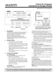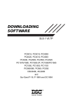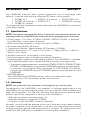
1
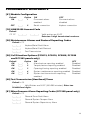
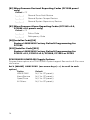
INTRODUCTION
Section 1
The LINKS2450 transmits alarm system information over a long-range radio
network. It may be used with the following DSC alarm control panels:
• PC1580 v1.0
• PC5010 v1.0 and up • PC4010/4020 v3.x
• PC1565 v2.x and up • PC5015 v2.2
• PC5008 v2.x and up
• PC585 v2.x and up
This manual will describe how to install and program the LINKS2450 for connection
to the above panels.
1.1 Specifications
NOTE: If the panel uses automatic SIA or Contact ID communications formats, the
reporting codes the LINKS2450 will send must still be programmed on the panel.
• Power supply: 11.5-14VDC at 750mA (PS1520, PC5204, PC4204, or powered
from Bell+/Aux- control panel terminals)
• Radio transmitter frequency: range from 440 to 470MHz
• Communication Buffer: 80 Events
• Transmission Range: Approximately 16 Kilometers (10 Miles)
• Cabinet dimensions: 4.17” high × 5.75” wide × 1” deep (104mm × 146mm ×
26mm); color: white
• Module supervision via the alarm control panel
• Protected against static and lightning induced transients
• Programming by keypad or downloading software. The LINKS2450 is complete
with a default program and is operational with a minimum of programming.
• To program via a keypad when connected to PC5015, PC5010, PC5008, PC1580,
PC1565 or PC585 panels, program the LINKS2450 using any system keypad
• To program via a keypad when connected to PC4010/4020 v3.0 panels,
program the LINKS2450 using a PC2550RK keypad connected directly to the
LINKS2450.
• EEPROM Memory
The LINKS2450 uses EEPROM memory, which will retain all program
information even if AC and battery power, are removed.
1.2 Antenna
NOTE: You must match the antennas to the frequency you will be using.
The antenna for the LINKS2450 is not supplied. For optimum performance of the
LINKS2450, use a quality antenna system, such as model SLA-532, available from
Safe Link Corporation. This 5/8 over 5/8 wave high performance antenna offers
features specifically designed for security radio installations.
• 5db gain two-piece mast with center coil
• Standard frequency range 440-470MHz
• Five feet of coax with BNC connector attached.
Normally, you will install the antenna on the top of the alarm control panel cabinet.
For better reception at the central station, you can mount the antenna in a remote
location using the optional mounting bracket. A compact 13” replacement mast,
model SLA-313 (3dB gain) is available for limited space installations.
1
INSTALLING THE LINKS2450
Section 2
Before installing the LINKS2450, install and test the security system to which it will
be connected, according to the system’s Installation Manual.
2.1 Unpacking the LINKS2450
Check that each of these parts is included in your LINKS2450 package.
•
•
LINKS2450 circuit board
LINKS2450 cabinet
CAUTION: Due to the sensitivity of the RF circuitry, avoid any contact with the coils
and potentiometers on the LINKS2450 circuit board.
2.2 Select a Mounting Location
The area where you mount the LINKS2450 should be:
• dry
• close to the installed alarm control panel cabinet.
• far from sources of interference, including: electrical noise such as
computers, televisions and electric motors in appliances and heating and air
conditioning units; large metal objects like heating ducts and plumbing which
may shield the antenna. If you must mount the LINKS2450 near such items,
you may have to mount the antenna on a remote bracket away from the
LINKS2450.
• close to the power supply. See section 2.3 “Install a Power Supply”.
2.3 Connect a Power Supply
You can use the Bell+ and Aux- terminals from the control panel to power the
LINKS2450. If you will be using a separate power supply, install it near the
LINKS2450. Refer to the power supply’s installation instructions, for more information.
NOTE: The current drawn by the LINKS2450 and the siren(s) connected to the Bell
terminals must not exceed that specified by the rating of the control panel. Refer to
your control panel’s Intallation Manual for more information.
The wiring between the LINKS2450 and the power supply should not be longer than
indicated in the table below:
Wire Gauge (AWG)
Maximum Wire Length (feet / meters)
22
15' / 4.5m
20
25' / 7.5m
18
40' / 12.0m
You can double the maximum wire length if you double the conductors and connect
them in parallel. Mount the LINKS2450 as close to the power supply as possible.
2
2.4 Mount and Wire the LINKS2450
1. Run the panel wiring and the power supply wiring to the LINKS2450
mounting location.
2. Remove the four screws that attach the LINKS2450 circuit board to the
plastic cabinet.
3. Pull all wires through the hole at the back of the cabinet.
4. Mount the cabinet securely to the wall. Use the appropriate wall anchors
when securing the panel to drywall, plaster, concrete, brick or similar
surfaces.
5. Reattach the LINKS2450 into the mounted cabinet using the four mounting
screws.
6. Find the antenna connection in the hole at the top of the cabinet. Secure the
antenna to the LINKS2450 antenna connector.
NOTE: Make sure an antenna is always connected to the LINKS2450 whenever it
is operated. The unit will not work and may be damaged if an antenna is not installed.
7. Complete all wiring: If you will be connecting the LINKS2450 to a PC5015,
PC5010, PC5008, PC1580, PC1565 or PC585 panel, go to step 7a. If you will
be connecting the LINKS2450 to a PC4010 or PC4020 panel, go to step 7b.
7a. Connect the LINKS2450 according to diagram 2-1. Make sure jumper
J3 on the LINKS2450 is NOT shorted.
7b. Connect the LINKS2450 to a PC2550RK keypad according to diagram
3-1. Make sure jumper J3 on the LINKS2450 IS SHORTED. When you
have finished programming, disconnect the power supply and the
PC2550RK keypad from the LINKS2450. Remove the short from jumper
J3. Connect the LINKS2450 to the control panel according to diagram
2-2.
NOTE: Double-check all wiring to ensure that it is correct. Incorrect wiring
connections may cause the LINKS2450 to operate improperly, or may damage
the unit.
8. Connect the power: Connect the power terminals (VTX+ and VTX–) to a 11.5 14VDC, 1A power supply.
CAUTION: Do not connect the power supply until all other wiring, including the
antenna connection, has been completed and checked to ensure that it is
correct.
3
DIAGRAM 2-1
Hook-up For PC5010, PC5015, PC5008, PC1565,
PC1580, PC585 Panels
NOTE: Programming section [01], option 2 must be OFF for LINKS2450 to work
with these panels.
CAUTION: Due to the sensitivity of the RF circuitry, avoid any contact with the coils
and potentiometers on the LINKS2450 circuit board.
*If power supply supervision is required for the LINKS2450 VTX terminals, use the
PC5204. If no supervision is needed, you can use the PS1520 or the control panel
Bell+/Aux- terminals.
4
DIAGRAM 2-2
Hook-up for PC4010/4020 v3.0 Panels
NOTE: Programming section [01], option 2 must be ON for LINKS2450 to work with
these panels.
CAUTION: Due to the sensitivity of the RF circuitry, avoid any contact with the coils
and potentiometers on the LINKS2450 circuit board.
*If power supply supervision is required for the LINKS2450 VTX terminals, use the
PC4204. If no supervision is needed, you can use the PS1520 or the control panel
Bell+/Aux- terminals .
5
PROGRAMMING THE LINKS2450
Section 3
See section 3.1 for programming instructions when connecting the LINKS2450 to
a PC5015, PC5010, PC5008, PC1580, PC1565 or PC585 panel. See section 3.2 for
programming instructions when connecting the LINKS2450 to a PC4010 or PC4020
v3.0 panel.
3.1 Programming a LINKS2450 Connected to a PC5015, PC5010,
PC5008, PC1580, PC1565 or PC585 Panel
Program the LINKS2450 through Installer’s Programming at a system keypad. For
instructions on using Installer’s Programming sections, please refer to Section 4
“How to Program” in your control panel Installation Manual.
1. Go to Installer’s Programming by entering [*][8][Installer’s code].
2. For PC5015, PC5010, PC5008, PC1565 and PC585: Go to the LINKS2450
programming section by entering [803]. Program the following sections only
(see section 4 for a description of each section). Record your programming
choices in the worksheets at the end of this manual.
[01] Module Configuration
Option 1: Communications Enabled / Disabled
Option 2: Serial Connection / Keybus Connection
[10] LINKS2450 Account Code
[20] Maintenance Alarms and Restoral Reporting Codes
[30] Call Direction Options
[40] Test Transmission (Heartbeat) Timer
[83] Miscellaneous Alarm Reporting Codes (PC1565, PC5008 v2.0
panels only)
3. For PC1580: Go to the LINKS2450 programming section by entering [86].
Program the following sections only. See section 4 for a description of each
section. Record your programming choices in the worksheets at the end of
this manual.
[01] Module Configuration
Option 1: Communications Enabled / Disabled
Option 2: Serial Connection / Keybus Connection
[10] LINKS2450 Account Code
[20] Maintenance Alarms and Restoral Reporting Codes
[30] Call Direction Options
[40] Test Transmission (Heartbeat) Timer
[81] Miscellaneous Alarm Reporting Codes (PC1580 panel only)
[82] Miscellaneous Restoral Reporting Codes (PC1580 panel only)
4.
6
To exit Installer’s Programming, press [#].
3.2 Programming a LINKS2450 for Use with a PC4010/PC4020
v3.0 or higher panel.
There are two stages in programming the LINKS2450 for a PC4010 or PC4020
panel:
1. Program the LINKS2450 programming sections from a PC2550RK keypad
connected directly to the LINKS2450.
2. Program the LINKS2450 toggle options on the PC4010/4020 control panel.
Program the LINKS2450 from a PC2550RK Keypad:
1. Make sure the LINKS2450 is connected to a PC2550RK keypad (refer to
diagram 3-1). Make sure that jumper J3 is shorted.
2. Program the following sections only. Other programming sections are not
relevant to PC4010/4020 panels. See section 4 for a detailed description of
these sections.
Enter the two-digit number for each section you want to program, then, enter
the data required to complete the section programming. If you enter
information into a section and make a mistake, press [#] to exit the section.
Select the section again, and re-enter the information correctly.
Record your programming choices in the worksheets at the end of this
manual.
[01] Module Configuration
Option 1: Communications Enabled / Disabled. Press [1] to alternately
enable or disable the option.
Option 2: Serial Connection (Enabled) / Keybus Connection (Disabled). Press [2] to alternately enable or disable the option.
[10] LINKS2450 Account Code. Enter 2 two-digit hexadecimal numbers.
Refer to your Installation manual for information on Hexadecimal
programming.
[20] Maintenance Alarms and Restoral Reporting Codes. Enter two hexadecimal digits for each code.
[40] Test Transmission (Heartbeat) Timer. Enter two hexadecimal digits.
3. When you have finished programming the above sections, disconnect the
power and the PC2550RK keypad.
4. Connect the LINKS2450 to the panel as in diagram 2-2.
Diagram 3-1
Connecting the LINKS2450 to a
PC2550RK Keypad
7
Program the LINKS2450 Toggle Options on the Panel
At a PC4010 or PC4020 system keypad, enter reference # [000405] and [*], or scroll
to the “LINKS2XXX” programming section. (See the “How to Program” section in
your PC4010/4020 Installation Manual for more information.) Use the arrow keys (<
>) to scroll to each of the following toggle options. Press [*] to toggle the option ON
or OFF. Record your programming choices in the worksheets at the end of this
manual.
LINKS 2XXX
Yes
When enabled the PC4010 or PC4020 will send the events
that are programmed to the LINKS 2450. The PC4010/
4020 will only send the events that have reporting codes
programmed and dialer directions enabled for them.
No
The PC4020 will not send events to the LINKS2450.
Default condition is No.
NOTE: The Communications Toggle option “Comms Enabled” must also be set to
Yes for the PC4010/4020 to be able to send events to the LINKS 2XXX.
To disable the PC4010/4020 telephone communications, but still allow the PC4010/
4020 to communicate events through the LINKS 2XXX, set “Comms Enabled” to
Yes, and the Dialer Directions to No for all 3 telephone numbers. Leaving all 3
telephone numbers unprogrammed will also disable telephone communications.
See the “Communications Programming” section in your PC4010/4020 Installation
Manual for more information.
Alarm/Restore Yes
Alarm and Restoral reporting codes are sent to the central
station by the LINKS2450.
No
Alarm and Restoral reporting codes are not sent to the
LINKS2450.
Yes
Opening and Closing reporting codes are sent to the
central station by the LINKS2450.
No
Opening and Closing reporting codes are not sent to the
LINKS2450
Yes
All other reporting codes are sent to the central station by
the LINKS2450.
No
All other reporting codes are not sent to the LINKS2450
Default: No (Yes on PC4010CF/4020CF panels)
Open/Close
Default: No (Yes on PC4010CF/4020CF panels)
All others
Default: No (Yes on PC4010CF/4020CF panels)
To exit the LINKS2XXX programming section, press [#].
Program Panel Supervision for the LINKS2450
Panel supervision of the LINKS2450 is recommended when connected to PC4010/
4020 panels. To have the panel supervise the LINKS2450, make sure the zone that
the LINKS2450 is connected to on the panel is programmed for LINKS Supervisory
(zone type [28]). When the zone is programmed this way, if the YEL terminal is not
grounded (e.g. the wire is cut), the panel will generate a zone trouble and a LINKS
trouble and will send the reporting code for the zone.
See your PC4010/4020 Installation Manual for information on zone programming.
8
PROGRAMMING DESCRIPTIONS
SECTION 4
[01] Module Configuration
Option 1: Communications Enabled / Disabled
Enable this option to have the LINKS2450 initiate communications for all events that
have reporting codes and call direction options (section [30]) programmed.
Disable this option to test the system.
Option 2: Serial Connection / Keybus Connection
Enable this option if you will use the LINKS2450 with a PC4010/4020 panel. Disable
this option if you will use the LINKS2450 with a PC5015, PC5010, PC5008, PC1580,
PC1565 or PC585 panel.
[10] LINKS2450 Account Code
This 4-digit code is used to identify the system and is transmitted when the
LINKS2450 initiates communications. Program a 4-digit code in this section using
2 two-digit Hexadecimal numbers. Refer to your control panel Installation Manual
for instructions on programming hexadecimal digits.
NOTE: An account number must be entered in this section before the LINKS2450
can send any communications. Programming [FFFF] will disable the LINKS2450.
[20] Maintenance Alarms and Restoral Reporting Codes
Program 2 digit reporting codes for the following:
• Keybus/Serial Fault Alarm: This code will be sent when connection is lost to
the panel for more than 30seconds.
• Keybus/Serial Fault Restoral: This code will be sent when connection is
restored to the panel for more than 30seconds.
• Test Transmission: This code will be sent according to the programming of
section [40], the test transmission timer.
[30] Call Direction Options (PC5015, PC5010, PC5008, PC1580,
PC1565 and PC585 panels only)
Program which of the following reporting code types the LINKS2450 will send to the
central station:
• Alarm/restore reporting
• Tamper/restore reporting
• Opening/closing reporting
• System maintenance reporting
• System test transmission reporting
In most installations, you should program the tranmission of alarm/restore reporting codes
only. Your radio network has limited bandwidth and capacity. The more signals each
LINKS2450 transmits, the fewer LINKS2450s you will be able to install on your network.
[40] Test Transmission (Heartbeat) Timer
Use this feature with appropriately equipped Safe Link radio networks to provide
a higher level of security to a limited number of radios. The LINKS2450 will send test
signals at the interval programmed in this section. If the network does not receive
a test signal, an exception signal is generated and sent to your central station.
9
Special procedures are necessary to activate this feature for a radio account.
Check with Safe Link for more information.
Program the amount of time in minutes (000-255) between LINKS2450 test
transmissions. Program this section as a two-digit hexadecimal number. Refer to
your control panel Installation Manual for instructions on programming hexadecimal digits. If you program [00], the LINKS2450 will not send a test transmission.
In most installations, you should limit the number of LINKS2450s which send test
signals and the number of test signals each LINKS2450 sends. Your radio network
has limited bandwidth and capacity. The more signals each LINKS2450 transmits, the
fewer LINKS2450s you will be able to install on your network.
[81] Miscellaneous Alarm Reporting Codes (PC1580 panel only)
Program 2 digit reporting codes for the following:
• General Zone Fault Alarm: This code will be sent when the LINKS2450
receives a General Zone Fault Alarm event from the PC1580.
• General System Tamper Alarm: This code will be sent when the LINKS2450
receives a General System Tamper Alarm event from the PC1580.
• General System Supervisory Alarm: This code will be sent when the
LINKS2450 receives a General System Supervisory Alarm event from the
PC1580.
[82] Miscellaneous Restoral Reporting Codes (PC1580 panel only)
Program 2 digit reporting codes for the following (see your PC1580 Installation
Manual for more information):
• General Zone Fault Restoral: This code will be sent when the LINKS2450
receives a General Zone Fault Restoral event from the PC1580.
• General System Tamper Restoral: This code will be sent when the
LINKS2450 receives a General System Tamper Restoral event from the
PC1580.
• General System Supervisory Restoral: This code will be sent when the
LINKS2450 receives a General System Supervisory Restoral event from the
PC1580.
NOTE: Sections [81] and [82] apply to the PC1580 only. All other panels will use
the reporting codes that are programmed for these events in the panel.
[83] Miscellaneous Alarm Reporting Codes (PC1565 v2.0,
PC5008 v2.0 panels only)
Program 2 digit reporting codes for the following (see your PC1565 Installation
Manual for more information):
• Police Code: This code will be sent when the LINKS2450 receives a Police
Code event from the PC1565 v2.0 or PC5008 v2.0.
• Delinquency Code: This code will be sent when the LINKS2450 receives a
Delinquency event from the PC1565 v2.0 or PC5008 v2.0.
10
TESTING THE LINKS2450
Section 5
Before testing the LINKS2450, ensure that the control panel is correctly programmed and operating properly. Refer to your system Installation Manual for
instructions on testing your system. The control panel must be programmed
properly in order for the LINKS2450 to operate.
To check that the LINKS2450 is working, apply power to the unit after all wiring
connections have been made. When the LINKS2450 is sending a transmission, the
LED on the circuit board will turn on.
5.1 Performing a LINKS Test Transmission
Contact the monitoring station to request a transmission test. Remove the telephone cord from the RJ31-X jack. Perform a Bell Test as described in the control
panel’s Installation Manual. When the test is complete, contact the monitoring
station to confirm the transmission. Perform additional test transmissions as
required by the central station.
5.2 “On Air” Indication
Whenever the LINKS unit is communicating, the LED on the unit’s circuit board will
turn ON for each round of communications. Each event has 3 rounds. Therefore, if
one reporting code is sent, the LED will activate 3 times to indicate each round.
5.3 Troubleshooting
If the LINKS2450 is not working properly, check that all wiring and all programming
is correct before calling for technical support.
5.4 Testing Tools
The following tools are available from Safe Link:
UHF RF Power Meter - Connects to the antenna jack on the LINKS2450. Indicates
the transmit power of the radio.
UHF Scanner - Checks that the radio is transmitting data.
Frequency Counter - Checks that the LINKS2450 is transmitting on the correct
frequency.
11
RESET LINKS2450 PROGRAMMING TO FACTORY
DEFAULT
Section 6
If you need to reset the LINKS2450 to factory default programming, follow the
directions in the appropriate sections below.
6.1 Reset the LINKS2450 on a PC1580 Panel
To reset the LINKS2450 on a PC1580 panel, enter [96] [Installer’s Code] [96].
6.2 Reset the LINKS2450 on a PC5015 v2.2, PC5010 v2.0,
PC5008, PC1565 or PC585 Panel
To reset the LINKS2450 on a PC5015 v2.2, PC5010 v2.0, PC5008 or PC1565 panel,
enter [993] [Installer’s Code] [993].
NOTE: This command is unavailable on PC5010 v1.0. If v1.0 is used, you must
perform a hardware reset (see section 6.3 below).
6.3 Perform a Hardware Reset (All panels)
To reset the LINKS2450 when connected to a PC5010 v1.0 or a PC4010/4020
panel, you must perform a hardware reset. To do this:
1.
2.
3.
4.
5.
6.
7.
Remove all power from the LINKS2450
Short jumper J3
Remove all wires from the YEL and GRN terminals
With a piece of wire, short the YEL terminal to the GRN terminal
Apply power to the LINKS2450 for 5 seconds.
Remove power from the LINKS2450
Reconnect all original wiring and re-power the LINKS2450
NOTE: If the LINKS2450 is connected to a PC4010/4020 panel, the programming
done in the panel software will not be reset. See section 3.2, step 5 for information
on re-programming the PC4010/4020 sections.
12
PROGRAMMING WORKSHEETS
[01] Module Configuration
Default
ON
I_______I
Option
1
ON
Communications
enabled
OFF
Communications
disabled
OFF
I_______I
2
Serial connection
Keybus connection
[10] LINKS2450 Account Code
Default
FF FF
I_______I_______I
l_______I_______I
Valid entries are 00-FF
Enter two 2-digit hexadecimal numbers.
[20] Maintenance Alarms and Restoral Reporting Codes
Default = FF
I_______I_______I
Keybus/Serial Fault Alarm
I_______I_______I
Keybus/Serial Fault Restoral
I_______I_______I
Test Transmission
[30] Call Direction Options (PC5015, PC5010, PC5008, PC1580
and PC1565 panels only)
Default
ON
ON
ON
ON
ON
I_______I
I_______I
I_______I
I_______I
I_______I
Option
1
2
3
4
5
ON
Alarm/restore reporting enabled
Tamper/restore reporting enabled
Opening/closing reporting enabled
System maintenance reporting enabled
System test transmission reporting
enabled
OFF
Disabled
Disabled
Disabled
Disabled
Disabled
[40] Test Transmission [Heartbeat] Timer
Default = 00
I_______I_______I
Valid Entries are 00-FF (000-255 minutes). Enter two
hexadecimal digits.
[81] Miscellaneous Alarm Reporting Codes (PC1580 panel only)
Default = FF
I_______I_______I
General Zone Fault Alarm
I_______I_______I
General System Tamper Alarm
I_______I_______I
General System Supervisory Alarm
13
[82] Miscellaneous Restoral Reporting Codes (PC1580 panel
only)
Default = FF
I_______I_______I
General Zone Fault Restore
I_______I_______I
General System Tamper Restore
I_______I_______I
General System Supervisory Restore
[83] Miscellaneous Alarm Reporting Codes (PC1565 v2.0,
PC5008 v2.0 panels only)
Default = FF
I_______I_______I
Police Code
I_______I_______I
Delinquency Code
[96][Installer Code][96]
Restore LINKS2450 Factory Default Programming for
PC1580
[993][Installer Code][993]
Restore LINKS2450 Factory Default Programming for
PC5015 v2.2, PC5010 v2.0, PC5008, PC1565 or PC585
PC4010/4020 LINKS2450 Toggle Options
Program these options at a PC4010/4020 system keypad. See section 3.2 for more
information.
Ref # [000405] LINKS 2XXX (use arrow keys (< >) to scroll to each
option)
Option
Default
LINKS 2XXX
N (Y for CF panels)
Alarm/Restore
N (Y for CF panels)
Open/Close
N (Y for CF panels)
All Others
N (Y for CF panels)
14
LIMITED WARRANTY
Safe Link Ltd. warrants that for a period of twelve months from the date of purchase, the
product shall be free from defects in materials and workmanship under normal use and that
in fulfilment of any breech of such warranty, Safe Link Ltd. shall, at its option, repair or replace
the defective equipment upon return of the equipment to its repair depot. This warranty
applies only to defects in parts and workmanship and not to damage incurred in shipping or
handling, or damage due to causes beyond the control of Safe Link Ltd., such as lightning,
excessive voltage, mechanical shock, water damage, or damage arising out of abuse,
alteration or improper application of the equipment.
The foregoing warranty shall apply only to the original buyer, and is and shall be in lieu of any
and all other warranties, whether expressed or implied and of all other obligations or liabilities
on the part of Safe Link Ltd. Safe Link Ltd. neither assumes, nor authorizes any other person
purporting to act on its behalf to modify or to change this warranty, nor to assume for it any
other warranty or liability concerning this product.
In no event shall Safe Link Ltd. be liable for any direct or indirect or consequential
damages, loss of anticipated profits, loss of time or any other losses incurred by the
buyer in connection with the purchase, installation or operation or failure of this
product.
WARNING: Safe Link Ltd. recommends that the entire system be completely tested on a
regular basis. However, despite frequent testing, and due to but not limited to, criminal
tampering or electrical disruption, it is possible for this product to fail to perform as expected.
© 1998 Safe Link Corporation
3825 Lake Austin Blvd., Austin, TX 78703, USA
Telephone:(512)477-7737 Fax:(512)477-7738
29002322 R2
• W A R N I N G •
Please refer to the System Installation Manual for information on
limitations regarding product use and function and information on
the limitations as to liability of the manufacturer.
Long Range RF Transmitter
INSTALLATION MANUAL
Version 1.0
FCC COMPLIANCE STATEMENT
CAUTION: Changes or modifications not expressly approved by Digital Security Controls Ltd.
could void your authority to use this equipment.
This equipment generates and uses radio frequency energy and if not installed and used properly, in
strict accordance with the manufacturer’s instructions, may cause interference to radio and television
reception. It has been type tested and found to comply with the limits for Class B device in accordance
with the specifications in Subpart “B” of Part 15 of FCC Rules, which are designed to provide
reasonable protection against such interference in any residential installation. However, there is no
guarantee that interference will not occur in a particular installation. If this equipment does cause
interference to television or radio reception, which can be determined by turning the equipment off and
on, the user is encouraged to try to correct the interference by one or more of the following measures:
• Re-orient the receiving antenna
• Relocate the alarm control with respect to the receiver
• Move the alarm control away from the receiver
• Connect the alarm control into a different outlet so that alarm control and receiver are on different
circuits.
If necessary, the user should consult the dealer or an experienced radio/television technician for
additional suggestions. The user may find the following booklet prepared by the FCC helpful: “How
to Identify and Resolve Radio/Television Interference Problems”. This booklet is available from the
U.S. Government Printing Office, Washington, D.C. 20402, Stock # 004-000-00345-4.
Notice to the user:
It is the responsibility of the modem user to ensure that the modem / radio
terminal combination has been aligned by qualified personnel before the
equipment is used. Written proof, with the name of the technician and
address of the service depot, should be available on request for inspection
by representatives / radio inspectors of Industry Canada.
TABLE OF CONTENTS
Section 1: Introduction
1
1.1 Specifications ....................................................................................... 1
1.2 Antenna ................................................................................................. 1
Section 2: Installing the Links2450
2
2.1 Unpacking the LINKS2450 ...................................................................... 2
2.2 Select a Mounting Location ..................................................................... 2
2.3 Connect a Power Supply ......................................................................... 2
2.4 Mount and Wire the LINKS2450 .............................................................. 3
Diagram 2-1: Hook-up For PC5010, PC5015, PC5008,
PC1565, PC1580, PC585 Panels ................................................................... 4
Diagram 2-2: Hook-up for PC4010/4020 v3.0 Panels ................................... 5
Section 3: Programming the LINKS2450
6
3.1 Programming a LINKS2450 Connected to a PC5015, PC5010,
PC5008, PC1580, PC1565 or PC585 Panel ......................................... 6
3.2 Programming a LINKS2450 for Use with a
PC4010/PC4020 v3.0 or higher panel. ................................................. 7
Diagram 3-1: Connecting the LINKS2450 to a PC2550RK Keypad .............. 7
Section 4: Programming Descriptions
9
[01] Module Configuration ........................................................................... 9
[10] LINKS2450 Account Code ................................................................... 9
[20] Maintenance Alarms and Restoral Reporting Codes ........................... 9
[30] Call Direction Options (PC5015, PC5010, PC5008,
PC1580, PC1565 and PC585 panels only) .......................................... 9
[40] Test Transmission (Heartbeat) Timer .................................................... 9
[81] Miscellaneous Alarm Reporting Codes (PC1580 panel only) ............ 10
[82] Miscellaneous Restoral Reporting Codes (PC1580 panel only) ........ 10
[83] Miscellaneous Alarm Reporting Codes (PC1565 v2.0,
PC5008 v2.0 panels only) .................................................................. 10
Section 5: Testing the LINKS2450
11
5.1 Performing a LINKS Test Transmission .............................................. 11
5.2 “On Air” Indication .............................................................................. 11
5.3 Troubleshooting .................................................................................. 11
5.4 Testing Tools ....................................................................................... 11
Section 6: Reset LINKS2450 Programming to Factory Default
12
6.1 Reset the LINKS2450 on a PC1580 Panel ......................................... 12
6.2 Reset the LINKS2450 on a PC5015 v2.2, PC5010 v2.0,
PC5008, PC1565 or PC585 Panel ...................................................... 12
6.3 Perform a Hardware Reset (All panels) .............................................. 12
Programming Worksheets
LIMITED WARRANTY
13
inside back cover
i
NOTES:
ii